57 minute read
Electrical System

SPECIAL TOOLS A number of special tools must be available to the technician when performing service procedures in this section. Refer to the current Special Tools Catalog for the appropriate tool description.
Description p/n
Fluke Model 73 Multimeter 0644-191 Fluke Model 77 Multimeter 0644-559 Timing Light 0644-296 MaxiClips 0744-041 Peak Voltage Reading Adapter 0644-307 Test Plug/Error Code List 0444-216 TPS Analyzer 0644-299
NOTE: Special tools are available from the Arctic
Cat Service Department.
TESTING ELECTRICAL COMPONENTS All of the electrical tests should be made using the Fluke Model 73 Multimeter or Model 77 Multimeter and when testing peak voltage, the Peak Voltage Reading Adapter must be used. If any other type of meter is used, readings may vary due to internal circuitry. When troubleshooting a specific component, always verify first the fuse(s) are good, the bulb(s) are good, the connections are clean and tight, the battery is fully charged, and all appropriate switches are activated.
NOTE: For absolute accuracy, all tests should be
made at room temperature of 68° F.
ELECTRICAL CONNECTIONS The electrical connections should be checked periodically for proper function. In case of an electrical failure, check fuses, connections (for tightness, corrosion, damage), and/or bulbs.
Battery
The battery is located in a compartment in front of the left-rear wheel under the driver seat.
NOTE: To access the battery box, the driver’s seat
must be removed.
After being in service, batteries require regular cleaning and recharging in order to deliver peak performance and maximum service life. The following procedures are recommended for cleaning and maintaining lead-acid batteries. Always read and follow instructions provided with battery chargers and battery products. NOTE: Refer to all warnings and cautions provided
with the battery or battery maintainer/charger.
Loss of battery charge may be caused by ambient temperature, ignition OFF current draw, corroded terminals, self discharge, frequent start/stops, and short engine run times. Frequent winch usage, snowplowing, extended low RPM operation, short trips, and high amperage accessory usage are also reasons for battery discharge. Maintenance Charging NOTE: Arctic Cat recommends the use of the CTEK
Multi US 800 or the CTEK Multi US 3300 for battery maintenance charging. Maintenance charging is required on all batteries not used for more than two weeks or as required by battery drain.
1.When charging a battery in the vehicle, be sure the ignition switch is in the OFF position. NOTE: Be sure to maintain the fluid of the battery at
the UPPER LEVEL. Use only distilled water when adding fluid to these batteries.
2.Clean the battery terminals with a solution of baking soda and water.
3.Be sure the charger and battery are in a well-ventilated area and ensure the battery charger cables will not contact any battery acid. Be sure the charger is unplugged from the 110-volt electrical outlet. 4.Connect the red terminal lead from the charger to the positive terminal of the battery; then connect the black terminal lead of the charger to the negative terminal of the battery. NOTE: Optional battery charging adapters are avail-
able from your authorized Arctic Cat dealer to connect directly to your vehicle from the recommended chargers to simplify the maintenance charging process. Check with your authorized Arctic Cat dealer for proper installation of these charging adapter connectors.
5.Plug the battery charger into a 110-volt electrical outlet.
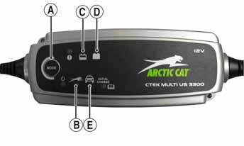
6.If using the CTEK Multi US 800, there are no further buttons to push. If using the CTEK Multi US 3300, press the Mode button (A) at the left of the charger until the Maintenance Charge Icon (B) at the bottom illuminates. The Normal Charge Indicator (C) should illuminate on the upper portion of the battery charger.
NOTE: The maintainer/charger will charge the bat-
tery to 95% capacity at which time the Maintenance Charge Indicator (D) will illuminate and the maintainer/charger will change to pulse/float maintenance. If the battery falls below 12.9 DC volts, the charger will automatically start again at the first step of the charge sequence.
3300A
NOTE: Not using a battery charger with the proper
float maintenance will damage the battery if connected over extended periods.
Charging
NOTE: Arctic Cat recommends the use of the CTEK
Multi US 800 or the CTEK Multi US 3300 for battery maintenance charging.
1.Be sure the battery and terminals have been cleaned with a baking soda and water solution. 2.Be sure the charger and battery are in a well-ventilated area and ensure the battery charger cables will not contact any battery acid. Be sure the charger is unplugged from the 110-volt electrical outlet. 3.Connect the red terminal lead from the charger to the positive terminal of the battery; then connect the black terminal lead of the charger to the negative terminal of the battery. 4.Plug the charger into a 110-volt electrical outlet. 5.By pushing the Mode button (A) on the left side of the charger, select the Normal Charge Icon (E). The
Normal Charge Indicator (C) should illuminate on the upper left portion of the charger. 6.The battery will charge to 95% of its capacity at which time the Maintenance Charge Indicator (D) will illuminate.
NOTE: For optimal charge and performance, leave
the charger connected to the battery for a minimum 1 hour after the Maintenance Charge Indicator (D) illuminates. If the battery becomes hot to the touch, stop charging. Resume after it has cooled.
7.Once the battery has reached full charge, unplug the charger from the 110-volt electrical outlet.
NOTE: If, after charging, the battery does not perform
to operator expectations, bring the battery to an authorized Arctic Cat dealer for further troubleshooting.
RPM Limiter
NOTE: The ROV is equipped with an ECM that
retards ignition timing when maximum RPM is approached. When the RPM limiter is activated, it could be misinterpreted as a high-speed misfire.
Switches
Each time the vehicle is used, switches should be checked for proper operation. Use the following list for reference.
A.Ignition/start switch — engine will run; starter will engage. B.Drive select switch — differential will engage (4WD)/disengage (2WD). C.Reverse/neutral/high/low switch — R/N/H/L will be indicated on the LCD.
D.Headlight switch — high beam, low beam, and lights off can be selected. E.Brake switch — brakelight illuminates and starter can be engaged with vehicle in gear.
Accessory Receptacle/Connector
NOTE: This test procedure is for either the recepta-
cles or the connectors.
VOLTAGE 1.Turn the ignition switch to the ON position; then set the meter selector to the DC Voltage position. 2.Connect the red tester lead to the red/white wire or the positive connector; then connect the black tester lead to ground. 3.The meter must show battery voltage. NOTE: If the meter shows no battery voltage, trou-
bleshoot the battery, fuse, receptacle, connector, or the main wiring harness.
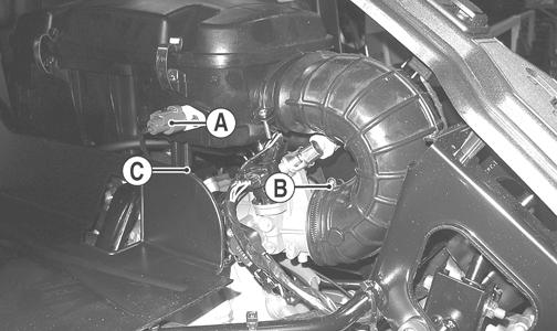
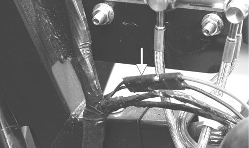
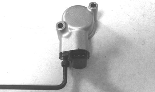
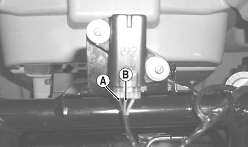
Brakelight Switch
The switch connector is the two-prong black connector below the master cylinder. NOTE: The ignition switch must be in the ON posi-
tion.
VOLTAGE (Wiring Harness Connector) 1.Set the meter selector to the DC Voltage position. 2.Connect the red tester lead to the orange wire; then connect the black tester lead to ground.
PR276A
3.The meter must show battery voltage. NOTE: If the meter shows no battery voltage, trou-
bleshoot the battery, fuse, switch, or the main wiring harness.
NOTE: If the meter shows battery voltage, the main
wiring harness is good; proceed to test the switch/component, the connector, and the switch wiring harness for resistance.
RESISTANCE (Switch Connector) CAUTION
Always disconnect the battery when performing resistance tests to avoid damaging the multimeter.
NOTE: The brake pedal must be depressed for this
test.
1.Set the meter selector to the OHMS position. 2.Connect the red tester lead to one black wire; then connect the black tester lead to the other black wire.
AR621D
3.When the lever is depressed, the meter must show less than 1 ohm.
NOTE: If the meter shows more than 1 ohm of resis-
tance, replace the switch.
Engine Coolant Temperature (ECT) Sensor
1.Connect the meter leads (selector in OHMS position) to the sensor terminals.
2.Suspend the sensor and a thermometer in a container of cooking oil; then heat the oil. NOTE: Neither the sensor nor the thermometer
should be allowed to touch the bottom of the container or inaccurate readings will occur. Use wire holders to suspend the sensor and thermometer.
! WARNING
Wear insulated gloves and safety glasses. Heated oil can cause severe burns.
3.On the ECT sensor when the temperature reaches 40° C (104° F), the meter should read approximately 1136 ohms.
4.On the ECT sensor when the temperature reaches 100° C (212° F), the meter should read approximately 155 ohms. 5.If the readings are not as indicated, the sensor must be replaced. 6.Install the sensor and tighten securely. 7.Connect the leads.
Fan Motor
RESISTANCE (Fan Motor Connector) 1.Set the meter selector to the OHMS position.
PR183A
3.The meter must show less than 1 ohm.
NOTE: If the meter shows more than 1 ohm of resis-
tance, troubleshoot or replace the fan motor.
NOTE: To determine if the fan motor is good, con-
nect the red wire from the fan connector to a 12 volt battery; then connect the black wire from the fan connector to ground. The fan should operate.
! WARNING
Care should be taken to keep clear of the fan blades.
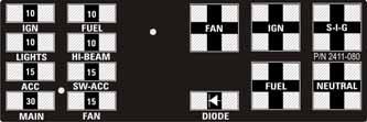
Power Distribution Module (PDM)
FUSES The fuses are located in a power distribution module under the operator’s seat. If there is any type of electrical system failure, always check the fuses first. 1.Remove a fuse from the power distribution module. NOTE: To remove the fuse, compress the locking
tabs on either side of the fuse case and lift out.
2.Set the meter selector to the DC Voltage position. 3.Connect the black tester lead to ground. 4.Using the red tester lead, contact each end of the fuse holder connector terminals individually. 5.The meter must show battery voltage from one side of the connector terminal ends.
NOTE: Battery voltage will be indicated from only
one side of the fuse holder connector terminal; the other side will show no voltage.
NOTE: When testing the HI fuse holder, the head-
light OFF/HI/LO switch must be in the HI position; when testing the LIGHTS fuse holder, the headlight dimmer switch can be in either the HI or LO position.
NOTE: If the meter shows no battery voltage, trou-
bleshoot the battery, switches, power distribution module, or the main wiring harness.
XT
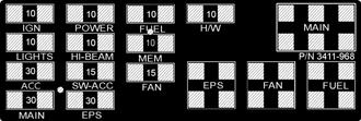
XTX
2411-080
XTZ
3411-968
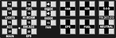
2411-213
CAUTION
Always replace a blown fuse with a fuse of the same type and rating.
1.Set the meter selector to the OHMS position. 2.Connect the red tester lead to one spade end of the fuse; then connect the black tester lead to the other spade end. 3.The meter must show less than 1 ohm resistance. If the meter shows open, replace the fuse. NOTE: Make sure the fuses are returned to their
proper position according to amperage. Refer to the amperage listed under each fuse on the power distribution module.
RELAYS The 4-pin relays are identical plug-in type located on the power distribution module. Relay function can be checked by switching relay positions. The 4-pin relays are interchangeable. NOTE: The module and wiring harness are not a
serviceable component and must be replaced as an assembly.
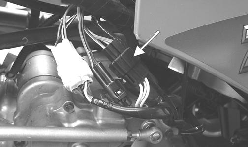
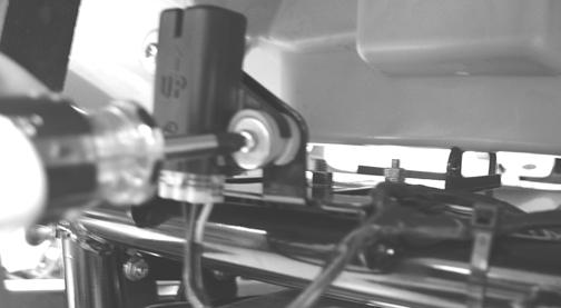
Ignition Coil
The ignition coil is mounted on the fuel pump mounting plate adjacent to the fuel pump. VOLTAGE (Primary Side) See Primary Coil in this sub-section. RESISTANCE
CAUTION
Always disconnect the battery when performing resistance tests to avoid damaging the multimeter.
NOTE: For these tests, the meter selector should be
set to the OHMS position.
Primary Winding 1.Connect the red tester lead to the terminal (with the wire removed); then connect the black tester lead to ground.
PR278A
2.The meter reading must be within specification. Secondary Winding 1.Connect the red tester lead to the high tension lead (with the plug cap removed); then connect the black tester lead to ground. 2.The meter reading must be within specification. NOTE: If the meter does not show as specified,
replace ignition coil.
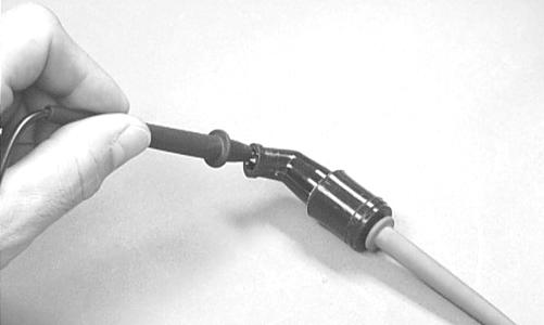
Spark Plug Cap 1.Connect the red tester lead to one end of the cap; then connect the black tester lead to the other end of the cap.
AR603D
2.The meter reading must be within specification. NOTE: If the meter does not show as specified,
replace the spark plug cap.
VOLTAGE Primary Coil 1.Set the meter selector to the DC Voltage position; then disconnect the two wires from the coil.
NOTE: The coil is located to the right of the engine
and may be accessed from behind the right-side seat with the cargo box raised.
2.Connect the red tester lead to the orange wire and the black tester lead to the blue/white wire (H1) or to ground (H2). 3.Turn the ignition switch to the ON position. The meter must show battery voltage.
EFI Sensors/Components
CRANKSHAFT POSITION (CKP) SENSOR To test the CKP sensor, see Stator Coil/Crankshaft Position (CKP) Sensor in this section. OXYGEN (O2) SENSOR
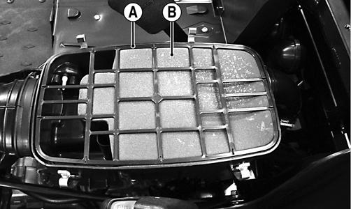
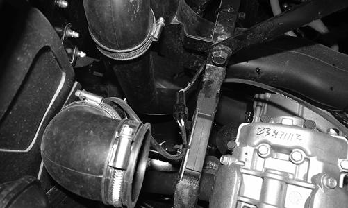
The Oxygen Sensor (O2 Sensor) is located in the exhaust pipe. NOTE: When testing the resistance of the sensor’s heater, the engine/exhaust pipe must be at room temperature (65-75° F) or inaccurate readings will occur.
1.Open the cargo box; then remove the driver’s seat, air filter cover, and air filter. 2.Disconnect the sensor.
PR859
NOTE: For this test, the meter must be in OHMS
position.
3.On the sensor side of connector, connect the black (negative) test lead to one white wire pin; then connect the red (positive) test lead to the other white wire pin. Readings should be between 6.7 and 10.1 ohms.
NOTE: If the meter does not read as specified,
replace the sensor.
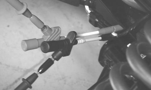
MANIFOLD ABSOLUTE PRESSURE (MAP) SENSOR (550/1000) 1.Disconnect the MAP connector from the pressure sensor located on the throttle body. 2.Select DC Voltage on the tester and turn the ignition switch to the ON position. 3.Connect the black tester lead to the black/green wire and the red tester lead to the orange/blue wire. The meter should read 4.5-5.5 DC volts. If the meter does not read as specified, check the ECM connector or wiring. 4.Connect the MAP to the harness; then using Maxi-
Clips, connect the red tester lead to the brown/white wire and the black tester lead to the black/green wire.
With the engine running at idle speed, the meter should read approximately 1.5 DC volts. NOTE: If the meter does not read as specified,
replace the sensor.
MANIFOLD ABSOLUTE PRESSURE/ INLET AIR TEMPERATURE (MAP/IAT) SENSOR (700)
NOTE: Preliminary checks may be performed on this
component using the diagnostic mode on the LCD gauge (see EFI Diagnostic System (XTX) in this section).
1.Disconnect the MAP/IAT connector from the sensor located on top of the throttle body. 2.Select DC Voltage on the tester and turn the ignition switch to the ON position. 3.Connect the black tester lead to the black/pink wire and the red tester lead to the orange/blue wire. The meter should read 4.5-5.5 DC volts. If the meter does not read as specified, check the ECM connector or wiring. 4.Connect the MAP/IAT to the harness; then using
MaxiClips, connect the red tester lead to the brown/white wire and the black tester lead to the black/pink wire. With the engine running at idle speed, the meter should read approximately 2.5 DC volts (MAP sensor signal). 5.Connect the red tester lead to the green/red wire.
With the engine at idle and at room temperature (approximately 60° F), the meter should read approximately 2.9 DC volts. NOTE: If the meter does not read as specified,
replace the sensor.
Speed Sensor
TESTING
NOTE: Prior to testing the speed sensor, inspect the
three-wire connector on the speed sensor for contamination, broken pins, and/or corrosion.
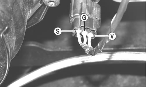
1.Set the meter selector to the DC Voltage position. 2.With appropriate needle adapters on the meter leads, connect the red tester lead to the voltage lead (V); then connect the black tester lead to the ground lead (G).
PR279A
3.Turn the ignition switch to the ON position. 4.The meter must show approximately 6 DC volts. 5.Leave the black tester lead connected; then connect the red tester lead to the signal lead pin (S). 6.Slowly move the vehicle forward or backward; the meter must show 0 and approximately 6 DC volts alternately. NOTE: If the sensor tests are within specifications, the
LCD gauge must be replaced.
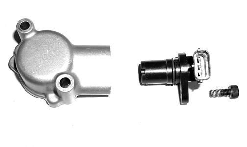
REPLACING (XT/XTX) 1.Disconnect the three-wire connector from the speed sensor harness or from the speed sensor; then remove the
Allen-head cap screw securing the sensor to the sensor housing. 2.Remove the sensor from the sensor housing accounting for an O-ring.
CD070
3.Install the new speed sensor into the housing with new O-ring lightly coated with multi-purpose grease; then secure the sensor with the Allen-head cap screw (threads coated with blue Loctite #242). Tighten securely.
CD071
Electronic Power Steering (EPS) (XTZ)
The electronic power steering (EPS) system is an electro-mechanical device that utilizes 12 volt DC power to drive a motor linked to the steering shaft to assist the driver when rotating the steering wheel. Driver steering inputs are detected by a torque-sensing transducer assembly within the EPS housing. These inputs are converted to electronic signals by the transducer and control circuitry to tell the motor which way to drive the steering shaft. When no steering input (pressure on the steering wheel) is detected, no torque signal is generated, and no steering assist is provided by the motor. The EPS system is battery-system powered; therefore, the battery must be in good condition and fully charged. Power delivery and overload protection are provided by an EPS relay and 30-amp fuse, located under the seat in the Power Distribution Module (PDM). If a system malfunction occurs, a malfunction code “P0635” will be displayed on the LCD gauge. Initially, the gauge will go blank for 30 seconds and the code will flash: then the gauge will return to normal except the code will continue to be displayed. The following is a list of conditions that can generate a malfunction code. All conditions with the exception of item 5 are external to the EPS assembly and therefore can be cleared without replacement of the EPS assembly. Make sure to thoroughly troubleshoot the entire system before replacing the EPS assembly. NOTE: The EPS assembly is not serviceable and no
service parts or parts lists are available. The EPS is only serviceable as an assembly and must not be disassembled or EPS warranty will be voided.
CAUTION
Do not attempt to check resistance of the EPS motor (2-pin input receptacle). There are internal capacitors holding a charge that can cause internal damage to an ohmmeter.
Malfunction code P0635 will appear if one of the following six conditions occur: 1.Battery system power failure:
A.30 amp EPS fuse blown
B.EPS relay failure
C.EPS voltage less than 8.5 DC volts for more than two seconds
2.Ignition switch ON for more than five minutes with the engine not running. 3.Vehicle Speed Signal Malfunction (engine speed must exceed 2700 RPM for more than 60 seconds to generate a malfunction code - timer resets if engine drops below 2700 RPM).
A.Diode defective (open or shorted)
B.Diode not installed
C.Diode installed in reverse
D.Speed sensor defective
E.Speed sensor signal erratic
F.Speed sensor signal present but without engine speed signal
G.Speed sensor power from LCD gauge interrupted
H.Incorrect LCD gauge installed 4.Engine Speed Signal Malfunction (vehicle speed must exceed 5 MPH for more than two seconds - timer resets if speed drops below 5 MPH.
A.No engine speed signal
B.Erratic engine speed signal 5.EPS Control Circuit Malfunction.
The following procedures may be helpful in determining the source of a malfunction code:
Condition: Ignition Key Switch ON and NO EPS assist when moving the handlebar. Code “P0635” flashing.
NOTE: Prior to troubleshooting below, make sure
that Ignition Key Switch has not been left on with the engine not started. After five minutes, this will deactivate the EPS and display the malfunction code. Turn Ignition Key Switch OFF and back to ON to reset and reactivate the EPS. If code and symptom persists, continue as follows:
1.Check 30 amp EPS fuse. 2.Check EPS relay (may be switched with any other 4-pin relay on PDM - replace relay if EPS normal after switching). 3.Disconnect 2-pin connector on the EPS assembly and connect a volt meter set to DC voltage to the harness (black meter lead to BLK and red meter lead to
ORG/BRN).With the ignition switch to the ON position, the meter must read more than 8.5 DC volts (if correct voltage is not present, check connections and wiring harness).
Condition: Ignition switch ON and EPS assist normal when moving handlebar. Code “P0635” flashing. 1.Check for speed sensor signal by disconnecting the 8-pin connector from the EPS assembly and using a multi-meter set to the DC volt position, connect the black lead to the PNK/YEL wire and the red lead to the ORG wire. With the ignition switch turned to the
ON position, slowly move the vehicle forward or backward. The meter must alternate from 0 DC volts to approximately 12 DC volts. If meter readings are not as specified:
A.Check EPS diode for correct installation or open diode (replace diode or install correctly).
B.Check speed sensor using procedure found in this section (replace speed sensor/install proper gauge).
CAUTION
Do not attempt to disassemble the EPS assembly as there are no serviceable components within the assembly and damage will occur voiding the EPS warranty.
2.Check for engine speed signal by disconnecting the 8-pin connector from the EPS assembly and using a multi-meter set to the AC voltage position, connect one lead to any BLK wire and the other lead to
YEL/VLT wire. Start the engine and with the engine idling, the meter should read approximately 7.5 AC volts. If meter reading is not as specified:
A.Check the wiring harness from EPS to gauge (YEL/VLT wire - repair wiring).
B.Check the AC generator (see Stator Coil/Crankshaft Position (CKP) Sensor in this section). If not to specifications, replace the stator coil. If after completing the above checks with normal results and malfunction code “P0635” persists, the EPS assembly must be replaced. To replace the EPS assembly, see the Steering/Frame/Controls section.
Electronic Power Steering (EPS) (XTX)
The EPS system is an electro-mechanical device that utilizes 12 volt DC power to drive a motor linked to the steering shaft to assist the driver when rotating the steering wheel. Driver steering inputs are detected by a torque-sensing transducer assembly within the EPS housing. These inputs are converted to electronic signals by the transducer and control circuitry to tell the motor which way to drive the steering shaft. When no steering input (pressure on the steering wheel) is detected, no torque signal is generated, and no steering assist is provided by the motor. The EPS system is battery-system powered; therefore, the battery must be in good condition and fully charged. Power delivery and overload protection are provided by an EPS relay and 30-amp fuse, located under the seat in the Power Distribution Module (PDM). If a system malfunction occurs, a diagnostic trouble code (DTC) will flash on the LCD gauge until the condition is corrected, the ignition key is cycled, or the EPS recovers. The following is a list of conditions that can generate a code.
Code Fault Description Fault Condition Possible Cause EPS Fault Recovery Method
C1301 Over Current EPS internal over-current condition Internal EPS Condition Correct EPS condition* has been detected C1302 Excessive Current Error EPS internal current measurement Internal EPS Condition Correct EPS condition* error has been detected
C1303 Torque Sensor Range Fault EPS internal torque sensor range condition has been detected Internal EPS Condition Correct EPS condition*
C1304 Torque Sensor Linearity Fault
EPS internal torque sensor linearity condition has been detected C1305 Rotor Position Encoder EPS internal rotor position encoder condition has been detected Internal EPS Condition Correct EPS condition*
Internal EPS Condition Correct EPS condition*
C1306 System Voltage Low EPS battery power low-voltage condition has been detected
C1307 System Voltage High EPS battery power over-voltage condition has been detected System voltage low (less than 11 VDC at the EPS). Wire harness issue, faulty voltage regulator, weak battery or loose battery terminals. EPS will auto-recover when the battery supply returns to normal
System voltage high (more than 16 VDC at the EPS). Wire harness issue, faulty voltage regulator or loose battery terminals. EPS will auto-recover when the battery supply returns to normal
C1308 Temperature Above 110° C EPS internal 110° C over-temp condition has been detected Clean the EPS housing and cooling fins. EPS will auto-recover when internal temperature drops below 105° C
Clean the EPS housing and cooling fins. EPS will auto-recover when internal temperature drops below 115° C
C1310 Vehicle Speed High Vehicle speed signal received by the EPS exceeds the maximum speed specification Intermittent main harness wires, defective speed-sensor, or intermittent speed sensor wires. EPS will auto-recover when the vehicle speed signal drops below the maximum speed specification
C1311 Vehicle Speed Low Vehicle speed signal received by the EPS is zero or missing Broken main harness wires, defective speed-sensor, or broken speed sensor wires. EPS will auto-recover when the vehicle speed signal returns to normal
C1312 Vehicle Speed Faulty Vehicle speed CAN signal received by the EPS incorrect or missing Broken main harness CAN wires, defective speed-sensor, or broken speed sensor wires. EPS will auto-recover when the vehicle speed signal returns to normal
C1313 Engine RPM High Engine RPM signal received by the EPS exceeds the maximum RPM specification C1314 Engine RPM Low Engine RPM signal received by the EPS suddenly dropped below 500 RPM Intermittent main harness RPM wires, intermittent voltage regulator, intermittent ACG stator wires. EPS will auto-recover when engine RPM signal drops below the maximum RPM specification
Handlebar switch in the "OFF" position, broken main harness RPM wires, defect voltage regulator, broken ACG stator wires. EPS will auto-recover when engine RPM signal returns to normal
C1315 Engine RPM Faulty Engine RPM CAN signal received by the EPS incorrect or missing C1316 EEPROM Error EPS internal memory error has been detected Broken main harness CAN wires or defective ECM.
EPS will auto-recover when engine RPM signal returns to normal Internal EPS condition Correct EPS condition*
C1317 CAN Bus Error The EPS has lost CAN communication with the EFI ECM Broken CAN wires in the main harness. EFI ECM connector has been disconnected. Correct EPS condition*
C1318 Internal CRC Error EPS internal CRC calculation condition has been detected
C1319 Boot Counter Exceeded EPS internal application code condition has been detected EPS reflash has failed. Battery power was lost, or the keyswitch was turned off, during EPS reflash programming. EPS must be reprogrammed
Intermittent power has prevented a successful application code launch. Correct EPS power condition*
C1320 Incorrect Vehicle Speed-to-RPM Ratio Vehicle speed signal received by the EPS exceeds 10 MPH, but the engine RPM signal less than 500 RPM Intermittent or broken main harness RPM wires, intermittent voltage regulator, intermittent or broken ACG stator wires. Correct EPS condition*
C1321 Vehicle Speed Erratic Vehicle speed signal received by the EPS changing at an unrealistic rate Intermittent main harness, intermittent speed sensor, dirty speed senor or trigger wheel. Correct EPS vehicle speed signal condition*
C1322 Engine RPM Lost Engine RPM signal received by the EPS exceeds 500 RPM and then is zero or missing Handlebar switch in the "OFF" position, broken main harness RPM wires, defect voltage regulator, broken ACG stator wires. EPS will auto-recover when engine RPM signal returns to normal
C1323 "EPS OFF" Gauge Display Battery power has been applied to the EPS for more than 5-minutes, but no engine RPM signal has been detected The EPS has been automatically disabled, after 5-minutes of inactivity, to conserve battery power. EPS will auto-recover when engine is started or the keyswitch is cycled On-Off-On
C1324 Loss of CAN communication with EPS unit The gauge has lost CAN communication with the EPS Broken CAN wires in the main harness or disconnected EPS. This is not an EPS generated DTC; gauge DTC display only. Gauge DTC display will clear when the EPS-to-gauge CAN communication is restored.
C1325 Dual Loss EPS loss of both the vehicle speed and the engine RPM signals has been detected Handlebar switch in the "OFF" position, the engine stalled (keyswitch "ON"), broken harness wires, loss of CAN data signal. EPS will auto-recover when either the vehicle speed or engine RPM signal is restored.
C1326 Rotor Position Encoder EPS internal rotor position encoder variance condition has been detected Internal EPS Condition Correct EPS condition*
C1327 Voltage Converter Error (Low) EPS internal voltage converter low-voltage condition has been detected Internal EPS Condition Correct EPS condition*
C1328 Voltage Converter Error (High) EPS internal voltage converter over-voltage condition has been detected Internal EPS Condition Correct EPS condition*
C1329 Internal Data Error EPS internal preloaded data condition has been detected Internal EPS Condition EPS must be reprogrammed
* After correcting the condition, cycle the key switch On-Off-On The following test may help in determining the source of a code:
NOTE: The EPS assembly is not serviceable and
must not be disassembled or EPS warranty will be voided. Make sure to thoroughly troubleshoot the entire system before replacing the EPS assembly.
Condition: Ignition Key Switch ON and NO EPS assist when moving the steering wheel. Code flashing.
NOTE: Prior to troubleshooting below, make sure the
Ignition Key Switch has not been left on with the engine not started. After five minutes, this will deactivate the EPS and display the code. Turn the Ignition Key Switch OFF and back to ON to reset and reactivate the EPS. If code and symptom persists, continue as follows:
1.Check 30-amp EPS fuse. 2.Check EPS relay (may be switched with any other 4-pin relay on PDM - replace relay if EPS normal after switching).
3.Disconnect 2-pin connector on the EPS assembly and connect a volt meter set to DC voltage to the harness (black meter lead to BLK and red meter lead to
ORG/BRN).With the ignition switch to the ON position, the meter must read more than 8.5 DC volts (if correct voltage is not present, check connections and wiring harness - if correct voltage is present, replace EPS assembly see Steering/Frame/Controls).
CAUTION
Do not attempt to check resistance of the EPS motor (2-pin input receptacle). There are internal capacitors holding a charge that can cause internal damage to an ohmmeter.
If after completing the above check with normal results and a code persists, the EPS assembly must be replaced (see Steering/Frame/Controls).
Ignition Switch
To access the ignition switch, dash switches, front accessory connectors, and front switched accessory connector, the dash must be unfastened and slid to the rear.
VOLTAGE 1.Set the meter selector to the DC Voltage position. 2.Connect the red meter lead to the red wire; then connect the black meter lead to ground. 3.Meter must show battery voltage. NOTE: If the meter shows no battery voltage, trou-
bleshoot the main 30 amp fuse, the battery, or the main wiring harness.
4.Connect the red meter lead to the red/black wire; then with the black lead grounded, turn the ignition switch to the ON position. The meter must show battery voltage. 5.Connect the red meter lead to the yellow/green wire; then with the black lead grounded, turn the ignition switch to the START position. The starter should engage and the meter must show battery voltage. NOTE: When the starter is engaged, battery voltage
will be approximately 10.5 DC volts.
Headlight Switch
VOLTAGE 1.Connect the red meter lead to the gray wire; then connect the black meter lead to the black wire.
2.Turn the ignition switch to the ON position. The meter must show battery voltage. NOTE: If the meter does not show battery voltage,
troubleshoot the LIGHTS fuse on the power distribution module, the ignition switch, or the main harness.
3.Connect the red meter lead to the yellow wire; then select the high beam position on the headlight switch. The meter must show battery voltage. 4.Connect the red meter lead to either of the two white wires; then select the low beam position on the headlight switch. The meter must show battery voltage. NOTE: The battery voltage will show lower in steps
3 and 4 due to electrical loading of the headlights.
Drive Select Switch
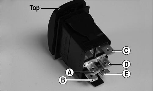
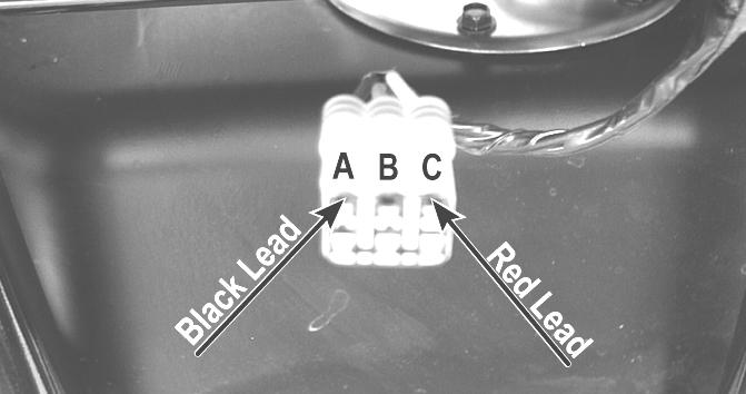
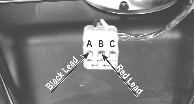
RESISTANCE 1.Remove the switch assembly from the dash; then disconnect the harness from the switch.
NOTE: The switch can be removed from the dash
using a thin, flat pry bar or suitable putty knife. It is not necessary to remove the dash to remove the switch.
2.Using an ohmmeter, the following readings must be observed.
PR566A
2WD 4WD DIFFERENTIAL LOCK
A to D <1 ohm A to D <1 ohm A to D <1 ohm C to E <1 ohm C to E <1 ohm C to E <1 ohm A to B Open A to B <1 ohm A to B <1 ohm A to C Open A to C Open A to C <1 ohm A to E Open A to B <1 ohm A to C <1 ohm
VOLTAGE
NOTE: Voltage tests must be made with the switch
and the actuator connected. The meter can be connected at the actuator connector using a break-out harness or MaxiClips.
1.Connect the black tester lead to the black wire; then turn the ignition switch to the ON position. 2.Select the DC Volts position on the tester and observe the meter readings for each of the three switch positions.
WIRE COLOR 2WD 4WD DIFFERENTIAL LOCK
Black to Orange12.0 DC Volts12.0 DC Volts 12.0 DC Volts
Black to 11.5 DC Volts 0 DC Volts 0 DC Volts
White/Green
Black to 11.5 DC Volts11.5 DC Volts 0 DC Volts
White/Red NOTE: If the meter does not show voltages accord-
ing to the chart, make sure the front drive actuator is plugged in; then troubleshoot the switch, ignition fuses, battery connections, or wiring harness.
Reverse Override Switch
VOLTAGE
NOTE: To perform the following tests, the ignition
switch must be in the ON position and the transmission shifted into reverse gear.
1.Connect the red meter lead to the black/blue wire and the black meter lead to a suitable ground; then select 2WD on the drive select switch. The meter must show approximately 1.5 DC volts. 2.Depress the reverse override switch. The meter showing should not change from step 1. 3.Select 4WD on the drive select switch. The meter must show approximately 5 DC volts. 4.Depress the reverse override switch. The meter must show approximately 1.5 DC volts. 5.Connect the red meter lead to the red/yellow wire. The meter must show approximately 1.5 DC volts. Depress the reverse override switch. The meter must show approximately 1.5 DC volts. 6.Connect the red meter lead to the red/green wire. The meter should show 0 DC volts.
7.Depress the reverse override switch. The meter must show approximately 5 DC volts.
Front Drive Actuator
NOTE: With the engine stopped and the ignition switch
in the ON position, a momentary “whirring” sound must be noticeable each time the drive select switch is moved to 2WD and 4WD. Test the switch, 30 amp fuse, and wiring connections prior to testing the actuator.
NOTE: The differential must be in the unlocked position
for this procedure.
VOLTAGE 1.Locate the 4-wire connector for the front drive selector actuator on the frame to the right of the differential; then connect the red meter lead to the orange wire using a
MaxiClip.
PR293
2. Connect the black lead to the black wire using a Maxi-
Clip; then select 2WD on the drive select switch.
PR295
NOTE: The black tester lead can remain connected
to the black wire for the remaining tests.
3.Turn the ignition switch to the ON position. The meter must show battery voltage. NOTE: If battery voltage is not shown, troubleshoot
the 10 amp ignition (IGN) fuse on the power distribution module, the ignition switch, or the main wiring harness.
4.Connect the red meter lead to the white/red wire. The meter must show battery voltage. 5.Select 4WD on the drive select switch. The meter must show 0 DC volts.
6.Connect the red meter lead to the white/orange wire.
The meter must show battery voltage. 7.Engage the differential lock. The meter must show 0
DC volts.
NOTE: If the meter does not show 0 DC volts, rock
the vehicle to help engage the differential lock; then troubleshoot the drive select switch.
Stator Coil/Crankshaft Position (CKP) Sensor
VOLTAGE (AC Generator - Regulated Output) 1.Set the meter selector to the DC Voltage position. 2.Connect the red tester lead to the positive battery post; then connect the black tester lead to the negative battery post. 3.With the engine running at a constant 5000 RPM (with the headlights on), the meter must show 14-15.5 DC volts.
CAUTION
Do not run the engine at high RPM for more than 10 seconds.
NOTE: If voltage is lower than specified, test AC
Generator - No Load.
VOLTAGE (AC Generator - No Load) The connector is the black three-pin one on the left side above the shift lever.
FI083B
NOTE: Test the connector coming from the engine.
1.Set the meter selector to the AC Voltage position. 2.Test between the three yellow wires (H1) or the three black wires (H2) for a total of three tests. 3.With the engine running at a constant 5000 RPM, all wire tests must be within specification.
CAUTION
Do not run the engine at high RPM for more than 10 seconds.
NOTE: If both stator coil tests failed, check all con-
nections, etc., and test again. If no voltage is present, replace the stator assembly.
RESISTANCE (AC Generator) CAUTION
Always disconnect the battery when performing resistance tests to avoid damaging the multimeter.
1.Set the meter selector to OHMS position. 2.Test between the three yellow wires (H1) or the three black wires (H2) for a total of three tests. 3.The meter reading must be within specification. RESISTANCE (Crankshaft Position Sensor) 1.Set the meter selector to the OHMS position. 2.Connect the red tester lead to the blue wire (XT/XTZ) or brown wire (XTX); then connect the black tester lead to the green wire (XT/XTZ) or white wire (XTX). The meter reading must be within specification. AC VOLTAGE
NOTE: The battery must be at full charge for these
tests.
Crankshaft Position Sensor 1.Set the meter selector to the AC Voltage position. 2.Connect the red tester lead to the blue wire (XT/XTZ) or brown wire (XTX); then connect the black tester lead to the green wire (XT/XTZ) or white wire (XTX). 3.Crank the engine over using the electric starter. 4.The meter reading must be within specification.
Starter Motor
NOTE: The starter motor is not a serviceable component. If the motor is defective, it must be replaced.
REMOVING 1.Disconnect the battery.
CAUTION
Always disconnect the negative battery cable from the battery first; then disconnect the positive cable.
2.Remove the nut securing the positive cable to the starter motor; then remove the cable from the starter. 3.Remove the two cap screws securing the starter motor with ground wires to the crankcase; then remove the starter motor. Account for the wiring forms and an O-ring.
INSTALLING 1.Apply a small amount of grease to the O-ring seal on the starter motor; then install the starter into the crankcase. Secure with two machine screws and wiring forms. 2.Secure the positive cable to the starter motor with the nut.
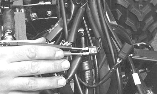
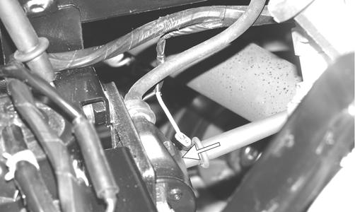
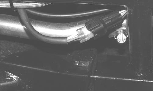
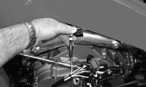
3.Connect the battery. TESTING VOLTAGE Perform this test on the starter motor positive terminal. To access the terminal, slide the boot away. NOTE: The ignition switch must be in the ON posi-
tion, and the shift lever in the NEUTRAL position.
1.Set the meter selector to the DC Voltage position. 2.Connect the red tester lead to the starter terminal; then connect the black tester lead to ground. 3.With the starter button depressed, the meter must show battery voltage and the starter motor should operate.
AR607D
NOTE: If the meter showed battery voltage but the
starter motor did not operate or operated slowly, inspect battery voltage (at the battery), starter motor condition, and/or ground connections.
NOTE: If the meter showed no battery voltage,
inspect the main fuse, ground connections, starter motor lead, battery voltage (at the battery), starter relay, or the neutral start relay.
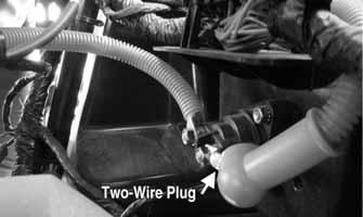
Starter Relay
1.Remove the seats and center console; then using the multimeter set to the DC Voltage position, check the relay as follows. 2.Connect the red tester lead to the positive battery cable connection; then connect the black tester lead to the starter cable connection. The meter must show battery voltage.
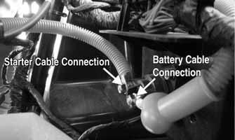
PR841A
NOTE: Make sure the ignition switch is in the ON
position, transmission in neutral, and parking brake set.
3.Depress the starter button while observing the multimeter. The multimeter should drop to 0 volts and a
“click” should be heard from the relay. NOTE: If a “click” is heard and more than one volt is
indicated by the multimeter, replace the starter relay. If no “click” is heard and the multimeter continues to indicate battery voltage, proceed to step 4.
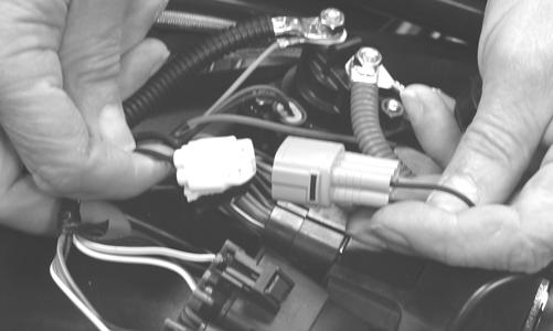
4.Disconnect the two-wire plug from the starter relay; then connect the red tester lead to the green wire and the black tester lead to the black wire.
PR841B
5.Depress the starter button and observe the multimeter.
NOTE: If battery voltage is indicated, replace the
starter relay. If no voltage is indicated, proceed to Neutral Start Relay check.
Electronic Control Unit (ECM)
The ECM is located beneath the seat near the battery. NOTE: The ECM is not a serviceable component. If
the unit is defective, it must be replaced.
The ECM is rarely the cause for electrical problems; however, if the ECM is suspected, substitute another ECM to verify the suspected one is defective. This EFI system has a built-in feature that will only allow an ECM of the same part number to be used in these models. Do not attempt to substitute an ECM from a different model as the system will not allow it to start. Error codes can be cleared by following the procedures located in the ECM Error Codes sub-section in this section.
Regulator/Rectifier
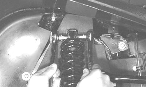
The regulator/rectifier is located under the operator’s seat next to the battery. Try to verify all other charging system components before the regulator/rectifier is replaced. TESTING 1.Start engine and warm up to normal operating temperature; then connect a multimeter (set at the DC
Voltage position) to the battery as follows. 2.Connect the red tester lead to the positive battery post and the black tester lead to the negative battery post. 3.Slowly increase RPM. The voltage should increase with the engine RPM to a maximum of 15.5 DC volts.
NOTE: If voltage rises above 15.5 DC volts, the reg-
ulator is faulty or a battery connection is loose or corroded. Clean and tighten battery connections or replace the regulator/rectifier. If voltage does not rise, see Stator Coil/Crankshaft Position (CKP) Sensor Voltage in this section. If charging coil voltage is normal, replace the regulator/rectifier.
Headlights
The connectors are the four 2-prong ones secured to the headlight bulbs (two on each side). VOLTAGE
NOTE: The low beams are the outside bulbs (black
and white wires) and the high beams are the inside bulbs (yellow and black wires). Always connect the black tester lead to the black wires. The ignition switch must be in the ON position.
1.Set the meter selector to the DC Voltage position. 2.Set the light switch to the correct position for the affected light; then connect the black tester lead to the black wire using a MaxiClip. 3.Connect the red tester lead to the yellow wire (high beam) or white wire (low beam) using a MaxiClip.
The meter must show battery voltage.
NOTE: If battery voltage is not shown in any test,
inspect the LIGHTS fuse on the power distribution module, headlight switch, ignition switch, switch connectors, or wiring harness.
Taillight-Brakelight
VOLTAGE (Taillight)
NOTE: Perform this test at the socket end of the tail-
light-brakelight harness (pigtail). The ignition switch must be in the ON position and either high beam or low beam selected on the light switch.
1.Set the meter selector to the DC Voltage position. 2.Connect the black tester lead to the black wire; then connect the red tester lead to the white wire. The meter should show battery voltage. 3.With the ignition key in the LIGHTS position, the meter must show battery voltage. NOTE: If battery voltage is not shown and the head-
lights are illuminated, inspect the three-wire connector in the left-rear canopy tube at the juncture of the canopy tube and lower frame. If battery voltage is shown on the meter, replace the bulb.
VOLTAGE (Brakelight)
NOTE: Perform this test at the socket end of the tail-
light/brakelight harness (pigtail). The ignition switch must be in the ON position.
1.Set the meter selector to the DC Voltage position. 2.Connect the red tester lead to the red/blue wire; then connect the black tester lead to the black wire.
3.With the brake applied, the meter must show battery voltage. NOTE: If the meter shows no voltage, inspect the 10
amp ignition (IGN) fuse, brakelight switch, wiring harness, or connectors.
Ignition Timing
The ignition timing cannot be adjusted; however, verifying ignition timing can aid in troubleshooting other components. To verify ignition timing, use the following procedure. NOTE: To check ignition timing, the seats and cen-
ter console must be removed.
1.Attach the Timing Light to the spark plug high tension lead; then remove the timing inspection plug from the left-side crankcase cover.
2.Start the engine and using the RPM function on the speedometer/tachometer, run at 1500 RPM; ignition timing should be 10° BTDC. 3.Install the timing inspection plug. If ignition timing cannot be verified, the rotor may be damaged, the key may be sheared, the trigger coil bracket may be bent or damaged, or the ECM may be faulty.
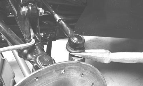
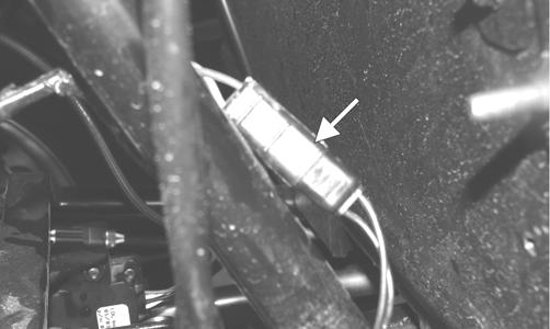
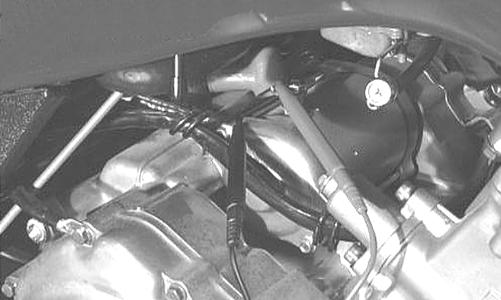
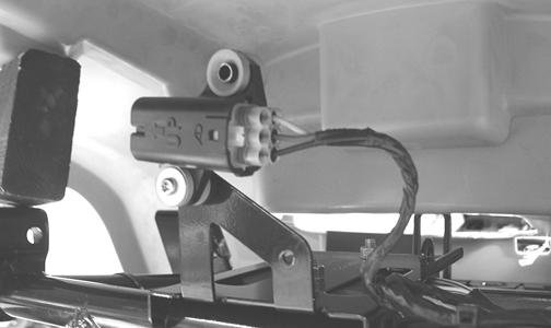
Tilt Sensor
! WARNING
Incorrect installation of the tilt sensor could cause sudden loss of engine power which could result in loss of vehicle control resulting in injury or death.
CAUTION
Do not drop the tilt sensor as shock can damage the internal mechanism.
SUPPLY VOLTAGE 1.Disconnect the three-wire connector from the sensor; then select DC Voltage on the multimeter and connect the red tester lead to the orange wire (C) and the black tester lead to the black wire (A).
CD706A
2.Turn the ignition switch to the ON position. The multimeter should read battery voltage. If battery voltage is not indicated, check the 30-amp fuse, wiring harness, or the ignition switch. 3.Remove the red tester lead and connect to the blue/brown wire (B). The multimeter should read approximately 2.5 DC volts. If the specified voltage is not indicated, check wire connections at the ECM or substitute another ECM to verify the test.
CD706B
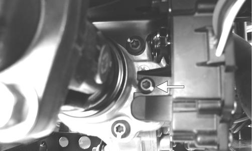
OUTPUT VOLTAGE
NOTE: Needle adapters will be required on the mul-
timeter leads as the following tests are made with the sensor connected.
1.Connect the three-wire plug to the sensor; then remove the right-side mounting screw securing the sensor to the rear frame.
CD707
2.Install the needle adapters to the multimeter leads; then select DC Voltage on the multimeter. 3.Connect the red tester lead to the blue/brown wire (B) and the black tester lead to the black/yellow wire (A); then turn the ignition switch ON and observe the meter. The meter should read 0.8-3.0 DC volts.
CD705B
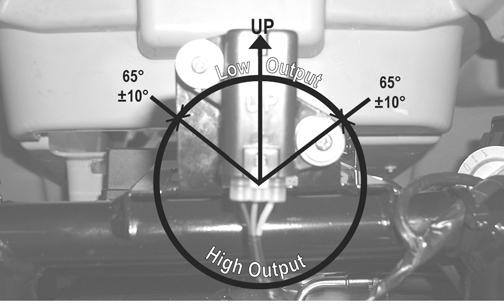
4.Tilt the sensor 60° or more to the left and right observing the meter. The meter should read 4.0-8.0
DC volts after approximately one second in the tilted position. If the meter readings are not as specified, the tilt sensor is defective.
CD709
NOTE: When replacing the sensor after testing,
make sure the arrow marking is directed up.
CD705A
Throttle Position Sensor (TPS)
NOTE: On the XTX, preliminary checks may be per-
formed on this component using the diagnostic mode on the LCD gauge (see EFI Diagnostic System in this section).
TESTING (XTX) 1.Remove the seats and center console; then disconnect the three-wire TPS connector plug.
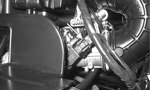
PR533A
NOTE: Prior to testing the TPS, inspect the
three-wire plug connector on the main harness and the three-pin plug on the TPS for contamination, broken pins, and/or corrosion.
NOTE: If the vehicle is in warranty, removing or
adjusting the TPS will void warranty. If the TPS is tested out of specification, the throttle body must be replaced. If the vehicle is out of warranty, the TPS may be adjusted.
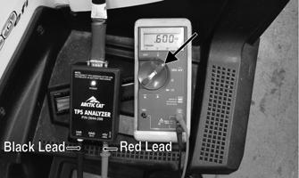
2.Connect the TPS Multi-Analyzer Harness connector #8 to the TPS; then connect the harness to the TPS
Analyzer Tool.
FI672
3.Using a multimeter, connect the black tester lead to the white socket (VAR) on the analyzer and the red tester lead to the red socket (+5V); then select the
DC Voltage position. With the vehicle off, the gauge should read 0.58-0.62 and at Wide-Open Throttle it should read up to approximately 3.7.
FI676A
TESTING (XT/XTZ) 1.Connect the main harness to the TPS.
2.Locate the diagnostic plug under the driver’s seat next to the PDM; then install the Test Plug from Test
Plug/Error Code List onto the plug. 3.Turn the ignition switch to the ON position and note the position of the TPS indicator icon (A, B, or C); then adjust the TPS until the TPS icon appears in the center position (B).
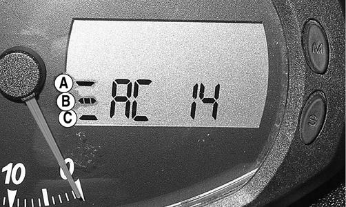
PR541B
4.Cycle the accelerator pedal to approximately half throttle six times; then return the accelerator pedal to idle.
The display should return to the center position (B). 4.Remove the test plug.
ECM Error Codes (XT/XTZ)
If a sensor fails or an out-of-tolerance signal is sensed by the ECM, an error code will be generated by the ECM. This will result in the analog needle swinging full scale. The EFI icon will flash.
To read the error code(s), use the following procedure. 1.Make sure the ignition switch is in the OFF position; then remove the seats.
2.Locate the diagnostic plug next to the PDM; then remove the black rubber cap. 3.Connect the Test Plug from Test Plug/Error Code
List to the diagnostic plug.
ATV-112
4.Turn the ignition switch to the ON position and read the error code on the LCD. Refer to the following Code
List to identify the specific problem area. Code List NOTE: Each of the following numerical codes will
have a two-letter prefix. A prefix of AC (Active Code) or SC (Stored Code) will be displayed. Always correct and clear Active Codes before clearing Stored Codes.
•00 =No Fault Detected (active code only) •12 =CKP (Crankshaft Position) Sensor* •13 =APS (Air Pressure Sensor) - H1 •13 =MAP (Manifold Absolute Pressure) Sensor - H2 •14 =TPS (Throttle Position Sensor) •15 =ECT (Engine Coolant Temperature) Sensor •16 =Speed Sensor •21 =IAT (Inlet Air Temperature) Sensor •23 =Tilt Sensor* •24 =Ignition Coil #1* •26 =Ignition Coil #2* - H2 •32 =Fuel Injector #1* •34 =Fuel Injector #2* - H2 •40 =ISC (Idle Speed Control) Valve •41 =Fuel Pump Relay* •60 =Cooling Fan Relay •95 =Sensor Power •96 =Incorrect ECM* •97 =ECM Memory Power (constant battery power) •98 =ECM to Gauge Comm Link - H2 •99 =Start/Run Not Possible (active code only)
*Will initiate code 99. After all stored codes are cleared, clear the error code(s) using the following procedure. NOTE: The ignition switch should be in the OFF
position.
1.With the test plug connected to the diagnostic plug and the drive select switch in the 4WD position, hold the reverse override switch down and turn the ignition switch to the ON position. 2.After ten seconds, release the reverse override switch and turn the ignition switch to the OFF position; then turn the ignition switch to the ON position. The display should read AC00 (no fault detected). NOTE: If the LCD still displays an error code, con-
tinue troubleshooting the appropriate component.
3.Disconnect the test plug; then install the black rubber cap. 4.Install the seats making sure they lock securely in place.
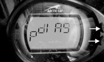
EFI Diagnostic System (XTX)
DIGITAL GAUGE The digital gauge can be used as a diagnostic tool for many of the DTC’s displayed. To place the gauge into the diagnostic mode, use the following procedure. 1.Turn the ignition switch ON. 2.Depress and hold both Mode and Set buttons together for approximately 10 seconds after which the letters “dIAg” will appear on the LCD momentarily followed by COOL.
EFI002A
NOTE: The display on the gauge will display in SAE
(speedometer in MPH mode) or Metric (speedometer in km/h mode), For example to read temperature in degrees Celsius, select km/h mode on the gauge or to read Fahrenheit, select MPH mode.
3.Cycle the display by depressing either the Set or
Mode button to step to the desired function.
EFI004
NOTE: The gauge can be utilized dynamically
(engine running/vehicle moving) or statically (engine/vehicle stopped).
Examples of Static checks: Battery voltage, fuel gauge/sensor, and TPS (0% @ closed throttle, 95-100% @ WOT).
EFI007
Examples of Dynamic checks: Battery charging, coolant temperature including fans ON/OFF (see below), MAP/IAT, tachometer, and speedometer signal.
EFI003
*Fan Schedule: Fan ON @ 185° F, OFF @ 175° F. *High Temperature REV Limiter 5000 RPM @ 230° F. *Thermostat opens @ approximately 180° F noted by a 2-5 degree drop momentarily.
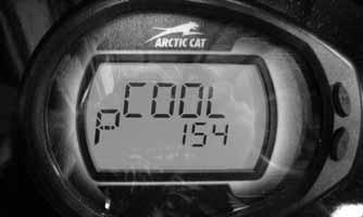
Coolant (COOL) Diagnostic Mode
EFI 003
Display: Engine coolant temperature as measured by the ECT sensor.
DTC: P0116, P0117, P0118, P0119 Usage: Monitor coolant temperature to verify the following. 1.ECT sensor signal 2.High Temperature indicator (on @ 230° F.) 3.Thermostat opening @ approximately 180° F, indicated by a momentary drop or pause in the rising temperature reading. 4.Fan ON @ 185° F, OFF @ 175° F.
A.fan motor
B.fan relay C.fan fuse
D.wiring connections 5.High Temperature Rev Limiter 5000 RPM @ 230° F.
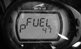
EFI010
Display: Fuel level signal from the fuel level sensor (measured in ohms). DTC: C1400 Usage: Check output of the fuel level sensor 1.Full fuel is indicated by a reading of 0-25 ohms 2. Empty is indicated by a reading of 98-100 ohms.
* 110-500 ohms, suspect the fuel level sensor or wiring * 0-100 ohms but no fuel gauge indication, suspect the fuel gauge
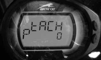
Tachometer (tACH) Diagnostic Mode
EFI009
Display: Engine RPM DTC: P0336, P0337, P0339 Usage: Verify engine speed signal from the following. 1.CKP (crankshaft position) sensor to ECM 2. ECM (CAN) signal to gauge (tachometer) 3. ECM (CAN) signal to EPS
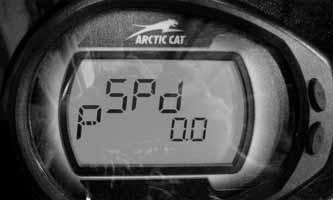
EFI008
Display: vehicle speed signal. DTC: P0500
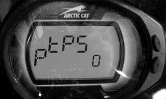
Usage: verify speedometer sensor signal from the following. 1.Speed sensor to ECM. 2.ECM (CAN) signal to gauge (speedometer/odometer). 3.ECM (CAN) signal to EPS unit. TPS (tPS) Diagnostic Mode
Display: % of TPS (0% closed, 95-100% WOT). DTC: P0121, P0122, P0123 Usage: Verify TPS signal and adjust throttle cable. MAP (bArO) Diagnostic Mode
EFI007
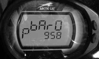
Display: MAP in millibars (1013 millibar = 29.92 in. mercury). DTC: P0107, P0108 Usage: Verify barometric pressure signal correct. Note: Local barometric pressure is given in in./Hg
(Inches of Mercury). 34 millibars are equal to 1 inch of mercury. Example: (Gauge reading in the BARO mode = 974 millibars, thus 974/34 = 28.64 in./Hg). Second example: (Local barometer reading is 29.87 in./Hg, therefore 29.87 X 34 = 1015 millibars) The gauge should be reading very close to 1015.
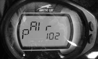
Inlet Air Temperature (AIr) Diagnostic Mode
EFI005
Display: Inlet air temperature in Fahrenheit or Celsius. DTC: P0112, P0113, P0114 Usage: Verify correct output of IAT sensor. NOTE: After engine has been running, IAT readings
will be higher than outside air temperature due to engine and engine compartment heat as well as intake manifold heating.
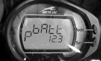
EFI004
Display: System DC voltage. DTC: P0562, P0563, P2531, P2532 Usage: Verify system voltage under following conditions. 1.Battery voltage with engine and accessories off (>12.2 VDC for fully charged). 2.Battery voltage with engine running (charging = 13.8
VDC or greater). 3.Battery voltage with electrical accessories operating, engine idling (13.5 VDC or greater). 4.Battery voltage starter cranking (10.5-11.5 VDC). DIAGNOSTIC TROUBLE CODES (DTC) If an EFI or related chassis component fails or an out-of-tolerance signal is detected by the ECM, a diagnostic trouble code (DTC) will be generated in the ECM and displayed on the LCD. The DTC will be displayed alternately with a wrench icon or malfunction indicator light (MIL). The DTC will continue to flash, until the malfunction is corrected and the code cleared.
Code List NOTE: Each of the following numerical codes will
have a one-letter prefix of C, P, or U. A “C” prefix denotes a chassis malfunction, a “P” prefix denotes a power train malfunction, and a “U” prefix denotes a loss of communication with the gauge.
NOTE: Normal malfunction codes are cleared from
the LCD when the component is replaced or the malfunction is corrected; however, intermittent codes must be cleared as noted in the code chart.
Code Fault Description Possible Cause Fault Recovery
C0063 Tilt Sensor Circuit High Sensor or interconnect harness shorted to battery power Correct condition* C0064 Tilt Sensor Circuit Low/SG/Open Sensor or interconnect harness open or shorted to chassis groundCorrect condition* C1263 Backup/Reverse-Light Circuit Open Bulb has failed or is disconnected or interconnect harness is openCorrect condition* C1264 Backup/Reverse-Light Circuit High Bulb has failed or is disconnected or interconnect harness shorted Correct condition* to battery power C1265 Backup/Reverse-Light Circuit Low/SG Bulb has failed or is disconnected or interconnect harness shorted Correct condition* to chassis ground P0030 O2 Heater Intermittent/Open Heater or interconnect harness is intermittent or open Correct condition* P0031 O2 Heater Low/SG Heater or interconnect harness shorted to chassis ground Correct condition* P0032 O2 Heater High/SP Heater or interconnect harness shorted to battery power Correct condition* P0107 MAP Sensor Circuit Low/SG/Open Sensor or interconnect harness shorted to chassis ground Correct condition* P0108 MAP Sensor Circuit High/SP Sensor or interconnect harness shorted to battery power Correct condition*
P0112 Intake Air Temp Sensor Circuit Low/SG Sensor or interconnect harness shorted to chassis ground Correct condition* P0113 Intake Air Temp Sensor Circuit High/Open Sensor or interconnect harness open or shorted to battery power Correct condition* P0114 Intake Air Temp Sensor Circuit Intermittent Sensor or interconnect harness intermittent Correct condition* P0116 ECT Sensor Circuit Range/Performance Sensor producing an out-of-range voltage Correct condition* P0117 ECT Sensor Circuit Low/SG Sensor or interconnect harness shorted to chassis ground Correct condition* P0118 ECT Sensor Circuit High/Open/SP Sensor or interconnect harness open or shorted to battery power Correct condition* P0119 ECT Sensor Circuit Intermittent Sensor or interconnect harness intermittent Correct condition* P0121 TPS Range/Performance Sensor producing an out-of-range voltage Correct condition* P0122 TPS Circuit Low/SG Sensor or interconnect harness shorted to chassis ground Correct condition* P0123 TPS Circuit High Sensor or interconnect harness open or shorted to battery power Correct condition* P0130 O2 Sensor Intermittent/Open Sensor or interconnect harness intermittent or open Correct condition* P0131 O2 Sensor Low/SG or Air-Leak Sensor or interconnect harness shorted to chassis ground or an Correct condition* air-leak exists P0132 O2 Sensor High/SP Sensor or interconnect harness shorted to battery power Correct condition* P0171 O2 Feedback Below Minimum Correction Low fuel rail pressure, dirty fuel filter, or dirty injectors Correct condition* P0172 O2 Feedback Exceeds Maximum CorrectionExcessive fuel rail pressure, MAP or temp sensors out-of-spec Correct condition* P0219 Engine Over-Speed Condition Engine speed (RPM) has exceeded the ECM over-speed set- Reduce engine speed point/limit P0231 Fuel Pump Relay Circuit Low/SG/Open Relay removed or interconnect harness shorted to chassis ground Correct condition* P0232 Fuel Pump Relay Circuit High Relay or interconnect harness shorted to battery power Correct condition* P0233 Fuel Pump Relay Circuit Relay circuit erratic or intermittent Correct condition* P0261 Cylinder #1 Fuel injector Circuit Low/SG Injector #1 or interconnect harness shorted to chassis ground Correct condition** P0262 Cylinder #1 Fuel injector Circuit High Injector #1 or interconnect harness shorted to battery power Correct condition** P0263 Cylinder #1 Fuel injector Balance/Open Injector #1 disconnected or interconnect harness is open Correct condition** P0264 Cylinder #2 Fuel injector Circuit Low/SG Injector #2 or interconnect harness shorted to chassis ground Correct condition** P0265 Cylinder #2 Fuel injector Circuit High Injector #2 or interconnect harness shorted to battery power Correct condition** P0266 Cylinder #2 Fuel injector Balance/Open Injector #2 disconnected or interconnect harness is open Correct condition** P0336 Crankshaft Angle Sensor Synchronization Sensor or interconnect harness intermittent Correct condition** P0337 Crankshaft Angle Sensor Circuit/SG Sensor or interconnect harness shorted to chassis ground Correct condition** P0339 Crankshaft Angle Sensor Intermittent/ErraticSensor or interconnect harness intermittent Correct condition** P0340 Camshaft Angle Sensor Synchronization Sensor or interconnect harness intermittent Correct condition** P0341 Camshaft Angle Sensor Circuit/SG Sensor or interconnect harness shorted to chassis ground Correct condition** P0342 Camshaft Angle Sensor Intermittent/Erratic Sensor or interconnect harness intermittent Correct condition** P0480 Fan Relay Control Circuit Relay erratic or intermittent Correct condition* P0484 Fan Relay Control Circuit High Relay or interconnect harness shorted to battery power Correct condition* P0485 Fan Relay Control Circuit Low/SG/Open Fan fuse has blown, fan relay removed, or interconnect harness Correct condition* shorted to chassis ground P0500 Vehicle Speed-Sensor Sensor circuit signal intermittent or missing Correct condition*, start and drive the vehicle* P0508 Idle Air Control System Circuit Low/SG IAC interconnect harness shorted to chassis ground Correct condition* P0509 Idle Air Control System Circuit High/Open IAC disconnected or the interconnect harness shorted to battery Correct condition* power P0520 Engine Oil Sensor/Switch Sensor or interconnect harness erratic or intermittent Correct condition* P0562 System Voltage Low Battery charge condition low or the regulator/rectifier output low Correct condition* P0563 System Voltage High Battery cable connections are loose or regulator/rectifier output highCorrect condition* P0601 ECM CAN Communication Shutdown Intermittent CAN connections or unstable CAN conditions have Correct CAN communicaused the ECM to temporarily shutdown CAN communication cation issue* P0615 Starter Relay Circuit Start switch/button, starter relay, gearswitch or interconnect harness Correct condition* erratic or intermittent P0616 Starter Relay Circuit Low Start switch/button, starter relay or interconnect harness intermittent Correct condition* or shorted to chassis ground P0617 Starter Relay Circuit High Start switch/button, starter relay or interconnect harness intermittent Correct condition* or shorted to battery power P0630 VIN Not Programmed or Incompatible Verify the LCD gauge and ECM part numbers are correct for the Correct gauge and ECM vehicle model number and VIN VIN compatibility issue* P0642 Sensor Power Circuit Low One or more of the sensors defective or shorted to chassis ground Correct condition* P0643 Sensor Power Circuit High One or more of the sensors defective or shorted to battery power Correct condition* P2300 Ignition Coil #1 Primary Circuit Ignition coil #1 or interconnect harness open or shorted to chassis Correct condition** Low/SG/Open ground P2301 Ignition Coil #1 Primary Circuit High Ignition coil #1 or interconnect harness shorted to battery power Correct condition** P2303 Ignition Coil #2 Primary Circuit Low/Open Ignition coil #2 or interconnect harness open or shorted to chassis Correct condition** ground P2304 Ignition Coil #2 Primary Circuit High Ignition coil #2 or interconnect harness shorted to battery power Correct condition** P2531 Ignition Switch Circuit Low Battery charge condition low or the regulator/rectifier output low Correct condition* P2532 Ignition Switch Circuit High Battery cable connections are loose or regulator/rectifier output highCorrect condition* U0155 LCD Gauge to EFI ECM CAN Communica- Gauge CAN circuit or interconnect harness intermittent or has failedCorrect condition* tion Lost U1000 Vehicle Not Registered or Invalid PIN An invalid registration PIN has been entered Enter the correct regisEntered tration PIN*
U1001 Vehicle Not Registered and Vehicle Limits An invalid registration PIN has been entered Enter the correct regisEnabled tration PIN* FUEL OFFTilt Sensor Activation Code Sensor activated Restore the vehicle chassis to an upright position*
High: A high voltage condition has been detected Low: A low voltage condition has been detected Intermittent: An intermittent circuit condition has been detected Open: An or open circuit condition has been detected * After correcting the condition, cycle the key switch On-Off-On **After correcting the condition, cycle the key switch On-Off-On, start the engine, then cycle the key switch Off-On.
Troubleshooting
Problem: Spark absent or weak Condition Remedy
1. Ignition coil defective 1.Replace ignition coil 2. Spark plug(s) defective 2.Replace plug(s) 3. CKP sensor defective 3.Replace CKP sensor 4. ECM defective 4.Replace ECM
Problem: Spark plug fouled with carbon
Condition Remedy 1. Gasoline incorrect 1.Change to correct gasoline 2. Air cleaner element dirty 2.Clean element 3. Spark plug(s) incorrect (too cold) 3.Replace plug(s) 4. Valve seals cracked - missing 4.Replace seals 5. Oil rings worn - broken 5.Replace rings
Problem: Spark plug electrodes overheat or burn Condition Remedy
1. Spark plug(s) incorrect (too hot) 1.Replace plug(s) 2. Engine overheats 2.Service cooling system 3. Spark plug(s) loose 3.Tighten plug(s)
Problem: Battery does not charge Condition Remedy
1. Lead wires/connections shorted - loose - open 1.Repair - replace - tighten lead wires 2. Stator coils shorted - grounded - open 2.Replace stator coils 3. Regulator/rectifier shorted 3.Replace regulator/rectifier
Problem: Battery charges, but charging rate is below the specification Condition Remedy
1. Lead wires shorted - open - loose (at terminals) 1.Repair - tighten lead wires 2. Stator coils grounded - open 2.Replace stator coils 3. Regulator/rectifier defective 3.Replace regulator/rectifier 4. Electrolyte low 4.Add distilled water 5. Cell plates (battery) defective 5.Replace battery
Problem: Magneto overcharges Condition Remedy
1. Internal battery short circuited 1.Replace battery 2. Regulator/rectifier defective 2.Replace regulator/rectifier 3. Regulator/rectifier poorly grounded 3.Clean - tighten ground connection
Problem: Charging unstable Condition Remedy
1. Lead wire intermittently shorting 1.Replace lead wire 2. Magneto internally shorted 2.Replace stator coil 3. Regulator/rectifier defective 3.Replace regulator/rectifier
Problem: Starter does not engage Condition Remedy
1. Battery charge low 1.Recharge - replace battery 2. Switch contacts defective 2.Replace switch 3. Starter motor brushes not seating 3.Replace starter 4. Starter relay defective 4.Replace relay 5. Emergency stop - ignition switch off 5.Turn on switches 6. Wiring connections loose - disconnected 6.Connect - tighten - repair connections 7. Start-in-gear/neutral relay defective 7.Replace relay
Problem: Battery “sulfation” (Acidic white powdery substance or spots on surfaces of cell plates) Condition Remedy
1. Charging rate too low - too high 1.Replace battery 2. Battery electrolyte insufficient 2.Keep electrolyte to prescribed level 3. Specific gravity too low 3.Charge battery - add distilled water 4. Battery discharged 4.Charge battery 5. Electrolyte contaminated 5.Replace battery
Problem: Battery discharges too rapidly Condition Remedy
1. Electrolyte contaminated 1.Replace battery 2. Specific gravity low 2.Charge battery - add distilled water 3. Charging system (charging operation) not set properly 3.Check AC generator - regulator/rectifier - circuit connections 4. Cell plates overcharged - damaged 4.Replace battery - correct charging system 5. Battery short-circuited 5.Replace battery 6. Electrical load too high 6.Reduce load
Problem: Battery polarity reversed Condition Remedy
1. Battery incorrectly connected 1.Reverse connections - replace battery