27 minute read
Steering/Frame/Controls

The following steering components should be inspected periodically to ensure safe and proper operation.
A.Steering wheel secure.
B.Steering has equal and complete full-left and full-right capability.
C.Steering sector mounting bolts tight.
D.Ball joints not worn, cracked, or damaged.
E.Tie rods not bent or cracked.
F.Knuckles not worn, cracked, or damaged.
G.Cotter pins not damaged or missing.
H.Steering wheel tilt locks securely (XTX). The frame and welds should be checked periodically for damage, bends, cracks, deterioration, broken components, and missing components.
Steering Assembly (XT)
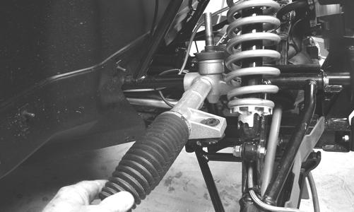
REMOVING 1.Secure the vehicle on a support stand to elevate the front wheels; then remove the front wheels.
2.Remove the cotter pins and nuts securing the tie rod ends to the knuckles; then remove the tie rod ends from the knuckles.
! WARNING
Make sure the vehicle is solidly supported on the support stand to avoid injury.
PR301
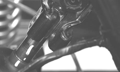
3.Make matching alignment marks on the pinion shaft and lower steering shaft joint.
PR333A
NOTE: Any time steering components are disas-
sembled, all connecting components should be marked for proper alignment during assembling.
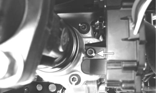
4.Remove the cap screw securing the lower steering shaft joint to the pinion shaft; then slide the joint free of the pinion.
PR302
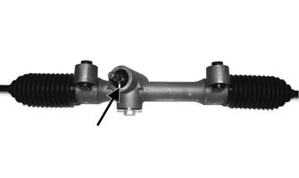
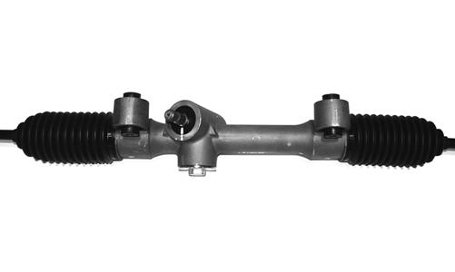
5.Remove two cap screws securing the rack and pinion assembly to the frame. Account for two nuts and two washers.
PR303A
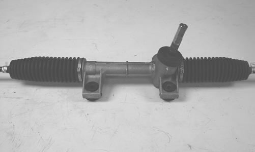
6.Remove the rack and pinion assembly from the right-side.
PR305
INSPECTING 1.Inspect the tie rod ends for damaged threads, torn boots, or excessive wear. 2.Inspect the tie rods for bends or deformation. 3.Inspect the rack and pinion-to-tie rod boots for tears or deterioration.
PR307
4.Check boot clamps for security. 5.Check that the rack and pinion assembly operates smoothly with no binding from full-left to full-right position. 6.Inspect for grease seepage from the rack and pinion assembly. NOTE: The steering assembly (rack and pinion) is
not repairable and must be replaced as an assembly; however, the tie rods and boots are replaceable.
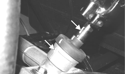
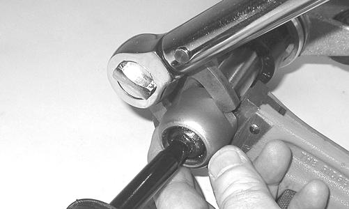
REPLACING TIE RODS/BOOTS 1.Secure the rack and pinion assembly in a vise or other suitable holding fixture; then remove the tie rod end, jam nut, and rack boot. 2.Slide the steering stopper (A) away from the inner tie rod end (B); then hold the rack (C) with a pipe wrench and remove the inner tie rod end from the rack.
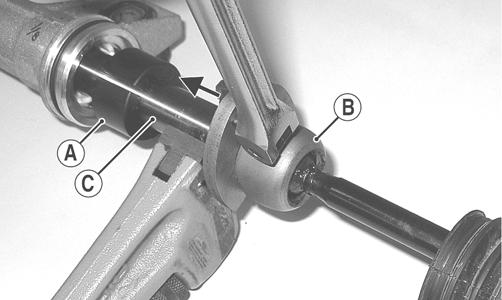
PR523A
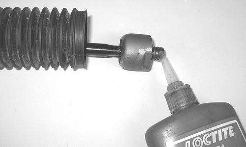
3.Clean all Loctite from the threads in the rack and if the tie rod is to be reused, clean the tie rod threads also.
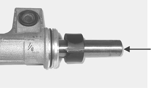
PR526A
4.Coat the thread with red Loctite #271; then install the tie rod into the rack and using an appropriate crow-foot, tighten to 52 ft-lb.
PR527
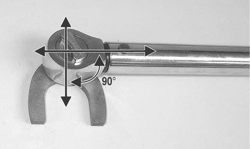
NOTE: Always attach the crow-foot to the torque
wrench with the open end 90° to the torque wrench handle to ensure accurate torque application.
PR528A
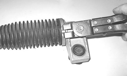
5.Install the rack boot and secure with the clamps; then loosely install the jam nut and outer tie rod end.
PR520
INSTALLING 1.Place the rack and pinion assembly into position from the right-side of the vehicle; then secure with the two cap screws, washers, and nuts. Tighten to 50 ft-lb.
PR305
2.With the rack and the steering wheel centered, slide the lower steering shaft joint onto the pinion shaft aligning the match marks.
PR309
3.Apply green Loctite #270 to the cap screw; then secure the lower steering shaft joint to the pinion shaft making sure the shaft does not protrude into the joint beyond the clamping surface.

PR309A
! WARNING
Allowing the lower steering shaft joint to extend too far onto the pinion shaft could cause binding or lock-up of the steering joint resulting in loss of steering control.
4.Tighten the cap screw to 36 ft-lb; then check that the steering wheel turns freely. 5.Install the tie rod ends into the steering knuckles; then secure with the castle nuts (coated with red Loctite #271) tightened to 30 ft-lb. 6.Install the cotter pins and spread to secure. 7.Install the wheels and tighten in a crisscross pattern in 20 ft-lb increments to 80 ft-lb (aluminum wheels) or 45 ft-lb (steel wheels). Check the steering system for full and free travel; then check and adjust the front wheel alignment (see Checking/Adjusting
Front Wheel Alignment in this section).
Electronic Power Steering (EPS) (XTX/XTZ)
REMOVING EPS ASSEMBLY NOTE: Thoroughly troubleshoot the EPS system
prior to replacing the EPS assembly (see the Electrical System section) as there are several possible external causes for system failure.
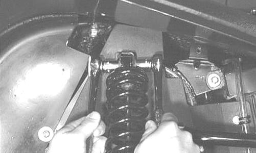
1.Support the vehicle on appropriate stands or a lift; then remove the left front wheel and left front shock absorber.
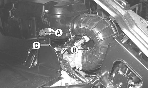
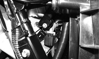
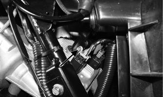
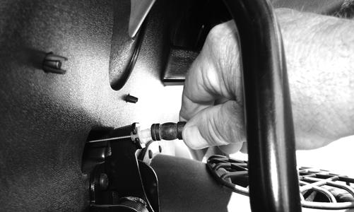
2.Remove the front storage box; then disconnect the two electrical connectors from the EPS assembly.

PR759A
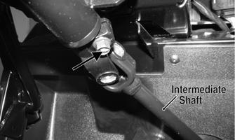
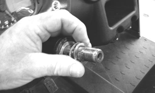
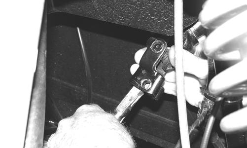
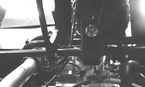
3.Remove the cap screw securing the intermediate shaft yoke to the EPS assembly input shaft.
PR760A
4.Remove the steering wheel; then remove the steering wheel boot support.
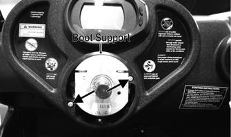
PR762A
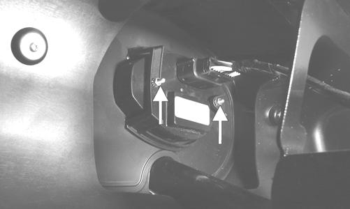
5.Remove the sheet metal screws securing the dash assembly to the frame; then disconnect the gauge plug and the dash harness. Remove the dash assembly. 6.Remove the four cap screws and nuts securing the steering shaft housing to the steering support; then remove the cap screw securing the intermediate shaft yoke to the steering shaft.
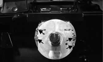
PR764A
PR765A
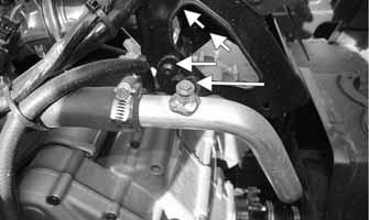
7.Remove the steering shaft housing and shaft from the steering support and intermediate shaft; then remove the intermediate shaft from the EPS input shaft. 8.Remove four cap screws securing the EPS assembly to the frame; then remove the cap screw securing the rack coupler to the EPS output shaft.
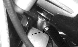
PR761A
NOTE: No repairs are authorized on the EPS assembly and it must be replaced as a complete assembly.
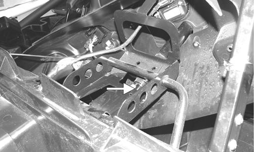
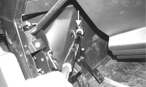
INSTALLING EPS ASSEMBLY 1.Align the slot in the rack coupler to the notch in the frame (front wheels centered).
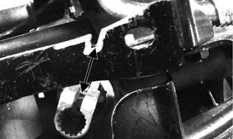
PR766A
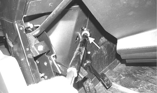
2.Rotate the EPS shaft to align the index (flattened) spline with the slot in the rack coupler.
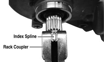
PR776A
NOTE: Alignment need only be approximate as final
alignment is not possible until the EPS is engaged with the coupler.
3.Install the EPS assembly into the coupler turning the
EPS shaft slightly to align the index spline; then seat the EPS firmly onto the frame. 4.Install four cap screws securing the EPS assembly to the frame and tighten to 35 ft-lb. 5.Install the cap screw in the EPS to rack coupler and tighten to 11 ft-lb. 6.Connect the two electrical connectors; then align the slot in the intermediate steering shaft coupler to the index (flattened) spline on the EPS input shaft and install. Install but do not tighten the cap screw. 7.Install the steering shaft housing with steering shaft connecting the steering shaft and intermediate shaft first; then slide the housing into place on the steering support. 8.Secure the steering shaft housing to the frame with four cap screws and nuts. Tighten the 6 mm nuts to 8 ft-lb and the 8 mm nuts to 20 ft-lb.

PR764B
9.Install the cap screw in the intermediate shaft coupler and tighten to 31 ft-lb; then tighten the cap screw (from step 6) to 11 ft-lb.
PR765A
10.Install the front storage box; then install the dash and connect the two electrical connectors. Secure with sheet metal screws and tighten securely. Do not over-tighten. 11.Install the steering housing boot; then install the boot support and secure with two machine screws. 12.Install the steering wheel; then apply a drop of red
Loctite #271 to the threads of the castle nut. Secure the steering wheel and tighten to 25 ft-lb. Install the safety pin and cover. REMOVING TIE RODS 1.Remove the steering rack assembly (see appropriate
Steering Assembly in this section). 2.Support the steering rack assembly in a suitable holding fixture or bench vise; then cut the securing band and slide the boot toward the outer tie rod end.
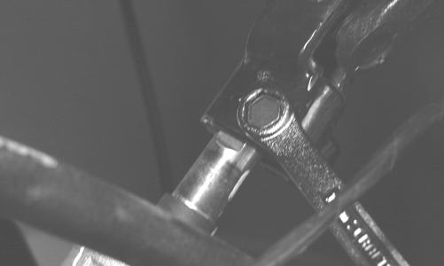
3.Using a punch or chisel, bend the lock washer away from the flats on the tie rod joint.
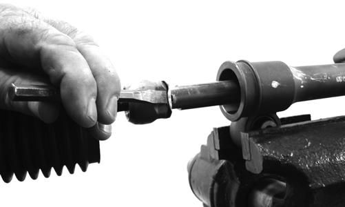
PR780
4.Using an appropriate crow-foot and backing wrench, remove the tie rod assembly. NOTE: Tie rods come as a complete assembly. No
further disassembly is required.
5.Remove and discard the lock washer.
INSTALLING TIE RODS 1.Remove the tie rod end and lock nut from the tie rod; then install the tie rod boot onto the tie rod.
2.Install the tie rod lock nut and tie rod end.
3.Coat the tie rod joint threads with red Loctite #271; then with a new lock washer, thread the tie rod into the rack.
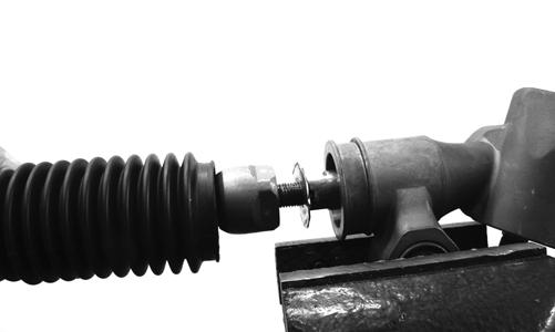
PR784
4.While holding the rack shaft with a wrench, tighten the tie rod joint to 37 ft-lb using an appropriate crow-foot.
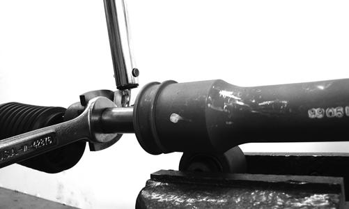
PR781
NOTE: Always attach the crow-foot to the torque
wrench with the open end 90° to the torque wrench handle to ensure accurate torque application.
PR528A
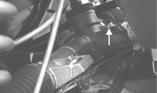
5.Install the boot onto the rack and secure with the nylon tie. 6.Center the rack in the steering rack assembly and align the white paint line on the pinion with the mark on the rack housing.
PR785A
Steering Assembly (XTX/XTZ)
REMOVING NOTE: The EPS assembly must be removed prior to
removing the steering assembly (see Electronic Power Steering (EPS) in this section).
1.Remove the EPS assembly; then remove the right front wheel.
2.Remove the cotter pins and nuts securing the tie rod ends to the knuckles; then remove the tie rod ends from the knuckles.
PR301
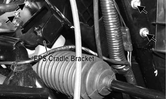
3.Remove the EPS cradle bracket; then remove the cap screws securing the steering rack assembly to the rack bracket and remove from the left side.
INSPECTING 1.Inspect the tie rod ends for damaged threads, torn boots, or excessive wear. 2.Inspect the tie rods for bends or deformation. 3.Inspect the rack and pinion-to-tie rod boots for tears or deterioration.
PR785
4.Check boot clamps for security. 5.Check that the steering assembly operates smoothly with no binding from full-left to full-right position. 6.Inspect for grease seepage from the steering assembly. NOTE: The steering assembly (rack and pinion) is
not repairable and must be replaced as an assembly; however, the tie rods and boots are replaceable.
INSTALLING 1.From the left side, install the steering assembly to the frame assembly and secure with two cap screws.
Tighten to 35 ft-lb. 2.Install the EPS cradle bracket and secure with four cap screws. Do not tighten the cap screws at this time.
PR773A
3.Place the tie rod ends into the knuckles and secure with the castle nuts (coated with red Loctite #271).
Tighten to 30 ft-lb; then install new cotter pins. NOTE: If the slots in the castle nut are not aligned
with the hole in the tie rod end, tighten until the cotter pin can be installed.
4.Install the EPS assembly (see Installing EPS Assembly sub-section this section); then tighten the cap screws (from step 2) to 20 ft-lb. 5.Install the wheel and tighten in a crisscross pattern in 20 ft-lb increments to 80 ft-lb (aluminum wheels) or 45 ft-lb (steel wheels).
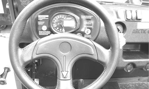
Steering Wheel
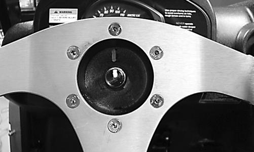
REMOVING 1.Remove the steering wheel cover; then match mark the steering shaft and steering wheel. NOTE: Any time steering components are disas-
sembled, all connecting components should be marked for proper alignment during assembling.
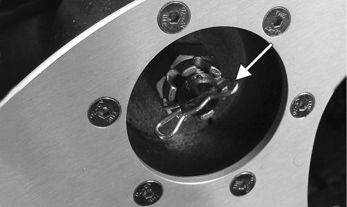
2.Remove the hairpin clip from the steering shaft; then remove the nut securing the steering wheel and remove the steering wheel. Account for the flat thrust washer and two wave washers.
PR226
INSPECTING 1.Inspect the steering wheel for cracks, missing padding, or broken spokes. 2.Inspect the splines for wear. 3.Check that the steering wheel is not bent. INSTALLING 1.Place the flat thrust washer and then the two wave washers onto the steering shaft. 2.Install the steering wheel aligning the two match marks; then apply a drop of red Loctite #271 to the threads of the nut and secure the steering wheel.
Tighten to 25 ft-lb. NOTE: If a new steering wheel is being installed,
mark the wheel as close as possible to the old wheel mark; then check for proper positioning with the front wheels straight forward.
3.Install the hairpin clip on the steering shaft. NOTE: If the hole in the steering shaft does not
align with the slots in the castle nut, tighten the nut slightly until the next slot aligns with the hole.
PR684A
Upper Steering Shaft
REMOVING 1.Remove the steering wheel. 2.Remove the screws securing the dash panel to the frame.
PR181A
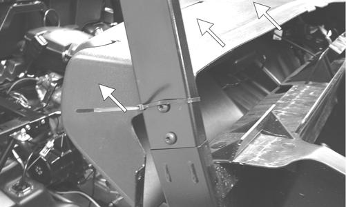
3.Slide the dash panel rearward to access the upper steering shaft joint; then remove the cap screw securing the upper shaft joint to the steering wheel shaft.
PR313A
4.Match mark the upper steering shaft joint and the steering wheel shaft; then remove the steering wheel shaft. Account for the lower thrust washer.
NOTE: Any time steering components are disas-
sembled, all connecting components should be marked for proper alignment during assembling.
INSPECTING 1.Inspect the steering wheel shaft for excessive wear. 2.Check for worn splines, cracks, or damaged threads. 3.Roll the steering wheel shaft on a flat surface to check for bends.
4.Inspect the nylon bushings in the steering shaft housing for cracking or excessive wear. INSTALLING 1.Slide the steering wheel shaft into the steering housing; then with the lower thrust washer in position, align the match marks and slide the upper steering shaft joint onto the steering wheel shaft.
PR313A
2.Apply green Loctite #270 to the cap screw; then install the cap screw in the upper steering shaft joint.
Install the nut and finger-tighten. 3.Align the match marks on the steering wheel shaft and the steering wheel and slide the steering wheel onto the splines; then install the nut and finger-tighten.
PR696
4.Hold rearward pressure on the steering wheel and tighten the cap screw (from step 2) to 36 ft-lb. 5.Remove the steering wheel nut. Apply one drop of red Loctite #271 to the threads and install the nut.
Tighten to 25 ft-lb; then install the hairpin clip. NOTE: If the hole in the steering shaft does not
align with the slots in the castle nut, tighten the nut slightly until the next slot aligns with the hole.
PR684A
6.Check for freedom of movement of the steering system; then install the steering wheel cover.
PR181A
Lower Steering Shaft Assembly
AT THIS POINT
Before beginning this procedure, the upper steering shaft must be removed.
REMOVING Remove the cap screw securing the lower steering shaft joint to the pinion shaft; then slide the steering shaft assembly free and remove through the opening in the splash panel.
PR304
PR314B
INSPECTING NOTE: The lower steering shaft assembly is not
repairable or rebuildable. If any damage or excessive wear is detected, the assembly must be replaced.
1.Inspect the joints for excessive wear or looseness. 2.Inspect welds and slip-joints for cracks. 3.Check for excessive wobble in the slip-joint. INSTALLING 1.Place the steering shaft assembly into position through the opening in the splash panel.
PR314A
2.Align the match marks on the pinion shaft and the lower steering shaft joint; then slide the steering shaft joint onto the pinion shaft.
PR333A
3.Apply green Loctite #270 to the cap screw; then secure the lower steering shaft joint to the pinion shaft making sure the pinion shaft does not protrude into the joint beyond the clamping surface. Tighten to 36 ft-lb.
PR309A
! WARNING
Allowing the lower steering shaft joint to extend too far onto the pinion shaft could cause binding or lock-up of the steering joint resulting in loss of steering control.
4.Install the upper steering shaft.
Steering Knuckles
REMOVING AND DISASSEMBLING 1.Secure the vehicle on a support stand to elevate the wheel; then remove the wheel.
! WARNING
Make sure the vehicle is solidly supported on the support stand to avoid injury.
2.Remove the cotter pin from the axle. 3.Remove the nut securing the hub. 4.Remove the brake caliper. 5.Remove the hub assembly. 6.Remove the cotter pin from the tie rod end and remove the tie rod end from the knuckle.
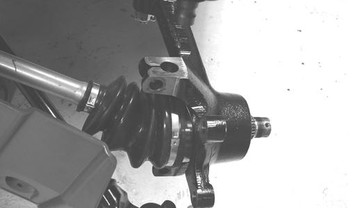
7.Remove the two cap screws securing the ball joints in the knuckle.

PR193
8.Tap the ball joint end out of the knuckle; then remove the knuckle.
PR289
CLEANING AND INSPECTING 1.Clean all knuckle components. 2.Inspect the bearing for pits, scoring, rusting, or premature wear.
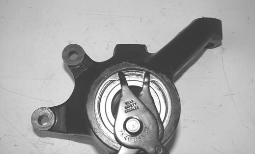
3.Inspect the knuckle for cracks, breaks, or galling of the bearing surface. ASSEMBLING AND INSTALLING 1.Using a suitable press and driver, press the bearing into the knuckle until firmly seated; then install the snap ring.
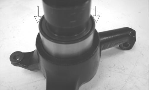
PR292A
PR289
2.Install the knuckle to the upper and lower ball joints and secure with the two cap screws. Tighten to 35 ft-lb.
PR202
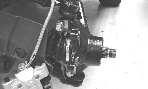
PR203
3.Install the tie rod end and secure with the nut (coated with red Loctite #271). Tighten to 30 ft-lb; then install a new cotter pin and spread the pin. NOTE: During assembling, new cotter pins should
be installed.
4.Apply a small amount of grease to the hub splines.
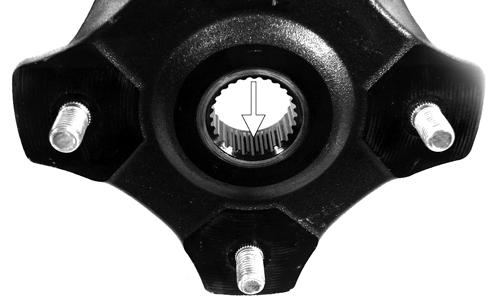
PR290A
5.Install the hub assembly onto the splines of the shaft.
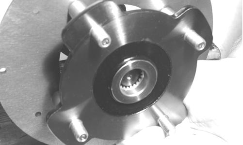
CD009
6.Using Hub Retaining Wrench, secure the hub assembly with the nut. Tighten to 200 ft-lb.
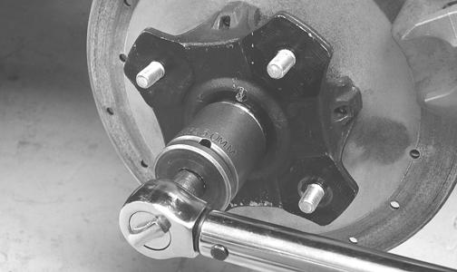
PR256
7.Install a new cotter pin and secure by spreading as shown.
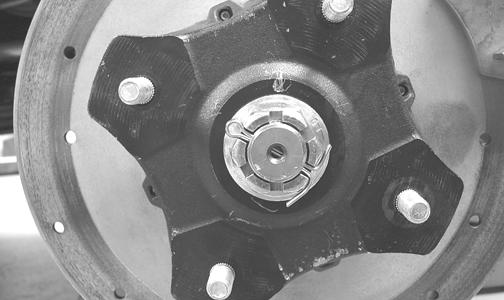
PR260
NOTE: If the hole in the axle shaft does not align
with the slots in the castle nut, tighten the nut until the hole and slots align.
8.Secure the brake caliper to the knuckle with the two new “patch-lock” cap screws. Tighten to 20 ft-lb.
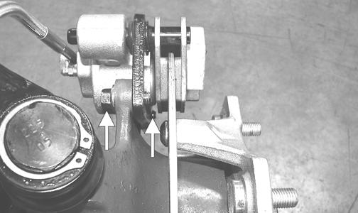
PR377B
9.Install the wheel; then tighten in a crisscross pattern in 20 ft-lb increments to 80 ft-lb (aluminum wheels) or 45 ft-lb (steel wheels). 10.Remove the vehicle from the support stand.
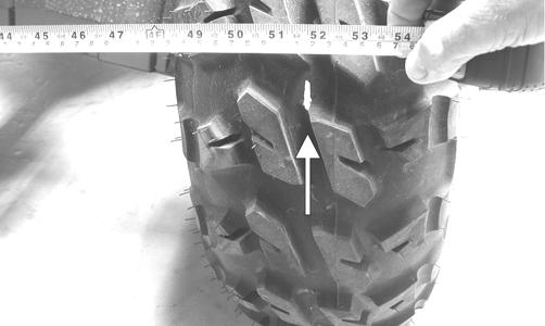
Checking/Adjusting Front Wheel Alignment
NOTE: All measurements and adjustments must be
made with the vehicle unloaded.
Mark the center-line of the front tires at the front and rear of the tire; then using a tape measure, measure and record the distance between the marks at the front and rear. The front measurement should be 6-12 mm (1/4-1/2 in.) greater than the rear measurement (toe-out).
PR087A
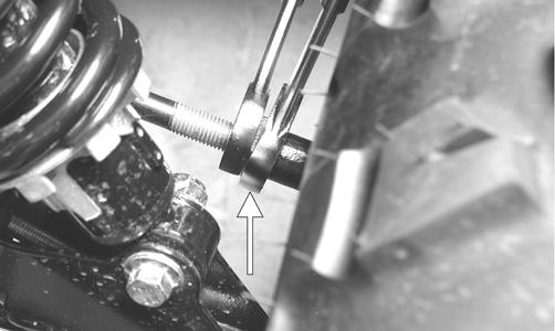
To adjust the wheel alignment, use the following procedure.
1.Center the steering wheel; then using an open-end wrench to hold the tie rod ends, loosen the right-side and left-side jam nuts.
PR084A
PR085A
CAUTION
Always use a wrench to hold the tie rod ends when loosening or tightening the jam nuts or damage to the boots could occur.
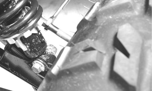
2.Turn the left-side and right-side tie rods in equal increments to achieve the proper toe-out; then tighten the jam nuts to 10 ft-lb.
PR086
Front Bumper Assembly
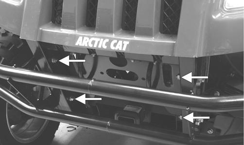
REMOVING Remove four cap screws and nuts. Account for four lock washers and eight flat washers.
PR327A
CLEANING AND INSPECTING 1.Clean all bumper components with hot, soapy water. 2.Inspect all welds for cracking or bending. INSTALLING Place the bumper assembly into position on the frame; then secure with the four cap screws and nuts making sure the flat washers and lock washers are properly positioned. Tighten to 35 ft-lb.
Hood
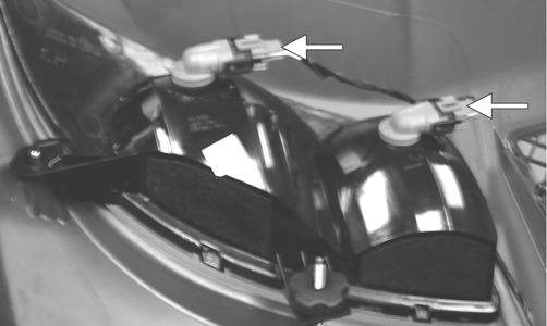
REMOVING 1.Open the hood; then disconnect the four headlight connectors and remove two nylon ties.
PR328A
2.Loosen but do not remove the four cap screws and flange nuts securing the hood hinge to the frame; then lower the hood.
PR332A
3.Finish removing the cap screws and flange nuts (from step 2); then remove the hood assembly. CLEANING AND INSPECTING 1.Clean all hood components with soap and water. 2.Inspect the hood for cracks and/or loose fasteners. 3.Inspect for any missing decals. INSTALLING 1.Place the hood into position on the vehicle; then install the two outside cap screws and flange nuts.
Finger-tighten only at this time. 2.Open the hood; then install the remaining two cap screws and flange nuts. Tighten all four securely.

PR332
3.Connect the four headlight connectors; then secure the wires with two new nylon ties.
PR332B
Fenders
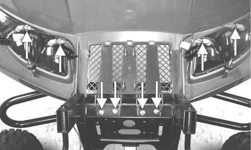
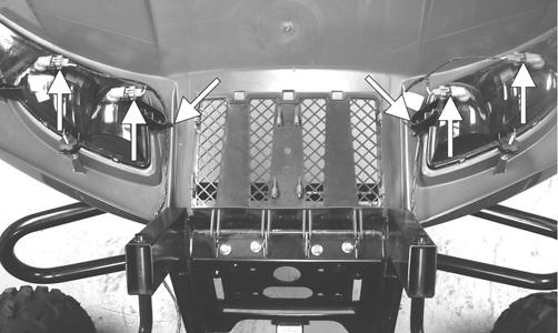
REMOVING Remove three torx-head screws securing each fender to the frame. Account for a stiffener bracket on the front fenders.
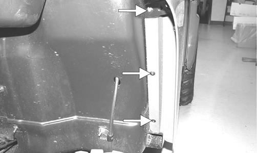
PR311A
INSTALLING Place the appropriate fender into position and secure with existing hardware.
Floor
REMOVING 1.Remove the seats and center console.
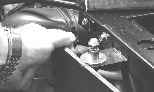
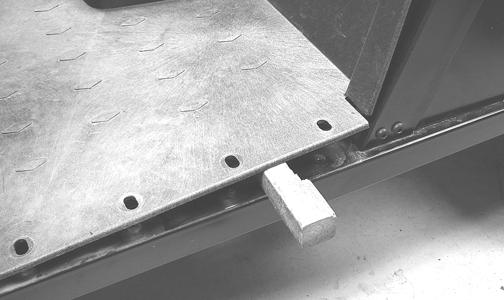
2.Remove the cap screws and self-tapping screws securing the floor to the frame. 3.While pulling forward on the upper-rear of the floor, lift the rear part of the floor above the seat lock stud. NOTE: To aid in removing, insert a small wood
block to hold in position.
PR163
PR164
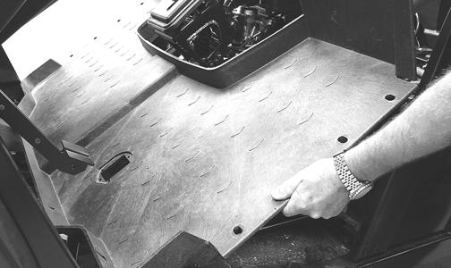
4.From the opposite side of the vehicle repeat step 3; then lift the rear of the floor up and lift the floor out of the vehicle.
PR165
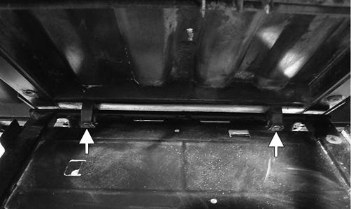
CLEANING AND INSPECTING 1.Clean the floor with soap and water. 2.Inspect the floor for cracks or holes. INSTALLING 1.Place the front of the floor into position in the vehicle first; then lower the rear and push past the seat lock studs.
2.Secure the floor with the cap screws and self-tappings screws. 3.Install the center console and seats making sure the seats lock securely into position.
Belly Panel
REMOVING 1.Remove the body screws securing the belly panel to the underside of the frame.
2.Remove the belly panel. INSTALLING 1.Place the belly panel into position on the underside of the frame.
Accelerator Pedal
REMOVING Dislodge the throttle cable holding grommet from the actuator arm; then remove two torx-head screws and nuts securing the accelerator pedal assembly to the splash panel and remove the accelerator pedal.
PR709

UTV354
INSTALLING Align the mounting holes with the holes in the splash panel and secure with the two torx-head screws and nuts; then snap the throttle cable holding grommet into the actuator arm.
Shift Lever (XT/XTZ)
REMOVING 1.Remove the seats and center console.
2.Remove the flange nut and shoulder screw from the shift lever pivot; then remove the shift lever.
Account for the shifter spring.
PR340
INSTALLING 1.With the shifter spring in place on the shift lever, install the shift lever onto the shift axle.
2.Install the shoulder screw and secure with the flange nut (threads coated with blue Loctite #243). Tighten to 20 ft-lb.
Shift Lever (XTX)
REMOVING 1.Remove the seats and center console; then remove the shift lever grip. 2.Remove the flange nut securing the shift cable to the shift arm.
3.Remove the cap screws securing the shift axle to the frame and remove the shift assembly. Account for two shift axle retainer plates.
PR819B
INSTALLING 1.Place the shift assembly into position and secure with two shift axle retainer plates and four cap screws. Tighten securely. 2.Connect the shift cable to the shift arm and secure with the flange nut. Tighten securely. 3.Install the jam nut and shift lever grip and tighten securely; then check for proper shifter operation (see
Periodic Maintenance - Shift Lever/Shift Cable (XTX)).
LCD Gauge/Indicator Lights
REPLACING 1.Remove the six screws securing the dash panel to the frame; then remove the parking brake handle and jam nut. 2.Slide the dash panel to the rear sufficiently to access the components.
PR181A
3.Disconnect the multi-pin connector; then remove the nuts securing the gauge assembly to the dash.
Remove the gauge from the vehicle.
PR284A
4.Place the new gauge into the dash panel opening; then place the gauge holder over the mounting screws and secure with the nuts.
5.Plug the multi-pin connector into the gauge; then turn the ignition switch to the ON position and check gauge functions. 6.Slide the dash into position and secure with the six screws.
7.Install the parking brake handle and jam nut.
Exhaust System
REMOVING MUFFLER 1.Remove the two exhaust springs at the muffler/exhaust pipe juncture.
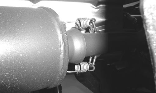
PR131
2.Slide the muffler assembly clear of the holder pins. INSPECTING MUFFLER 1.Inspect muffler externally for cracks, holes, and dents. 2.Inspect the muffler internally by shaking the muffler back and forth and listening for rattles or loose debris inside the muffler.
NOTE: For additional details on cleaning the muf-
fler/spark arrester, see the Periodic Maintenance section.
INSTALLING MUFFLER 1.Place the muffler onto the holder pins and slide into position. 2.Secure the muffler to the exhaust pipe with the two exhaust springs.
Cargo Box
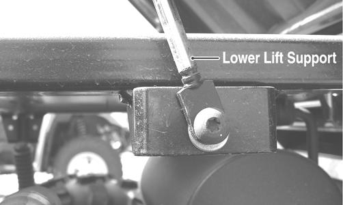
REMOVING 1.Raise the cargo box; then remove the cap screw and nut securing the lower lift support to the frame.
Account for the washer. The cargo box will tilt fully rearward.
PR473A
2.Loosen but do not remove the four shoulder cap screws securing the pivot housings to the cargo box.
PR793A
3.Lower the cargo box; then remove the four cap screws (from step 2). 4.With the help of an assistant or an adequate lift, remove the cargo box from the vehicle. Account for four pivot housings. CLEANING AND INSPECTING 1.Clean all cargo box components with soap and water. 2.Inspect the cargo box for cracks, tears, and loose hardware.
3.Inspect the welds of the cargo box frame for cracking or bending. 4.Inspect the cargo box gate latches for smooth operation. INSTALLING 1.With the help of an assistant or an adequate lift, set the cargo box into position on the frame; then position the two upper pivot housings between the cargo box and frame. Lightly grease the pivot housings. 2.Align the holes in the upper pivot housings with the holes in the cargo box; then install the lower pivot housings and secure with the four shoulder cap screws. Tighten to 20 ft-lb. 3.Raise the cargo box; then connect the lift support to the frame, install the cap screw and nut, and tighten the nut securely. 4.Lower the cargo box and lock into position.
Taillight Assembly
REMOVING 1.Remove two torx-head screws securing the taillight assembly to the rear ROPS tube; then rotate the taillight assembly left or right to allow the connector to clear the access opening. 2.Disconnect the three-prong connector from the bulb socket and remove the taillight assembly. INSPECTING 1.Inspect wiring harness, three-prong connector, lens, base, cap screws, and socket for damage. 2.Inspect all wires for corroding, pinching, and cracking. 3.Inspect the bulb for wattage, voltage, and proper operation. INSTALLING 1.Connect the three-prong connector to the bulb socket; then place the taillight assembly into position on the rear ROPS tube.
2.Install the two torx-head screws and tighten securely.
Seats
REMOVING/INSTALLING 1.To remove a seat, pull the seat lock lever up. Raise the front of the seat and slide it forward.
2.To install a seat, slide the rear of the seat into the seat retainers and push down firmly on the front of seat.
The seat should automatically lock into position.
Troubleshooting
Problem: Handling too heavy or stiff Condition Remedy
1. Front wheel alignment incorrect 1.Adjust alignment 2. Lubrication inadequate 2.Lubricate appropriate components 3. Tire inflation pressure incorrect 3.Adjust pressure 4. Tie rod ends seizing 4.Replace tie rod ends 5. Linkage connections seizing 5.Repair - replace connections
Problem: Steering oscillation Condition Remedy
1. Tires inflated unequally 1.Adjust pressure 2. Wheel(s) wobbly 2.Replace wheel(s) 3. Wheel hub cap screw(s) loose - missing 3.Tighten - replace cap screws 4. Wheel hub bearing worn - damaged 4.Replace bearing 5. Tie rod ends worn - loose 5.Replace - tighten tie rod ends 6. Tires defective - incorrect 6.Replace tires 7. A-arm bushings damaged 7.Replace bushings 8. Bolts - nuts (frame) loose 8.Tighten bolts - nuts
Problem: Steering pulling to one side Condition Remedy
1. Tires inflated unequally 1.Adjust pressure 2. Front wheel alignment incorrect 2.Adjust alignment 3. Wheel hub bearings worn - broken 3.Replace bearings 4. Frame distorted 4.Repair - replace frame 5. Shock absorber defective 5.Replace shock absorber
Problem: Steering impaired Condition Remedy
1. Tire pressure too high 1.Adjust pressure 2. Steering linkage connections worn 2.Replace connections 3. Cap screws (suspension system) loose 3.Tighten cap screws
Problem: Tire wear rapid or uneven Condition Remedy
1. Wheel hub bearings worn - loose 1.Replace bearings 2. Front wheel alignment incorrect 2.Adjust alignment
Problem: Steering noise Condition Remedy
1. Caps screws - nuts loose 1.Tighten cap screws - nuts 2. Wheel hub bearings broken - damaged 2.Replace bearings 3. Lubrication inadequate 3.Lubricate appropriate components
Problem: Rear wheel oscillation Condition Remedy
1. Rear wheel hub bearings worn - loose 1.Replace bearings 2. Tires defective - incorrect 2.Replace tires 3. Wheel rim distorted 3.Replace rim 4. Wheel hub cap screws loose 4.Tighten cap screws 5. Parking brake adjusted incorrectly 5.Adjust parking brake 6. Rear suspension arm-related bushing worn 6.Replace bushing 7. Rear shock absorber damaged 7.Replace shock absorber 8. Rear suspension arm nut loose 8.Tighten nut