24 minute read
Fuel/Lubrication/Cooling

NOTE: Arctic Cat recommends the use of new gas-
kets, lock nuts, and seals and lubricating all internal components when servicing the engine/transmission.
SPECIAL TOOLS A number of special tools must be available to the technician when performing service procedures in this section. Refer to the current Special Tools Catalog for the appropriate tool description.
Description p/n
Oil Pressure Test Kit 0644-495 Tachometer 0644-275
NOTE: Special tools are available from the Arctic
Cat Service Department.
Electronic Fuel Injection (XT/XTX)
! WARNING
Whenever the gasline hoses are removed (other than for pressure testing), the battery must be disconnected to prevent inadvertent activation of the electronic fuel pump.
! WARNING
Whenever any maintenance or inspection is performed on the fuel system during which there may be fuel leakage, there should be no welding, smoking, open flames, etc., in the area.
TROUBLESHOOTING 1.Verify that the electric fuel pump is operating by listening for a “whirring” sound for approximately three seconds after the ignition switch is turned to the
ON position. If no sound can be heard, see Electric
Fuel Pump/Fuel Level Sensor in this section. 2.Check for a flashing EFI icon on the LCD. If EFI is flashing, see ECM Error Codes in the Electrical System section.
3.Make sure there is sufficient, clean gas in the gas tank.
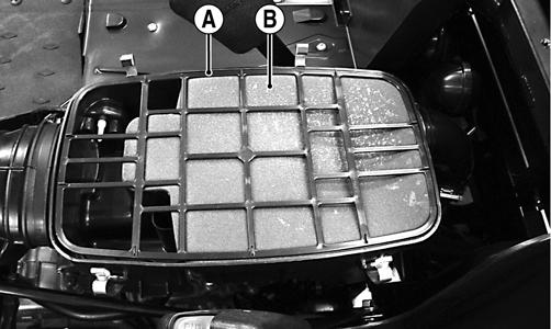
4.Verify that the battery is sufficiently charged to crank the engine over at normal speed. 5.Check the air filter housing and air filter for contamination. Clean or replace as necessary (see the Periodic Maintenance section). REMOVING THROTTLE BODY 1.Turn the ignition switch to the OFF position; then remove the ignition switch key.
! WARNING
Do not turn the ignition switch to the ON position with the hoses removed. Gasoline will be pumped by the electric fuel pump causing a safety hazard.
2.Remove the left and right seats; then remove the center console and disconnect the battery. 3.Remove the connector from the IAT sensor (A); then loosen the inlet boot clamp (B) and remove the mounting screw (C).
PR486A
4.Disconnect the crankcase breather hose from the air filter housing; then remove the air filter assembly from the vehicle.
PR487A
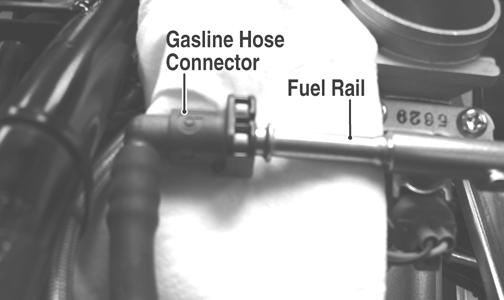
5.Slowly disconnect the gasline hose connector from the fuel rail.
! WARNING
Gasoline may be under pressure. Place an absorbent towel under the connector to absorb any gasoline spray when disconnecting.
FI092A
6.Remove the screw securing the throttle actuator cover to the throttle body; then remove the cover. 7.Remove the throttle cable from the actuator arm.
8.Loosen the outer jam nut securing the throttle cable to the throttle body; then route the cable out of the way. 9.Remove the electrical connectors from the throttle body components. 10.Remove the throttle body assembly from the intake pipe.
FI104A
11.Use tape to cover and seal the intake opening.
INSTALLING THROTTLE BODY 1.Install the throttle body into the intake pipe and secure with the clamp. Tighten securely. 2.Place a new O-ring in the intake pipe; then position the pipe onto the engine and secure with two cap screws.
3.Connect the throttle cable to the throttle body and adjust throttle cable free-play; then connect the gasline hose. 4.Connect the electrical connectors to the throttle body components. 5.Install the air filter assembly and secure with the existing hardware; then connect the IAT sensor and crankcase breather hose.
6.Install the center console and seats making sure the seats lock securely in place.
CAUTION
Any objects or liquid entering the intake opening will fall into the engine causing severe damage if the engine is turned over or started.
Electronic Fuel Injection (XTZ)
! WARNING
Whenever the gasline hoses are removed (other than for pressure testing), the battery must be disconnected to prevent inadvertent activation of the electronic fuel pump.
! WARNING
Whenever any maintenance or inspection is performed on the fuel system during which there may be fuel leakage, there should be no welding, smoking, open flames, etc., in the area.
TROUBLESHOOTING 1.Verify that the electric fuel pump is operating by listening for a “whirring” sound for approximately three seconds after the ignition switch is turned to the
ON position. If no sound can be heard, see Electric
Fuel Pump/Fuel Level Sensor in this section. 2.Check for a flashing EFI icon on the LCD. If EFI is flashing, see ECM Error Codes in the Electrical System section.
3.Make sure there is sufficient, clean gas in the gas tank.
4.Verify that the battery is sufficiently charged to crank the engine over at normal speed. 5.Check the air filter housing and air filter for contamination. Clean or replace as necessary (see the Periodic Maintenance section). REMOVING THROTTLE BODY 1.Turn the ignition switch to the OFF position; then remove the ignition switch key.
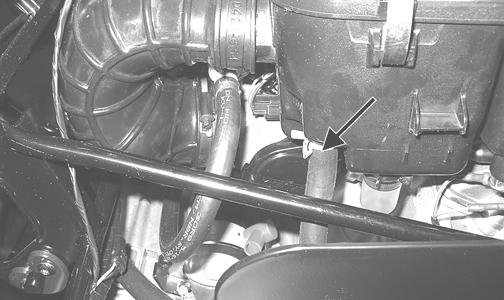
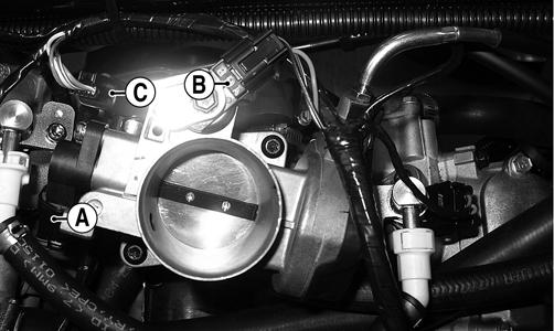
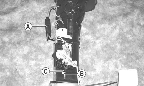
2.Remove the left and right seats; then remove the center console and disconnect the battery. 3.Remove the air inlet boot; then disconnect the throttle position sensor (TPS) connector (A), manifold absolute pressure (MAP) sensor connector (B), and idle speed control (ISC) connector (C).
! WARNING
Do not turn the ignition switch to the ON position with the hoses removed. Gasoline will be pumped by the electric fuel pump causing a safety hazard.
GZ094E
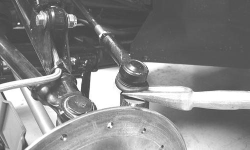
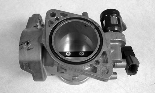
4.Remove the cap screws securing the throttle body to the manifold; then lift the throttle body off the manifold. Account for an O-ring.
GZ386
5.Remove the screw securing the throttle actuator cover to the throttle body; then remove the cover. 6.Remove the throttle cable from the actuator arm.
7.Loosen the outer jam nut securing the throttle cable to the throttle body. The throttle body can now be removed from the vehicle.
8.Use tape to cover and seal the intake opening.
INSTALLING THROTTLE BODY 1.Connect the throttle cable to the throttle body and adjust throttle cable free-play; then install the throttle actuator cover and secure with the machine screw.
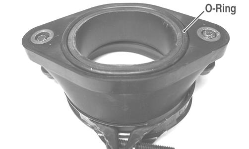
2.Remove the covering from the intake manifold opening; then using a new O-ring, install the throttle body onto the manifold and secure with the cap screws.
Tighten securely.
CAUTION
Any objects or liquid entering the intake opening will fall into the engine causing severe damage if the engine is turned over or started.
GZ386
3.Connect the TPS connector (A), MAP sensor connector (B), and ISC connector (C) to the throttle body; then install the air inlet boot and tighten the clamps securely.
GZ094E
4.Install the center console and seats making sure the seats lock securely in place.
Gas Tank
! WARNING
Whenever any maintenance or inspection is made on the fuel system during which there may be fuel leakage, there should be no welding, smoking, open flames, etc., in the area.
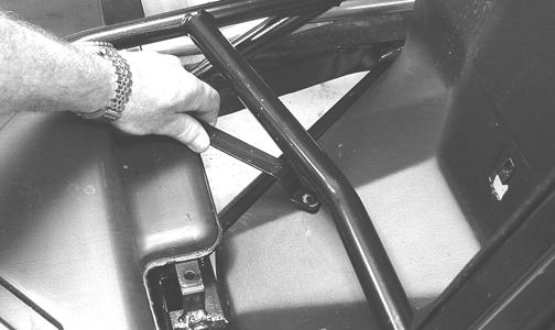
REMOVING 1.Remove the seats and center console; then remove the left-side and right-side seat-bases. 2.Remove twelve cap screws and two self-tapping screws securing the floorboard to the frame. 3.While pulling forward on the upper portion of the floorboard, lift the rear panel above the seat lock studs; then insert a small wood block to hold in position.
PR163
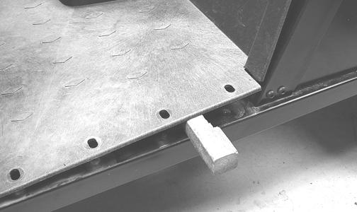
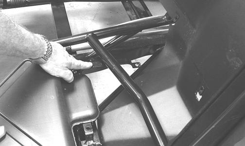
PR164
4.From the opposite side of the vehicle, repeat step 3; then lift the rear of the floorboard up and lift the floorboard out of the vehicle.
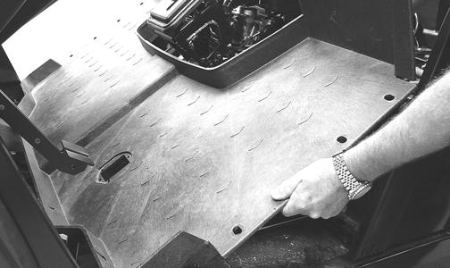
PR165
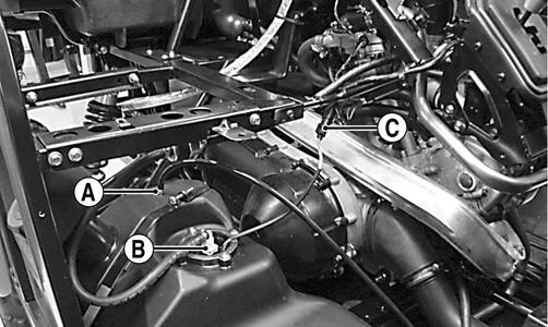
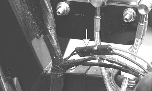
5.Disconnect the vent hose (A), gasline hose (B), and fuel pump/fuel level sensor connector (C); then cap the vent fitting and gas hose fitting.
PR167A
PR170
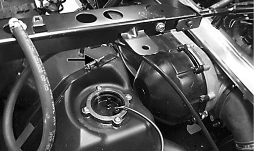
7.Remove four press-nuts securing the gas cap inset; then remove the gas cap and inset. Install the gas cap.
PR168
8.Remove the joining cap screw and nut from the rear gas tank hold-down strap; then remove the inside hold-down strap.
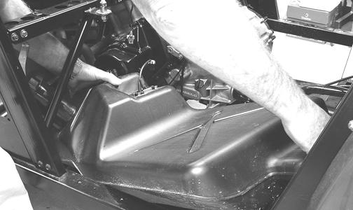
9.Lift and slide the tank forward raising the front of the tank first; then turn the tank and lift out the right side.
CLEANING AND INSPECTING 1.Clean all gas tank components with parts-cleaning solvent.
2.Inspect all hoses for cracks or leaks. 3.Inspect gas tank cap and tank for leaks, holes, and damaged threads. 4.Inspect the fuel level sensor for proper operation (see
Fuel Level Sensor in this section). INSTALLING 1.Place the gas tank into position in the vehicle; then install the inside rear hold-down strap.
PR173
PR699A
2.Swing the front hold-down to the right into position and install the cap screw and nut. Do not tighten at this time.
PR699A
4.Place the gas cap filler panel into position; then if necessary, position the gas tank so the filler panel and filler neck are not binding or rubbing.
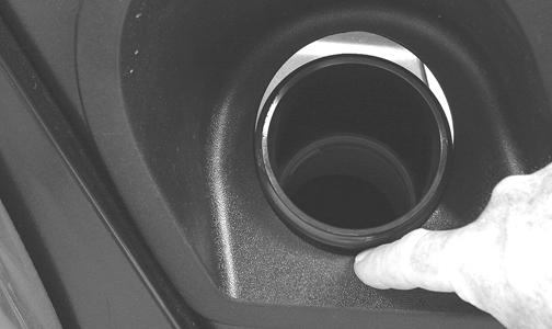
PR176
5.Secure the filler panel with four press-nuts; then tighten the hardware securing the hold-down straps (from steps 2-3) securely.
PR166A
PR167A
6.Connect the vent hose (A) and gasline hose (B) to the proper fittings; then connect the fuel pump/fuel level sensor connector (C) to the main harness.
PR698A
7.Position the floorboard into the vehicle and secure with the appropriate hardware; then install the center console, seat-bases, and seats making sure the seats lock securely.
Gas/Vent Hoses
Replace the gas hose every two years. Damage from aging may not always be visible. Do not bend or obstruct the routing of the vent hoses. Make certain the vent hoses are securely connected and the opposite ends are always open.
Oil Filter/Oil Pump
NOTE: Whenever internal engine components wear
excessively or break and whenever oil is contaminated, the oil pump should be replaced.
TESTING OIL PUMP PRESSURE (XT/XTX) NOTE: The engine must be warmed up to operating
temperature (cooling fan cycling) for this test.
1.Remove the seats and center console; then remove the left-side seat-base. 3.Remove the upper plug from the base of the oil filter; then using an appropriate adapter, connect an oil pressure gauge to the engine.
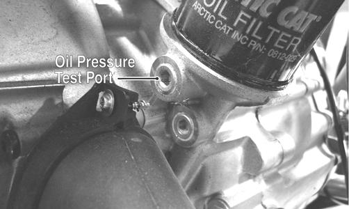
CF264A
NOTE: Some oil seepage may occur when installing the oil pressure gauge. Wipe up oil residue with a cloth.
4.Set the parking brake and start the engine. Allow the engine to warm up to operating temperature (with cooling fan cycling). 5.Set the speedometer/tachometer to RPM. With the engine running at 3000 RPM, the pressure gauge must show 0.6-0.7 kg/cm2 (8.5-10 psi), on the XT or 1.2-1.5 kg/cm2 (17-21 psi) on the XTX. 6.Install the left-side seat-base; then install the center console and seats making sure the seats lock securely. NOTE: If the oil pressure is lower than specified,
check for an oil leak, damaged oil seal, or defective oil pump.
NOTE: If the oil pressure is higher than specified,
check for too heavy engine oil weight (see General Information - Gasoline - Oil - Lubricant), clogged oil passage, clogged oil filter, or improper installation of the oil filter.
TESTING OIL PUMP PRESSURE (XTZ) NOTE: The engine must be warmed up to operating
temperature (cooling fan cycling) for this test.
1.Remove both seats and center console; then remove the oil hose from the fitting nearest the oil filter base.
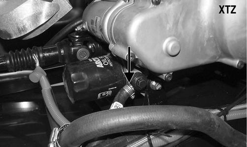
2.Using a suitable “T” fitting, connect Oil Pressure
Test Kit to the oil fitting and hose. Tighten all clamps securely. NOTE: Some oil seepage may occur when installing the
oil pressure gauge. Wipe up oil residue with a cloth.
3.Set the parking brake and start the engine. Allow the engine to warm up to operating temperature (with cooling fan cycling). 4.Set the speedometer/tachometer to RPM. With the engine running at 3000 RPM, the pressure gauge must show 1.05-1.2 kg/cm2 (15-17 psi). 5.Remove the test kit from the vehicle and install the oil hose. Tighten the clamps securely. 6.Install the seats, seat base, and center console as required making sure the seats lock securely. NOTE: If the oil pressure is lower than specified,
check for an oil leak, damaged oil seal, or defective oil pump.
NOTE: If the oil pressure is higher than specified,
check for too heavy engine oil weight (see the General Information section), clogged oil passage, clogged oil filter, or improper installation of the oil filter.
REMOVING/DISASSEMBLING 1.Remove the oil pump from the engine (see Left-Side
Components (XT/XTX) or Center Crankcase Components (XTZ) in the Engine/Transmission section). 2.Remove the Phillips-head screw on the back side of the pump and separate the pump housing and cover.
Note the position of the inner and outer rotors and alignment pin for assembly. 3.Remove oil pump components. CLEANING AND INSPECTING 1.Clean all oil-pump components. 2.Inspect the rotors for scoring and gouges. 3.Inspect the alignment pin, driveshaft, and driven sprocket for damage. 4.Inspect the pump housing and cover for cracks or damage. ASSEMBLING/INSTALLING 1.Place the rotors into the pump housing making sure the alignment pin is in the groove of the rotor. 2.Place the cover onto the pump housing. 3.Secure the pump with the Phillips-head screw coated with red Loctite #271. Tighten to 8 ft-lb. 4.Install the oil pump into the engine (see Left-Side
Components (XT/XTX) or Center Crankcase Components (XTZ) in the Engine/Transmission section).
Oil Cooler (XTZ)
This model has an oil cooler in addition to the liquid cooling system. An oil cooler kit may be installed on any Arctic Cat ROV.
REMOVING 1.Loosen the clamps securing the oil hoses to the oil cooler; then place a shallow pan or absorbent towel under the connection and remove the hoses.
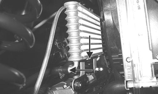
PR484A
2.Remove the flange nuts and cap screws from the oil cooler mountings and remove the oil cooler.
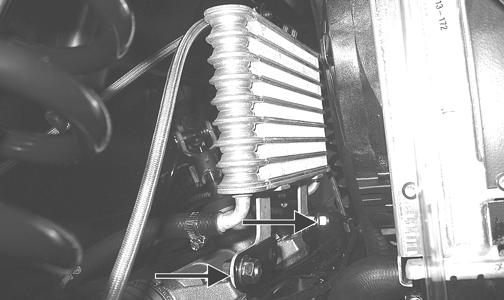
PR484B
CLEANING AND INSPECTING 1.Prior to washing, inspect the oil cooler for signs of leaks such as oily dirt build-up. 2.Wash the cooling fins using a garden hose and hot, soapy water and a soft brush. 3.Inspect all mounting brackets and the oil inlet and outlet for cracks or bends.
INSTALLING 1.Place the oil cooler into position and secure with the existing hardware. Tighten securely. 2.Connect the oil hoses and secure with the hose clamps. Tighten securely.
Liquid Cooling System
When filling the cooling system, use premixed Arctic Cat Antifreeze. While the cooling system is being filled, air pockets may develop; therefore, open the bleed screw on the upper coolant pipe or the thermostat housing to allow air to bleed from the cooling system. When clear coolant (no bubbles) is present, tighten the bleed screw securely; then fill the cooling system to the bottom of the stand pipe in the radiator neck. Run the engine for five minutes after the initial fill, shut the engine off, and then “top-off” the cooling system to the bottom of the stand pipe in the radiator neck.
CAUTION
After operating the vehicle for the initial 5-10 minutes, stop the engine, allow the engine to cool down, and check the coolant level. Add coolant as necessary.
Radiator
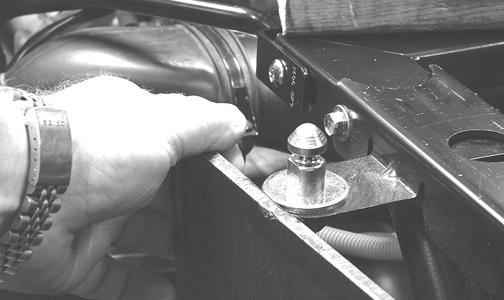
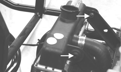
REMOVING 1.Remove the screws securing the dash assembly to the frame (two on each side, two front center, and three lower-rear dash). Slide the dash rearward approximately four inches. 2.Remove four torx-head screws (A) securing the under-hood storage box to the frame; then remove two cap screws with nuts (B) at the front of the storage box.
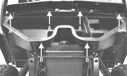
PR182A
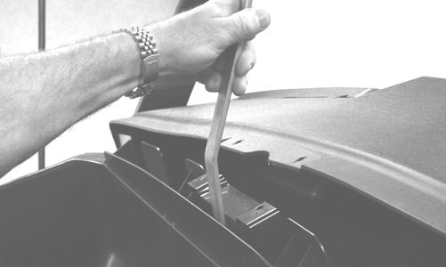
3.While lifting up on the front of the storage box, pry the rear center clear of the center dash mount and remove the storage box.
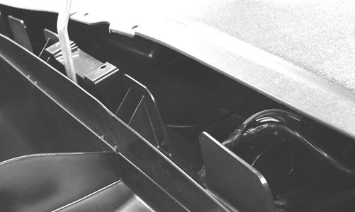
PR186
4.Drain the coolant into a suitable container; then disconnect the cooling fan wire connector from the main harness.
PR183A
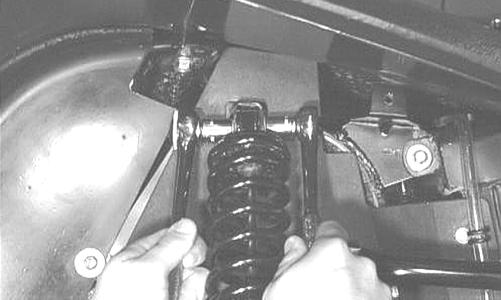
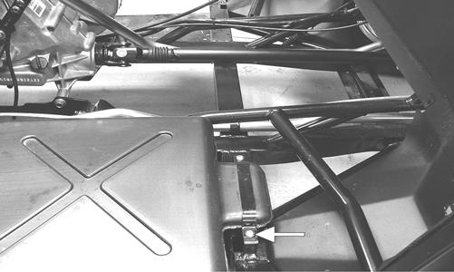
5.Remove the two shoulder bolts and nuts securing the radiator to the frame; then disconnect the upper and lower coolant hoses.
PR184A
6.Lift the radiator assembly from the vehicle. Account for two upper and two lower rubber mounting grommets.
CLEANING AND INSPECTING 1.Flush the radiator with water to remove any contaminants.
2.Inspect the radiator for leaks and damage. 3.Inspect all hoses for cracks and deterioration. 4.Inspect all fasteners and grommets for damage or wear.
INSTALLING 1.Place the radiator into position making sure the grommets are correctly installed; then secure to the mounts with the two shoulder bolts and nuts. Tighten securely.
PR184A
2.Connect the upper and lower coolant hoses to the radiator and secure with the appropriate hose clamps; then connect the cooling fan wire connector to the main harness.
PR183A
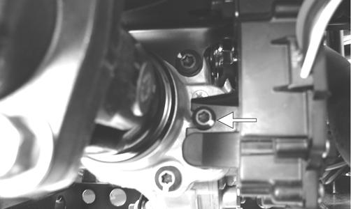
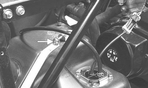
3.Open the high-point bleed screw on the upper coolant pipe to allow trapped air to escape. Tighten securely after filling. 4.Pour the recommended coolant into the radiator and secure the radiator cap. 5.Place the storage box into position and using a smooth, flat pry-bar, pry the center of the box past the dash mount; then secure with the appropriate fasteners. 6.Slide the dash forward into position; then secure the dash with the appropriate hardware. 7.Start the engine and warm up to operating temperature; then verify the coolant level is at the bottom of the stand pipe in the radiator neck. Add coolant as necessary.
Thermostat (XT/XTX)
REMOVING 1.Drain approximately one quart of coolant from the cooling system. 2.Remove the two cap screws securing the thermostat housing to the cylinder head. Account for a thermostat with seal.
INSPECTING 1.Inspect the thermostat for corrosion, wear, or spring damage. 2.Using the following procedure, inspect the thermostat for proper operation.
A.Suspend the thermostat in a container filled with water.
B.Heat the water and monitor the temperature with a thermometer.
C.The thermostat should start to open at 71.0-86.0° C (160-187° F).
D.If the thermostat does not open, it must be replaced. 3.Inspect all coolant hoses, connections, and clamps for deterioration, cracks, and wear. NOTE: All coolant hoses and clamps should be
replaced every four years or 4000 miles.
INSTALLING 1.Place the thermostat with seal into the thermostat housing; then secure the thermostat housing to the cylinder head with the two cap screws.
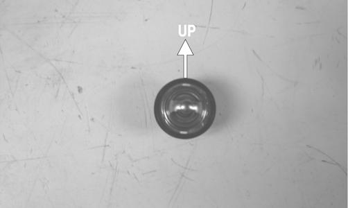
CAUTION
When installing the thermostat, make sure the bleed holes are straight up and down or air will remain trapped causing engine damage due to overheating.
PR281A
2.Fill the cooling system with the recommended amount of antifreeze. Check for leakage.
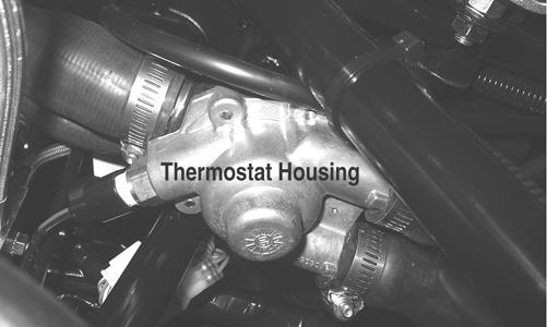
Thermostat (XTZ)
REMOVING
NOTE: The thermostat is located in a housing
in-line with the upper radiator hoses under the air filter housing.
GZ036A
1.Drain approximately one quart of coolant from the cooling system. 2.Remove the four machine screws securing the thermostat housing together. Remove the thermostat and account for an O-ring. INSPECTING 1.Inspect the thermostat for corrosion or spring damage. 2.Using the following procedure, inspect the thermostat for proper operation.
A.Suspend the thermostat in a container filled with water.
B.Heat the water and monitor the temperature with a thermometer.
C.The thermostat should start to open at 71.0-86.0°
C (160-187° F).
D.If the thermostat does not open, it must be replaced. 3.Inspect all coolant hoses, connections, and clamps for deterioration, cracks, and wear. NOTE: All coolant hoses and clamps should be
replaced every four years or 4000 miles.
INSTALLING 1.Place the thermostat and O-ring into the thermostat housing; then secure the thermostat housing together with the four machine screws.
2.Fill the cooling system with the recommended amount of antifreeze. Check for leakage.
Fan
REMOVING 1.Remove the radiator.
2.Remove the fan assembly from the radiator. INSTALLING 1.Position the fan assembly on the radiator; then secure with existing hardware. NOTE: The fan wiring must be in the upper-right
position.
2.Install the radiator.
Water Pump (XT/XTX)
NOTE: The water pump is not a serviceable compo-
nent. If the pump is defective or if the mechanical seal is leaking (coolant dripping from the discharge hole), the water pump must be replaced.
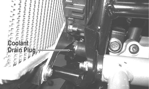
REMOVING 1.Remove the radiator cap; then remove the water pump coolant drain plug and drain the coolant.
NOTE: Always use a large container and have suffi-
cient floor drying material available when draining the coolant in case of coolant spillage.
2.Drain the oil from the engine/transmission. 3.Remove the seats and center console; then remove the right-side seat-base. 4.Loosen the coolant hose clamps and slide the clamps away from the hose ends.
PR132
5.Remove the two cap screws securing the water pump to the engine; then remove the water pump.
CC786A
INSTALLING 1.Secure the water pump to the engine with the two cap screws tightened securely.
CC786A
2.Connect the two coolant hoses to the water pump and secure with the clamps; then install the water pump coolant drain plug.
PR132
3.Fill the engine/transmission with the proper amount of recommended oil.
4.Fill the cooling system with the proper amount of recommended coolant.
NOTE: While the cooling system is being filled, air
pockets may develop; therefore, run the engine for five minutes after the initial fill, shut the engine off, and then fill the cooling system.
5.Check the entire cooling system for leakage.
6.Install the right-side seat-base; then install the center console and seats making sure the seats lock securely. CAUTION
After operating the vehicle for the initial 5-10 minutes, stop the engine, allow the engine to cool down, and check the coolant level. Add coolant as necessary.
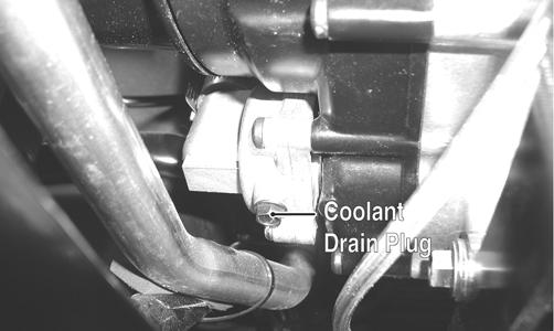
Water Pump (XTZ)
NOTE: The water pump is a non-serviceable compo-
nent. It must be replaced as an assembly.
REMOVING 1.Remove the coolant drain plug; then remove the radiator cap and drain the coolant into a suitable container.
GZ093A
NOTE: Always use a large container and have suffi-
cient floor drying material available when draining the coolant in case of coolant spillage.
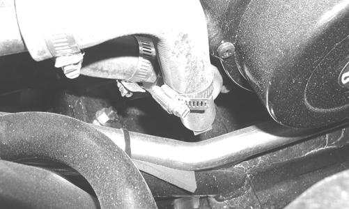
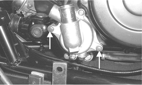
2.Remove the coolant hoses from the water pump; then remove two cap screws securing the water pump to the crankcase.
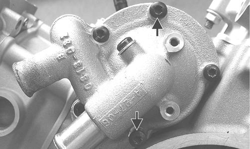
GZ230A
3.Remove the water pump from the engine. INSTALLING 1.Install a new O-ring onto the water pump and lightly coat with clean engine oil.
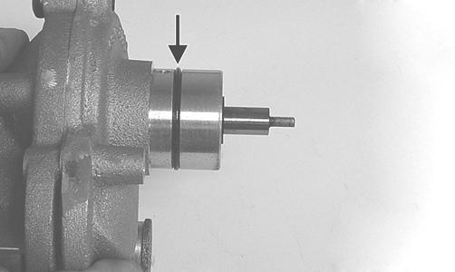
GZ252C
2.Install the water pump assembly onto the engine aligning the flat drive on the water pump to the slot in the driven gear shaft.
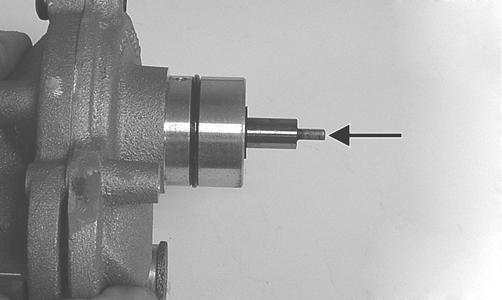
GZ252D
CAUTION
Do not force the water pump housing into the crankcase or sever engine damage may occur.
3.Secure the water pump with the two cap screws and tighten securely; then connect the coolant hoses and secure with hose clamps. 4.Tighten the coolant drain plug securely; then fill the cooling system with appropriate mixed coolant and install the radiator cap. 5.Start the engine and check for coolant leaks; then add coolant if necessary to proper level.
CAUTION
After operating the vehicle for the initial 5-10 minutes, stop the engine, allow the engine to cool down, and check the coolant level. Add coolant as necessary.
Electric Fuel Pump/Fuel Level Sensor
The electric fuel pump and fuel level sensor are not serviceable components. If either component fails, it must be replaced. TESTING
1.Turn the ignition switch ON and listen for a momentary “whirring” sound of the pump building pressure.
If the sound is heard (10 seconds), no electrical checks are necessary. Turn the ignition switch OFF. 2.Disconnect the gasline hose from the fuel rail; then install a suitable pressure gauge.
! WARNING
Whenever any maintenance or inspection is made on the fuel system during which there may be fuel leakage, there should be no welding, smoking, open flames, etc., in the area.
AT THIS POINT
Prior to removing the electric fuel pump, the following check should be performed to determine that removal is necessary.
! WARNING
Gasoline may be under pressure. Place an absorbent towel under the connector to absorb any gasoline spray when disconnecting.
3.Turn the ignition switch to the ON position. The fuel pressure should build until the pump shuts off. Pressure should read 3.0 kg-cm2 (43 psi). 4.If the pump is not running, disconnect the fuel pump/sensor connector by reaching under the rear rack from behind.
5.Connect a multimeter to the power supply leads with the red tester lead to the red wire and the black tester lead to the black wire; then turn the ignition switch to the ON position. The meter should read battery voltage. If battery voltage is indicated and the fuel pump does not run, replace the pump assembly. If no battery voltage is indicated, check the ECM and the vehicle tilt sensor.
REMOVING 1.Remove the key from the ignition switch.
2.Remove the seats, center console, and right-side seat-base; then disconnect the negative battery cable. 3.Disconnect the electrical plug from the main harness; then disconnect the gasline hose from the fuel pump. 4.Mark the fuel pump mounting and gas tank for installing purposes; then remove the screws securing the fuel pump to the gas tank and remove the fuel pump.
5.Using duct tape or other suitable means, cover the fuel pump opening. INSPECTING
1.Inspect the fuel screen and blow clean with low pressure compressed air. 2.Move the float lever and check for free movement.
The float assembly should return to the lower position without force. If not, replace the fuel level sensor assembly. 3.Test the fuel level sensor by connecting a multimeter (A) to the fuel level sensor leads (B); then select
OHMS. The multimeter should show 5 ohms at full fuel position (C) and 95 ohms at empty fuel position (D). ! WARNING
Always ensure that power cannot be inadvertently applied to the ignition/ECM when working on the fuel system. If the ignition switch is turned on, the electric fuel pump will start and gas could be rapidly pumped and spilled resulting in fire and severe injury.
CAUTION
Take care not to damage the float or float arm or replacement of the entire assembly will be necessary.
AT THIS POINT
If the pump has failed earlier test and must be replaced, proceed to INSTALLING.
ATV2116
NOTE: If readings are erratic, clean the resistor
wiper and resistor with clean alcohol and retest. If still not correct, replace the fuel level sensor.
4.To replace the fuel level sensor, use the following procedure.
A.Disconnect the two-wire connector (A); then press the fuel level sensor toward the top of the fuel pump to release it from the mounting slot (B).
FI460A
B.Engage the tabs (C) of the fuel level sensor into the mounting slot (B) and press toward the bottom of the fuel pump to latch in place; then connect the two-wire connector (A). INSTALLING 1.Place the fuel pump assembly into the gas tank with a new gasket aligning the match marks; then secure with the four screws. Tighten securely. NOTE: It is important to install the fuel pump with
the correct orientation to ensure adequate float lever clearance.
2.Connect the gasline hose to the fuel pump pipe and secure with the hose clamp; then connect the electrical plug to the main harness. 3.Connect the negative battery cable; then turn the ignition switch to the ON position and verify that no gas leaks are present, the pump runs for 2-3 seconds, and the gas gauge reading is normal. 4.Start the engine to verify proper engine operation; then shut off the engine and install the right-side seat-base, center console, and seats making sure the seats lock securely into place.
Troubleshooting
Problem: Starting impaired Condition Remedy
1. Gas contaminated 1.Drain gas tank and fill with clean gas
Problem: Idling or low speed impaired Condition Remedy
1. TPS out of adjustment 1.Adjust TPS
Problem: Medium or high speed impaired Condition Remedy
1. High RPM “cut out” against RPM limiter 1.Decrease RPM speed