9 minute read
Suspension

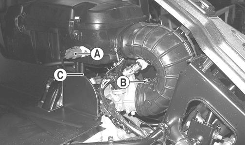
The following suspension system components should be inspected periodically to ensure proper operation.
A.Shock absorber rods bent, pitted, or damaged.
B.Rubber damper cracked, broken, or missing.
C.Shock absorber body damaged, punctured, or leaking.
D.Shock absorber eyelets broken, bent, or cracked.
E.Shock absorber eyelet bushings worn, deteriorated, cracked, or missing.
F.Shock absorber spring broken or sagging.
G.Sway bar mountings tight and bushings secure.
Shock Absorbers
REMOVING 1.Secure the vehicle on a support stand to elevate the wheels and to release load on the suspension.
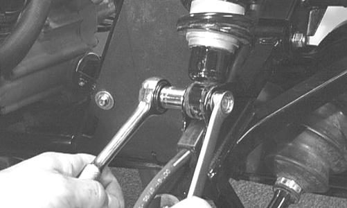
2.Remove the two cap screws and nuts securing each front shock absorber to the frame and upper A-arm.
Account for bushings and sleeves from each.
! WARNING
Make sure the vehicle is solidly supported on the support stand to avoid injury.
AF605D
CAUTION
Additional support stands are necessary to support the rear axle when the shock absorbers are removed or damage may occur.
3.Remove the two cap screws and nut securing each rear shock absorber to the frame and lower A-arm.
Account for bushings and sleeves from each.
AF626D
4.Using a suitable spring compression stand, compress the shock absorber spring, remove the retainer, and remove the spring.
! WARNING
Shock absorber springs are under high compression loads. Do not attempt to remove springs without an adequate spring compressor. Sever injury could result.
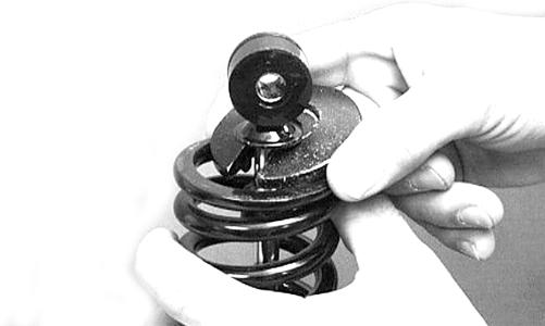
AF730D
CLEANING AND INSPECTING 1.Clean all shock absorber components in parts-cleaning solvent. 2.Inspect each shock rod for nicks, pits, rust, bends, and oily residue. 3.Inspect all springs, spring retainers, shock rods, sleeves, bushings, shock bodies, and eyelets for cracks, leaks, and bends. INSTALLING 1.Place the shock absorber spring over the shock absorber, compress the spring, and install the retainer. 2.Place bushings and sleeves (where appropriate) into shock eyelet; then install shocks with two cap screws and nuts. 3.On the XT/XTX, tighten the front shock absorber cap screws to 35 ft-lb and the rear shock absorber cap screws to 35 ft-lb (upper) or 20 ft-lb (lower). On the XTZ, tighten the front and rear shock absorber cap screws to 35 ft-lb. 4.Remove the vehicle from the support stand.
Front A-Arms
REMOVING 1.Secure the vehicle on a support stand to elevate the front wheels; then remove the wheels.
2.Remove the cotter pin from the nut. Discard the cotter pin. ! WARNING
Make sure the vehicle is solidly supported on the support stand to avoid injury.

PR257
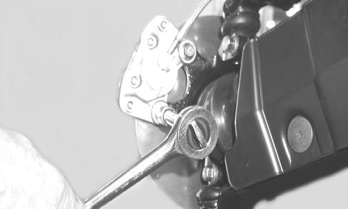
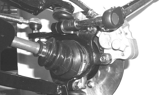
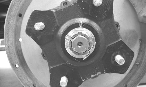
3.Remove the nut securing the hub. 4.Remove the brake caliper. Account for two cap screws.
CD007
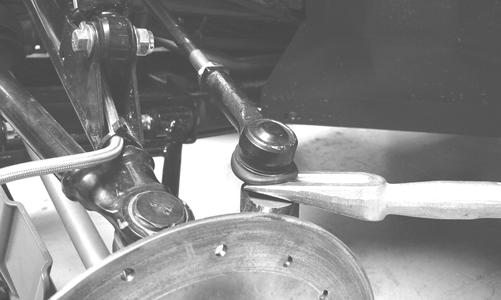
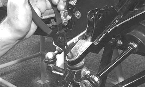
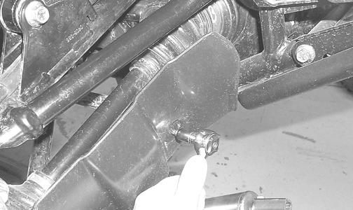
5.Remove the hub assembly. 6.Remove the cotter pin and slotted nut securing the tie rod end to the knuckle; then remove the tie rod end from the knuckle.
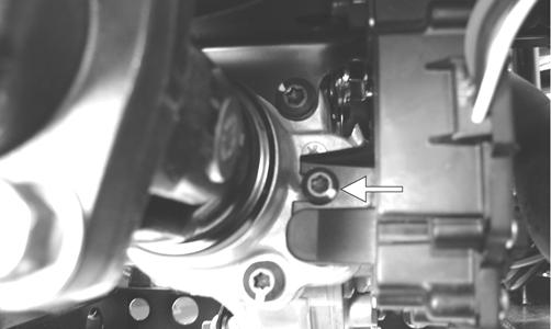
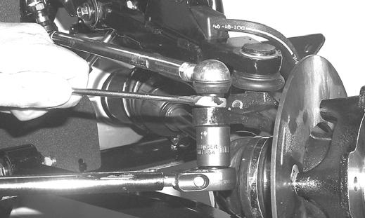
7.Remove the cap screws securing the ball joints to the knuckle.
CAUTION
Support the knuckle when removing the cap screws or damage to the threads will occur.

PR193
8.Tap the ball joints out of the knuckle; then remove the knuckle.
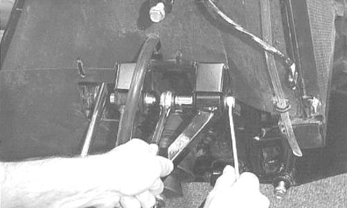
9.Remove the lower shock absorber eyelet from the upper A-arm.
AF626D
10.Remove the cap screws securing the A-arms to the frame.
AF610D
11.Remove the snap ring from the ball joint; then remove the ball joint from the A-arm.
AF616D
CLEANING AND INSPECTING 1.Clean all A-arm components in parts-cleaning solvent.
2.Clean the ball joint mounting hole of all residual
Loctite, grease, oil, or dirt for installing purposes. 3.Inspect the A-arm for bends, cracks, and worn bushings. 4.Inspect the ball joint mounting holes for cracks or damage. 5.Inspect the frame mounts for signs of damage, wear, or weldment damage. INSTALLING 1.Apply Loctite Primer “T” to the A-arm socket; then apply green Loctite #609 to the entire outside diameter of the ball joint. Install the ball joint into the
A-arm and secure with the snap ring.
AF616D
2.Install the A-arm assemblies into the frame mounts and secure with the cap screws. Only finger-tighten at this time.
AF610D
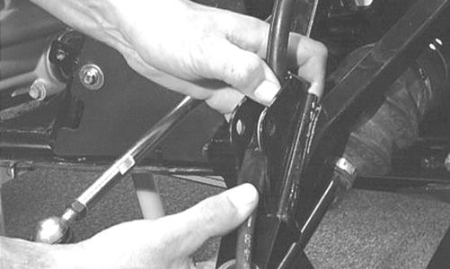
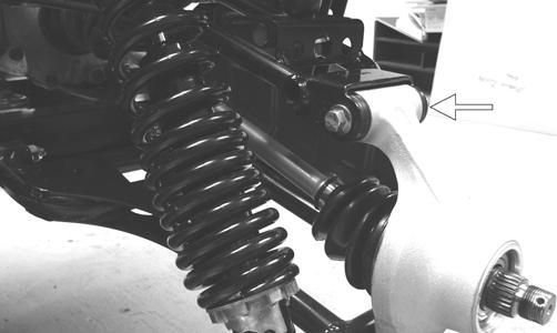
3.Route the brake hose through the upper A-arm shock absorber mount.
AF627D
4.Secure the lower eyelet of the shock absorber to the upper A-arm. Tighten nut to 35 ft-lb. 5.Secure the A-arm assemblies to the frame mounts (from step 2). Tighten the cap screws to 35 ft-lb. 6.Install the knuckle assembly onto the ball joints and secure with cap screws. Tighten to 35 ft-lb.
AF628D
7.Install the tie rod end and secure with the nut (coated with red Loctite #271). Tighten to 30 ft-lb; then install a new cotter pin and spread the pin to secure the nut.
NOTE: During assembly, new cotter pins should be
installed.
AF618D
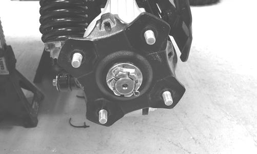
8.Apply grease to the hub and drive axle splines; then install the hub assembly onto the drive axle.
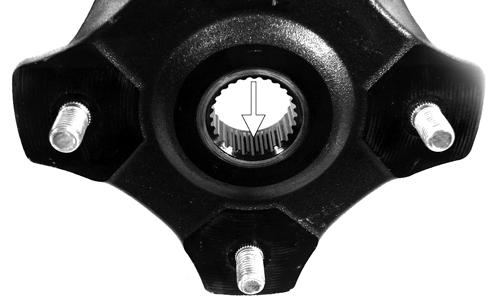
PR290A
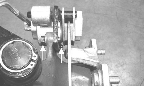
9.Secure the hub assembly with the nut. Tighten only until snug. 10.Secure the brake caliper to the knuckle with two new
“patch-lock” cap screws. Tighten to 20 ft-lb.
PR377B
11.Secure the hub nut (from step 9) to the shaft/axle.
Tighten to 200 ft-lb. 12.Install a new cotter pin and spread the pin to secure the nut.
NOTE: If the cotter pin cannot be inserted due to
misalignment of the hole in the axle and the slots in the nut, tighten the nut until properly aligned.
PR260
13.Install the wheel and tighten in a crisscross pattern in 20 ft-lb increments to 80 ft-lb (aluminum wheels) or 45 ft-lb (steel wheels). 14.Remove the vehicle from the support stand.
Rear A-Arms
REMOVING 1.Secure the vehicle on a support stand to elevate the wheels.
2.Set the parking brake. 3.Remove the wheel.
4.Remove the cotter pin securing the hex nut; then remove the hex nut.
5.Remove the cap screws and lock nut securing the shock absorber to the frame and lower A-arm; then remove the shock absorber.
6.Remove the cap screws securing the boot guard to the lower A-arm.
! WARNING
Make sure the vehicle is solidly supported on the support stand to avoid injury.
AF934
7.Slide the axle out of the knuckle and set aside.
8.Remove the cap screws and lock nuts securing the knuckle to the A-arms. Discard the lock nuts.
PR220A
NOTE: Never reuse a lock nut. Once a lock nut has
been removed, it must be replaced with a new lock nut.
9.Remove the cap screws and lock nuts securing the
A-arms to the frame; then remove the A-arms. CLEANING AND INSPECTING 1.Clean all A-arm components in parts-cleaning solvent.
2.Inspect the A-arm for bends, cracks, and worn bushings. 3.Inspect the frame mounts for signs of damage, wear, or weldment damage. INSTALLING 1.Install the A-arm assemblies into the frame mounts and secure with the cap screws and new lock nuts.
Finger-tighten only at this time. 2.Slide the knuckle onto the drive axle and into position on the A-arms; then secure the knuckle to the
A-arms with cap screws and new lock nuts. Tighten to 35 ft-lb.
3.Tighten the hardware securing the A-arms to the frame mounts (from step 1) to 35 ft-lb. 4.Apply grease on the drive axle splines; then install the hub assembly onto the drive axle.

PR221
5.Secure the hub assembly with the nut. Tighten to 200 ft-lb.
NOTE: If the cotter pin cannot be inserted due to
misalignment of the hole in the axle and the slots in the nut, tighten the nut until properly aligned.
PR196
7.Secure the shock absorber to the frame with a cap screw and new lock nut. Tighten to 33 ft-lb. 8.Secure the shock absorber to the lower A-arm with a cap screw and new lock nut. Tighten to 20 ft-lb. 9.Secure the boot guard to the lower A-arm with the two cap screws. Tighten securely. 10.Install the wheel and tighten in a crisscross pattern in 20 ft-lb increments to 80 ft-lb (aluminum wheels) or 45 ft-lb (steel wheels). 11.Remove the vehicle from the support stand.
Wheels and Tires
TIRE SIZE
! WARNING
Use only Arctic Cat approved tires when replacing tires. Failure to do so could result in unstable vehicle operation.
The ROV models are equipped with low-pressure tubeless tires of the size and type listed in the General Information section. Do not under any circumstances substitute tires of a different type or size.
! WARNING
Always use the size and type of tires specified. Always maintain proper tire inflation pressure.
! WARNING
Do not mix tire tread patterns. Use the same pattern type on front and rear. Failure to heed warning could cause poor handling qualities of the vehicle and could cause excessive drive train damage not covered by warranty.
TIRE INFLATION PRESSURE Front and rear tire inflation pressure should be 0.84-1.41 kg/cm2 (12-20 psi).
REMOVING 1.Secure the vehicle on a support stand to elevate the wheels.
2.Remove the nuts securing the wheels; then remove the wheels. ! WARNING
Make sure the vehicle is solidly supported on the support stand to avoid injury.
CLEANING AND INSPECTING 1.Clean the wheels and hubs with parts-cleaning solvent.
2.Clean the tires with soap and water. 3.Inspect each wheel for cracks, dents, or bends. 4.Inspect each tire for cuts, wear, missing lugs, and leaks. INSTALLING 1.Install each wheel on its hub and secure with the existing hardware. 2.Tighten in a crisscross pattern in 20 ft-lb increments to 80 ft-lb (aluminum wheels) or 45 ft-lb (steel wheels). CHECKING/INFLATING 1.Using an air pressure gauge, measure the air pressure in each tire. Adjust the air pressure as necessary to meet the recommended inflation pressure. 2.Inspect the tires for damage, wear, or punctures.
! WARNING
Do not operate the vehicle if tire damage exists.
NOTE: If repair is needed, follow the instructions
found on the tire repair kit or remove the wheel and have it repaired professionally.
NOTE: Be sure all tires are the specified size and
have identical tread pattern.
Troubleshooting
Problem: Suspension too soft Condition Remedy
1. Spring preload incorrect 1.Adjust preload 2. Spring(s) weak 2.Replace spring(s) 3. Shock absorber damaged 3.Replace shock absorber
Problem: Suspension too stiff Condition Remedy
1. Spring preload incorrect 1.Adjust preload 2. A-arm-related bushings worn 2.Replace bushing
Problem: Suspension noisy Condition Remedy
1. Cap screws (suspension system) loose 1.Tighten cap screws 2. A-arm-related bushings worn 2.Replace bushings
Problem: Vehicle pulling or steering erratic Condition Remedy
1. Vehicle steering is erratic on dry, level surface 1.Check front wheel alignment and adjust if necessary (see the Steering/Frame/Controls section) 2. Vehicle pulls left or right on dry, level surface 2.Check air pressure in tires and adjust to specifications
Printed in U.S.A. Trademarks of Arctic Cat Inc., Thief River Falls, MN 56701 p/n 2259-857