25 minute read
Periodic Maintenance

This section has been organized into sub-sections which show common maintenance procedures for the Arctic Cat ROV. SPECIAL TOOLS A number of special tools must be available to the technician when performing service procedures in this section. Refer to the current Special Tools Catalog for the appropriate tool description.
Description p/n
Compression Tester Kit 0444-213 Hub Retaining Wrench Oil Filter Wrench 0444-270 0644-389
Spanner Wrench Timing Light Valve Clearance Adjuster 0444-240 0644-296 0444-255
NOTE: Special tools are available from the Arctic
Cat Service Department.
Periodic Maintenance Chart
A = Adjust I = Inspect C = CleanL = Lubricate R = Replace T = Tighten
Battery Fuses
Item Initial Service After Break-In (First Month or 100 Miles) Every Day Every Month or Every 100 Miles
Every 3 Months or Every 300 Miles
Every 6 Months or Every 500 Miles Every Year or Every 1500 Miles
As Needed
I I C I R
Air Filter I I* R
Valve/Tappet Clearance Engine Compression Spark Plug(s)
Muffler/Spark Arrester
I I A I I I I R (4000 Mi or 18 Mo) C R Gas Hoses I I R (2 Yrs) Throttle Cable Ends/Accelerator Pedal Pivot I I C-L A-R Engine-Transmission Oil Level I A Engine-Transmission Oil/Filter R R*/R**/R*** R Front Differential - Rear Drive Lubricant I I R (4 Yrs) Tires/Air Pressure I I R Steering Components I I I R V-Belt I l R Suspension (Ball joint boots, drive axle boots I I R front and rear, tie rods, differential and rear drive bellows) Nuts/Bolts/Cap Screws T T A Ignition Timing I Headlight/Taillight-Brakelight I I R Switches I I R Shift Lever I A-L Gauges/Indicators I I R Frame/Welds I I l Electrical Connections l C Complete Brake System I I (Hydraulic & Parking) Brake Pads I I* R Brake Fluid I I R (2 Yrs) Brake Hoses I I R (4 Yrs) Coolant/Cooling System I I R (2 Yrs) Wheel Lug Nuts T T
* Service/Inspect more frequently when operating in adverse conditions. ** When using an API certified SM 0W-40 oil. *** When using Arctic Cat ACX All Weather synthetic oil, oil change and strainer inspection interval can be increased to every 1,000 miles or every year.
Lubrication Points
It is advisable to lubricate certain components periodically to ensure free movement. Apply light oil to the components using the following list as reference.
A.Accelerator Pedal Pivot/Cable Ends
B.Brake Pedal Pivot
C.Parking Brake Cable Ends D.Shift Cable
Air Filter
Use the following procedure to remove the filter and inspect and/or clean it. CLEANING AND INSPECTING FILTER
CAUTION
Failure to inspect the air filter frequently if the vehicle is used in dusty, wet, or muddy conditions can damage the engine.
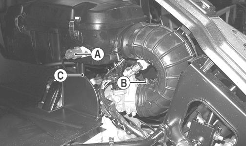
1.Remove the seats; then remove the center console. 2.Unsnap the four fasteners securing the air cleaner housing cover and remove the cover. 3.Remove the air filter frame (A); then remove the foam filter element (B).
PR576A
4.Fill a wash pan larger than the filter with a non-flammable cleaning solvent; then dip the filter in the solvent and wash it.
NOTE: Foam Filter Cleaner and Foam Filter Oil are
available from Arctic Cat.
5.Dry the filter. 6.Put the filter in a plastic bag; then pour in air filter oil and work the filter. Reattach the filter to the filter screen. CAUTION
A torn air filter can cause damage to the vehicle engine. Dirt and dust may get inside the engine if the element is torn. Carefully examine the element for tears before and after cleaning it. Replace the element with a new one if it is torn.
7.Clean any dirt or debris from inside the air cleaner.
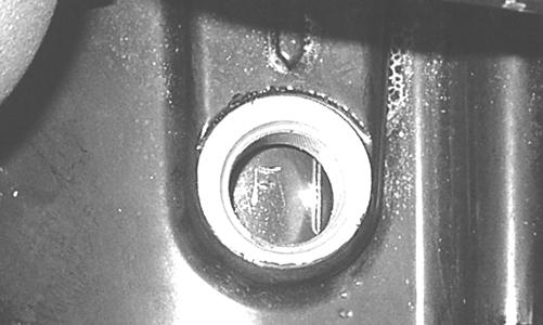
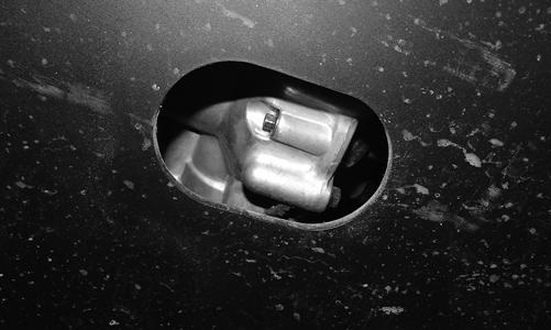
Be sure no dirt enters the throttle body. 8.Place the foam filter in the air filter housing; then position the filter frame on top. 9.Install the air filter housing cover and secure with the retaining clips; then install the center console and seats making sure the seats lock securely. CHECKING AND CLEANING DRAINS 1.Inspect one-way drains beneath the main housing for debris and for proper sealing. 2.Replace any one-way drain that is cracked or shows any signs of hardening or deterioration.
3.Wipe any accumulation of oil or gas from the filter housing and one-way drains.
CAUTION
The one-way drain to the left is the clean air section of the filter housing. Any leak of this drain will allow dirt into the engine intake causing severe engine damage.
Valve/Tappet Clearance
To check and adjust valve/tappet clearance, use the following procedure. NOTE: The engine must be cold for this procedure.
NOTE: The seats, center console, spark plug, and air filter housing must be removed for this procedure.
1.Remove the spark plugs and timing inspection plug; then remove the tappet covers (see the Engine/Transmission section - Servicing Top-Side Components). NOTE: On the XTZ, remove the crankshaft end cap
and install the special cap screw (left-hand threads) to rotate the engine.
2.Rotate the crankshaft to the TDC position on the compression stroke (front cylinder on the XTZ).
GZ063
NOTE: At this point, the rocker arms and adjuster
screws must not have pressure on them.
Feeler Gauge Procedure A.Using a feeler gauge, check each valve/tappet clearance. If clearance is not within specifications, loosen the jam nut and rotate the tappet adjuster screw until the clearance is within specifications. Tighten each jam nut securely after completing the adjustment.
CAUTION
The feeler gauge must be positioned at the same angle as the valve and valve adjuster for an accurate measurement of clearance. Failure to measure the valve clearance accurately could cause valve component damage. VALVE/TAPPET CLEARANCE
Intake 0.1016 mm (0.004 in.) Exhaust 0.1524 mm (0.006 in.)
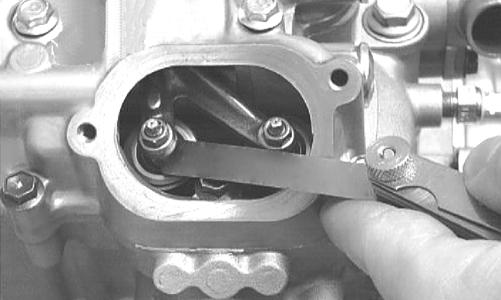
CC007DC
B.On the XTZ, rotate the engine 270° to the TDC position of the rear cylinder; then repeat step A. The stamped “R” must be visible.
GZ059
Valve Adjuster Procedure
A.Place the Valve Clearance Adjuster onto the jam nut securing the tappet adjuster screw; then rotate the valve adjuster dial clockwise until the end is seated in the tappet adjuster screw.
B.While holding the valve adjuster dial in place, use the valve adjuster handle and loosen the jam nut; then rotate the tappet adjuster screw clockwise until friction is felt.
C.Align the valve adjuster handle with one of the marks on the valve adjuster dial.
D.While holding the valve adjuster handle in place, rotate the valve adjuster dial counterclockwise until proper valve/tappet clearance is attained. NOTE: Refer to the appropriate specifications in
Feeler Gauge Procedure sub-section for the proper valve/tappet clearance.
NOTE: Rotating the valve adjuster dial counter-
clockwise will open the valve/tappet clearance by 0.05 mm (0.002 in.) per mark.
E.While holding the adjuster dial at the proper clearance setting, tighten the jam nut securely with the valve adjuster handle.
F.On the XTZ, rotate the engine 270° to the TDC position of the rear cylinder; then repeat steps A-E for the rear cylinder. 3.Install the spark plug(s) and timing inspection plug; then on the XTZ remove the cap screw and install the crankcase end cap. 4.Place the two tappet covers into position making sure the proper cap screws are with the proper cover.
Tighten the cap screws securely.
Testing Engine Compression
To test engine compression, use the following procedure.
NOTE: The engine should be warm (operating tem-
perature) and the battery fully charged for an accurate compression test. On the XT/XTX, throttle must be in the wide-open throttle (WOT) position. In the event the engine cannot be run, cold values are included.
NOTE: The seats and center console must be
removed for this procedure.
1.Remove the high tension lead from the spark plug(s). 2.Using compressed air, blow any debris from around the spark plug(s).
! WARNING
Always wear safety glasses when using compressed air.
3.Remove the spark plug(s); then attach the high tension lead(s) to the plug(s) and ground the plug(s) on the cylinder head(s) well away from the spark plug hole(s). 4.Attach the Compression Tester Kit. 5.While holding the throttle in the full-open position, crank the engine over with the electric starter until the gauge stops climbing (five to 10 compression strokes).
Model PSI Hot (WOT) PSI Cold (WOT)
XT 120-140 80-120 XTX 125-145 100-140 XTZ (Front) 125-145 80-120 XTZ (Rear) 165-185 150-190
6.If compression is abnormally low, verify the following items.
A.Starter cranks engine over.
B.Gauge is functioning properly.
C.Throttle in the full-open position.
D.Valve/tappet clearance correct.
E.Engine warmed up.
F.Intake not restricted.
NOTE: To service top-side components, see the
Engine/Transmission section.
7.Pour approximately 30 ml (1 fl oz) of oil into the spark plug hole(s), reattach the gauge, and retest compression. 8.If compression increases to normal, service the piston rings (see the appropriate Engine/Transmission -
Top side Components).
Spark Plug(s)
A light brown insulator indicates that the plug is correct. A white or dark insulator indicates that the engine may need to be serviced. To maintain a hot, strong spark, keep the plug free of carbon.
ATV-0051
CAUTION
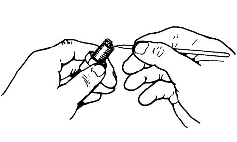
Before removing a spark plug, be sure to clean the area around the spark plug. Dirt could enter engine when removing or installing the spark plug.
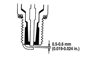
Adjust the gap to 0.5-0.6 mm (0.019-0.024 in.).
ATV0052E
When installing a spark plug, be sure to tighten it securely. A new spark plug should be tightened 1/2 turn once the washer contacts the cylinder head. A used spark plug should be tightened 1/8-1/4 turn once the washer contacts the cylinder head.
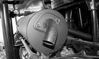
Muffler/Spark Arrester
Clean the spark arrester using the following procedure.
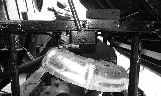
1.Remove the cap screws securing the spark arrester screen assembly to the muffler; then loosen and remove the spark arrester. Account for a gasket.
! WARNING
Wait until the muffler cools to avoid burns.
PR837
2.Using a suitable brush, clean the carbon deposits from the screen taking care not to damage the screen. NOTE: If the screen or gasket is damaged in any
way, it must be replaced.
3.Install the spark arrester assembly and gasket and secure with the cap screws. Tighten the cap screws to 48 in.-lb.
Engine/Transmission Oil - Filter
OIL - FILTER Change the engine oil and oil filter at the scheduled intervals. The engine should always be warm when the oil is changed so the oil will drain easily and completely. NOTE: To change oil and filter, the seats and center
console must be removed.
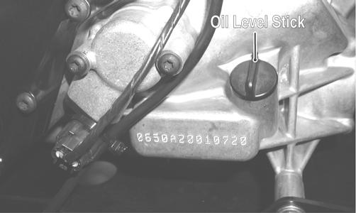
1.Park the vehicle on level ground. 2.Remove the oil level stick/filler plug.
PR053B GZ415A
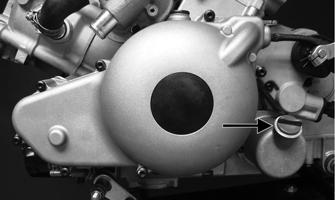
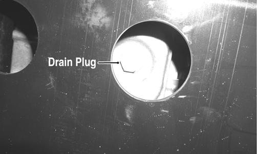
3.Remove the drain plug from the bottom of the engine and drain the oil into a drain pan.
PR078A
4.Using the Oil Filter Wrench and a ratchet handle (or a socket or box-end wrench), remove the old oil filter. NOTE: Clean up any excess oil after removing the filter.
5.Apply oil to a new filter O-ring and check to make sure it is positioned correctly; then install the new oil filter. Tighten securely. 6.Install the engine drain plug and tighten to 16 ft-lb.
Pour the specified amount of the recommended oil in the filler hole. Install the oil level stick/filler plug.
CAUTION
Any oil used in place of the recommended oil could cause serious engine damage. Do not use oils which contain graphite or molybdenum additives. These oils can adversely affect clutch operation. Also, not recommended are racing, vegetable, non-detergent, and castor-based oils.
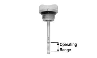
7.Start the engine (while the vehicle is outside on level ground) and allow it to idle for a few minutes. 8.Turn the engine off and wait approximately one minute. 9.Unscrew the oil level stick and wipe it with a clean cloth. 10.Install the oil level stick and thread into the engine case. NOTE: The oil level stick should be threaded into
the case for checking the oil level.
11.Remove the oil level stick; the oil level must be within the operating range but not exceeding the upper mark.
GZ461A
CAUTION
Do not over-fill the engine with oil. Always make sure that the oil level is not above the upper mark.
12.Inspect the area around the drain plug and oil filter for leaks.
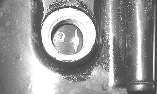
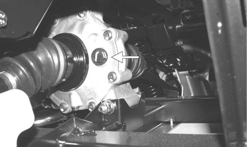
Front Differential - Rear Drive Lubricant
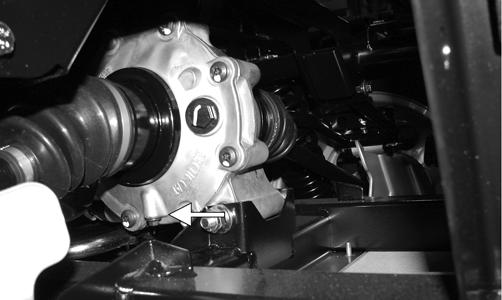
To check lubricant, use the following procedure. 1. Remove the fill plug; the lubricant level should be one inch below the plug threads.
PR530A
2.If low, add SAE approved 80W-90 hypoid gear lube as necessary. To change the lubricant, use the following procedure. 1.Place the vehicle on level ground. 2.Remove each fill plug. 3.Drain the lubricant into a drain pan by removing in turn the drain plug from each.
HDX255
Rear Drive
PR530B
4.After all the lubricant has been drained, install the drain plugs and tighten to 45 in.-lb. 5.Pour the appropriate amount of recommended lubricant into the fill hole.
6.Install the fill plug. NOTE: If the lubricant is contaminated with water,
inspect the drain plug, fill plug, and/or bladder.
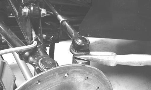
Driveshaft/Coupling
The following drive system components should be inspected periodically to ensure proper operation.
A.Spline lateral movement (slop).
B.Coupling cracked, damaged, or worn.
C.Universal joints worn or missing bearings.
Nuts/Bolts/Cap Screws
Tighten all nuts, bolts, and cap screws. Make sure rivets holding components together are tight. Replace all loose rivets. Care must be taken that all calibrated nuts, bolts, and cap screws are tightened to specifications.
Headlight/Taillight-Brakelight
HEADLIGHT
NOTE: The bulb portion of the headlight is fragile.
HANDLE WITH CARE. When replacing the headlight bulb, do not touch the glass portion of the bulb. If the glass is touched, it must be cleaned with a dry cloth before installing. Skin oil residue on the bulb will shorten the life of the bulb.
! WARNING
Do not attempt to remove the bulb when it is hot. Severe burns may result.
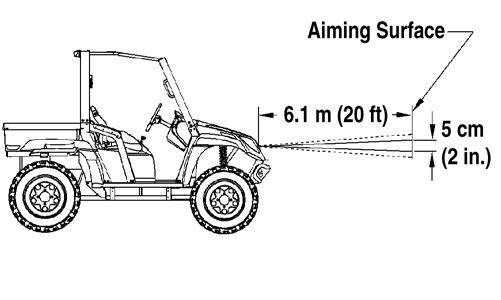
To replace the headlight bulb, use the following procedure. 1.Remove the wiring harness connector from the back of the headlight. 2.Grasp the bulb socket, turn it counterclockwise and remove, and pull the bulb straight out of the socket. 3.Install the new bulb into the socket and rotate it completely clockwise in the housing. 4.Install the wiring harness connector. TAILLIGHT-BRAKELIGHT To replace the taillight-brakelight bulb, use the following procedure. 1.Remove the two machine screws and remove the light assembly. 2.Rotate the bulb socket counterclockwise to remove it from the light assembly; then pull straight out on the bulb. Push the new bulb straight into the socket. 3.Install the bulb and socket into the light assembly and turn clockwise to lock in place. 4.Install the taillight-brakelight assembly on the canopy support. CHECKING/ADJUSTING HEADLIGHT AIM The headlights can be adjusted vertically. The geometric center of the HIGH beam light zone is to be used for vertical aiming. 1.Position the vehicle on a level floor so the headlights are approximately 6.1 m (20 ft) from an aiming surface (wall or similar aiming surface). NOTE: There should be an average operating load
on the vehicle when adjusting the headlight aim.
2.Measure the distance from the floor to the mid-point of each headlight. 3.Using the measurements obtained in step 2, make horizontal marks on the aiming surface. 4.Make vertical marks which intersect the horizontal marks on the aiming surface directly in front of the headlights. 5.Switch on the lights. Make sure the HIGH beam is on. DO NOT USE LOW BEAM.
6.Observe each headlight beam aim. Proper aim is when the most intense beam is centered on the vertical mark 5 cm (2 in.) below the horizontal mark on the aiming surface.
0740-647
7.Using the adjuster knob, adjust each headlight until correct aim is obtained.
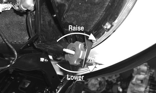
CD714A
Shift Lever (XT/XTZ)
CHECKING SHIFT CABLE Set the parking brake and turn the ignition switch on; then with the shift lever in the neutral position, look for the (N) indication on the LCD. Shift into high range and look for the (H) indication, low range for the (L) indication, and reverse for the (R) indication. Shift the transmission into neutral and turn the ignition switch off.
PR571
ADJUSTING SHIFT CABLE To adjust the shift cable, use the following procedure. 1.Set the parking brake; then remove the seats and center console.
2.Make sure the shift lever is in neutral; then remove the E-clip securing the cable end to the shaft arm.
PR567A
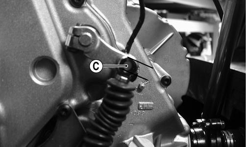
3.Loosen nuts (A) and (B) and adjust the cable housing to align the shift cable end to the shift arm stud (C).
PR568A PR572A
4.Install the E-clip; then tighten the nuts (A) and (B) securely. 5.Check each gear shift position for proper gear selection and make sure the proper icon illuminates on the
LCD; then install the center console and seats.
Shift Lever/Shift Cable (XTX)
CHECKING
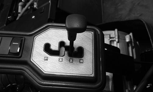
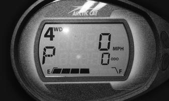
Turn the ignition switch on; then shift the transmission into park. The letter P should illuminate on the LCD gauge and the park icon (P) should illuminate. The vehicle should not be able to move.
HDX203
Move the shift lever all the way to the rear. The letter L should illuminate on the LCD gauge.
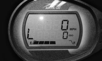
If either park or low range cannot be reached, the shift cable must be adjusted. ADJUSTING NOTE: Shift cable adjustment should not be neces-
sary unless replacing the shift cable or shift lever.
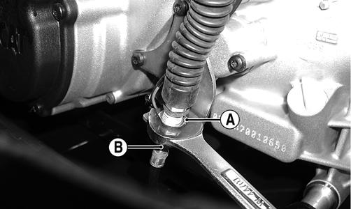
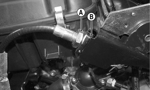
1.Remove the seats; then remove the battery cover and center console. 2.Loosen adjuster nut (A) and jam nut (B) and adjust the cable as necessary to obtain park in the full aft position of the shift lever and low range full forward.
Tighten the jam nut securely.
HDX251A
Hydraulic Brake System
NOTE: The XT/XTX models are equipped with drive-
line hydraulic and cable-actuated calipers incorporating a bleed screw for the hydraulic brake and a cable adjuster for parking brake adjustment. The XTZ model is equipped with hydraulic brakes at all four wheels and a cable only actuated driveline parking brake.
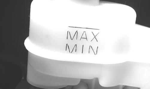
CHECKING/BLEEDING The hydraulic brake system has been filled and bled at the factory. To check and/or bleed a hydraulic brake system, use the following procedure. 1.With the master cylinder in a level position, check the fluid level in the reservoir. If the level in the reservoir is not above the MIN, add DOT 4 brake fluid. 2.Depress the brake pedal several times to check for a firm brake. If the brake is not firm, the system must be bled.
3.To bleed the brake system, use the following procedure.
A.Remove the cover and fill the reservoir with DOT 4 Brake Fluid.
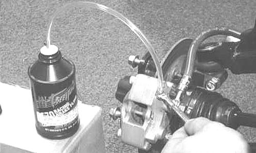
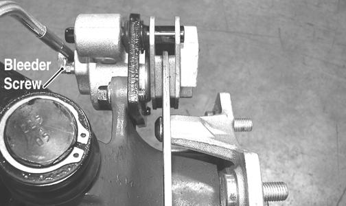
B.Install and secure the cover; then slowly depress the brake pedal several times. C.Remove the protective cap, install one end of a clear hose onto the REAR bleeder screw, and direct the other end into a container; then while holding slight pressure on the brake pedal, open the bleeder screw and watch for air bubbles. Close the bleeder screw before releasing the brake pedal. Repeat this procedure until no air bubbles are present.
AF637D
PR377C
NOTE: During the bleeding procedure, watch the
reservoir very closely to make sure there is always a sufficient amount of brake fluid. When the level falls below MIN, refill the reservoir before the bleeding procedure is continued. Failure to maintain a sufficient amount of fluid in the reservoir will result in air in the system.
D.At this point, perform steps B and C on the
FRONT RIGHT bleeder screw; then move to the
FRONT LEFT bleeder screw(s) and follow the same procedure. E.Repeat steps B and C until the brake pedal is firm.
4.Carefully check the entire hydraulic brake system that all hose connections are tight, the bleed screws are tight, the protective caps are installed, and no leakage is present.
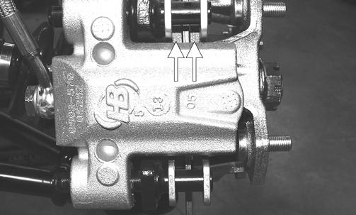
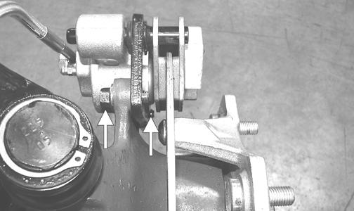
INSPECTING HOSES Carefully inspect the hydraulic brake hoses for cracks or other damage. If found, the brake hoses must be replaced. CHECKING/REPLACING PADS The clearance between the brake pads and brake discs is adjusted automatically as the brake pads wear. The only maintenance that is required is replacement of the brake pads when they show excessive wear. Check the thickness of each of the brake pads as follows. 1.Remove a front wheel.
2.Measure the thickness of each brake pad.
CAUTION
This hydraulic brake system is designed to use DOT 4 brake fluid only. If brake fluid must be added, care must be taken as brake fluid is very corrosive to painted surfaces.
PR376A
3.If thickness of either brake pad is less than 1.0 mm (0.039 in.), the brake pads must be replaced. NOTE: The brake pads should be replaced as a set.
4.To replace the brake pads, use the following procedure.
A.Remove the wheel.
B.Remove the cap screws securing the caliper holder to the knuckle; then remove the pads from the caliper. C.Install the new brake pads. D.Secure the caliper holder to the knuckle with new
“patch-lock” cap screws. Tighten to 20 ft-lb.
PR377B
E.Install the wheel. Tighten in a crisscross pattern in 20 ft-lb increments to 80 ft-lb (aluminum wheels) or 45 ft-lb (steel wheels). 5.Burnish the brake pads (see Burnishing Brake Pads in this section). BRAKE DISC Using a micrometer, measure the thickness of the brake disc in the contact surface. If thickness is 0.125-in. or less, the disc must be replaced. To replace the brake disc, see the Drive System section – Hub.
Parking Brake (XT/XTZ)
CHECKING Although the parking brake has been adjusted at the factory, the brake should be checked for proper operation. The brake must be maintained to be fully functional. 1.With the engine off, transmission in neutral, and the parking brake set, attempt to move the vehicle. 2.If the rear wheels are locked, it is adjusted properly. 3.If the rear wheels are not locked, it must be adjusted (set up). ADJUSTING 1.Remove the seats and center console.
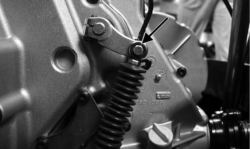
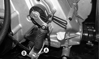
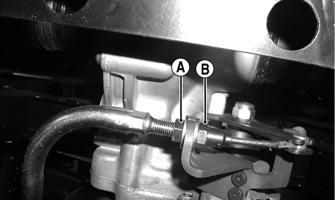
2.With the parking brake lever released, loosen the adjuster nut (A); then turn the jam nut (B) clockwise several turns.
PR682A
3.Turn the adjuster nut clockwise to remove cable slack. 4.Check for proper adjustment by applying the parking brake and attempting to move the vehicle. The vehicle should not move.
5.If adjustment is correct, tighten the adjuster nut securely. On the XTZ if further adjustment is required, repeat steps 2-4. On the XT, proceed to step 6. 6.Release parking brake lever to fully-off position; then loosen the nut (B) and turn nut (A) clockwise several turns.
PR097B
7.Check for proper adjustment by applying the parking brake and attempting to move the vehicle. The vehicle should not move.
8.If adjustment is correct, tighten the nut (B) securely. NOTE: If the parking brake cannot be “set-up” suffi-
ciently to hold the rear axle, new brake pads must be installed (proceed to appropriate Replacing Brake Pads in this sub-section).
CAUTION
If after adjusting the parking brake cable the parking brake will not hold the vehicle, the brake pads must be replaced.
MEASURING/REPLACING BRAKE PADS (XT) Removing 1.Remove the parking brake cable. 2.Lift the cargo box; then disconnect the lower lift support and allow the cargo box to tilt all the way back.
Account for the washer.
UTV355
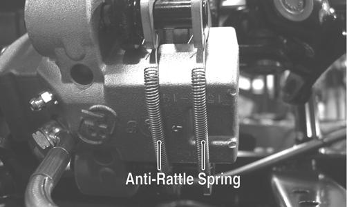
3.Remove the two cap screws securing the brake caliper to the rear drive housing and remove the caliper. 4.Remove the anti-rattle springs; then push in on the caliper holder and remove the outer brake pad.
Remove the inner pad.
PR466A
Inspecting and Measuring 1.Inspect the pads for gouges, chips, or wear. 2.Inspect the disc for gouges, grooves, cracks, and warpage. 3.Using a calipers, measure the thickness of each brake pad. 4.If the thickness of either brake pad is less than 1.0 mm (0.039 in.), the brake pads must be replaced. NOTE: The brake pads should be replaced as a set.
Installing 1.Place the brake pads into the caliper holder; then install the anti-rattle springs. NOTE: The metal backing of the pad will be facing
the actuator when installed properly.
2.Slide brake caliper assembly over the brake disc and into position on the rear drive housing; then secure the caliper with new “patch-lock” cap screws tightened to 20 ft-lb.
3.Install and adjust the parking brake cable (see
Adjusting in this sub-section). 4.Connect the lift support to the cargo box.
NOTE: Whenever installing new pads, the new pads
must be burnished (see Burnishing Brake Pads in this section).
MEASURING/REPLACING BRAKE PADS (XTZ)
NOTE: The brake pads should be replaced as a set.
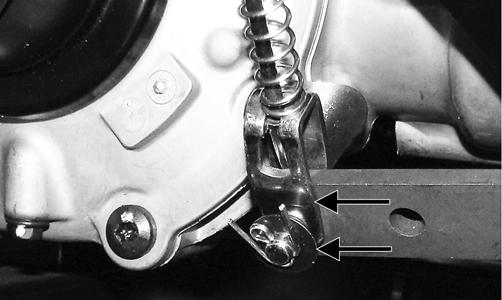
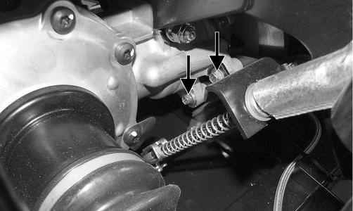
1.Disconnect the parking brake cable from the actuator arm. Account for a flat washer.
PR681A
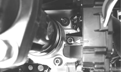
2.Remove the two cap screws and nuts securing the cable support to the brake caliper.
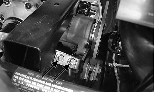
PR677A
3.Remove the two cap screws securing the brake caliper to the gear case housing; then remove the caliper assembly from the vehicle.
PR683A
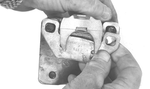
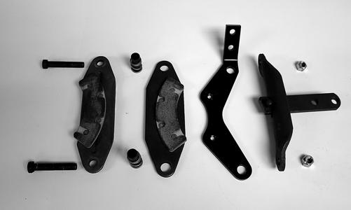
4.Remove the two lock nuts (A) from the brake pad anchor bolts; then remove the brake pads (B).
Account for two springs and spacers (C).
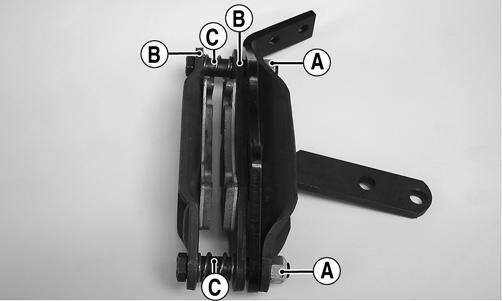
PR678A
5.Install the new brake pads and anchor bolts with springs and spacers; then secure with new lock nuts.
PR679
6.Install the brake caliper onto the gear case housing mounting bracket; then secure with two new
“patch-lock” cap screws and tighten to 20 ft-lb.
PR683A
7.Install the cap screws securing the cable support to the caliper and tighten securely.
8.Connect the brake cable to the actuator arm with the pin and flat washer and secure with the cotter pin; then adjust the parking brake.
PR681A
NOTE: Whenever installing new pads, the new pads
must be burnished (see Burnishing Brake Pads in this section).
Burnishing Brake Pads
Brake pads must be burnished to achieve full braking effectiveness. Braking distance will be extended until brake pads are properly burnished. To properly burnish the brake pads, use the following procedure.
1.Choose an area large enough to safely accelerate the vehicle to 30 mph and to brake to a stop. 2.Accelerate to 30 mph; then depress the brake pedal to decelerate to 0-5 mph. 3.Repeat procedure 20 times until brake pads are burnished.
4.Adjust the parking brake (if necessary). 5.Verify that the park indicator light illuminates when the parking brake is set (ignition switch on).
! WARNING
Failure to properly burnish the brake pads could lead to premature brake pad wear or brake loss. Brake loss can result in severe injury.
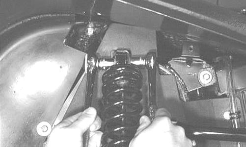
Checking/Replacing V-Belt
REMOVING 1.Remove the seats and center console; then remove the left-side seat-base (XT/XTX) or right-side seat base (XTZ). 2.Remove the floor; then on the XT/XTX, loosen the gas tank and slide it forward. 3.Remove the cap screws securing the V-belt cover noting the location of the different-lengthed cap screws for installing purposes; then using a rubber mallet, gently tap on the cover tabs to loosen the cover. Remove the cover.
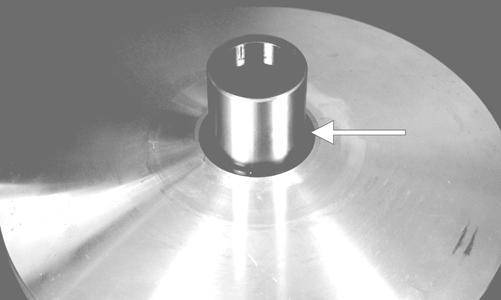
4.Remove the nut securing the movable drive face; then remove the face. Account for the flat washer and spacer. NOTE: Keep the drive face plate in contact with the
drive face when removing or installing the drive face to prevent the rollers from falling out.
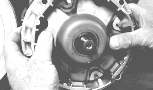
CD963
CD966A
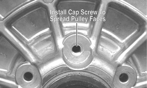
5.Install one of the V-belt cover cap screws into the driven pulley fixed face; then turn the cap screw clockwise to spread the pulley faces. Remove the
V-belt.
PR476A
GZ085
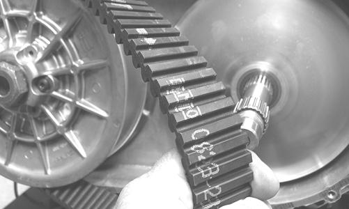
INSTALLING 1.Place the V-belt into position on the driven pulley and over the front shaft.
GZ085
NOTE: The arrows on the V-belt should point in the
direction of engine rotation.
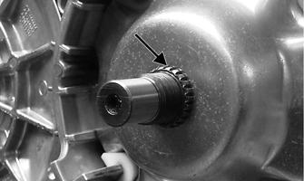
2.Pinch the V-belt together near its center and slide the spacer and movable drive face onto the driveshaft.
Secure the drive face with a washer and nut (coated with red Loctite #271). Using Spanner Wrench, tighten the nut to 165 ft-lb.
CAUTION
Make sure the movable drive face plate is fully engaged onto the splines of the clutch shaft before tightening the nut or false torque readings may occur. This will cause the assembly to loosen damaging the shaft and clutch face plate.
GZ485A
NOTE: At this point, remove the cap screw from the
driven pulley face.
3.With the vehicle in neutral, rotate the V-belt and driven pulley/clutch counterclockwise until the
V-belt is flush with the top of the driven pulley. 4.Place the V-belt cover gasket into position; then install the cover and secure with the cap screws making sure the different-lengthed cap screws are in their proper location. Tighten the cap screws to 8 ft-lb. 5.Secure the seat-base with the four cap screws.
Tighten securely. 6.Slide the gas tank into position (XT/XTX) and secure with the cap screws; then install the floor. 7.Install the seats and center console making sure the seats lock securely in place.