s. in fo
MAINTENANCE
SERIES
ch l
es
General Editor BERNAL OSBORNE of Motor Cycling
First published 1958
m
SINGLE-CYLINDER 347 c.c. and 498 c.c. and EX-W.D. 347 c.c. MODELS
at
MATCHLESS MOTORCYCLES 1939-55
aj
s-
©TEMPLE PRESS LIMITED, 1958
w.
TEMPLE PRESS LIMITED
ww
BOWLING GREEN LANE, LONDON, E.C.1
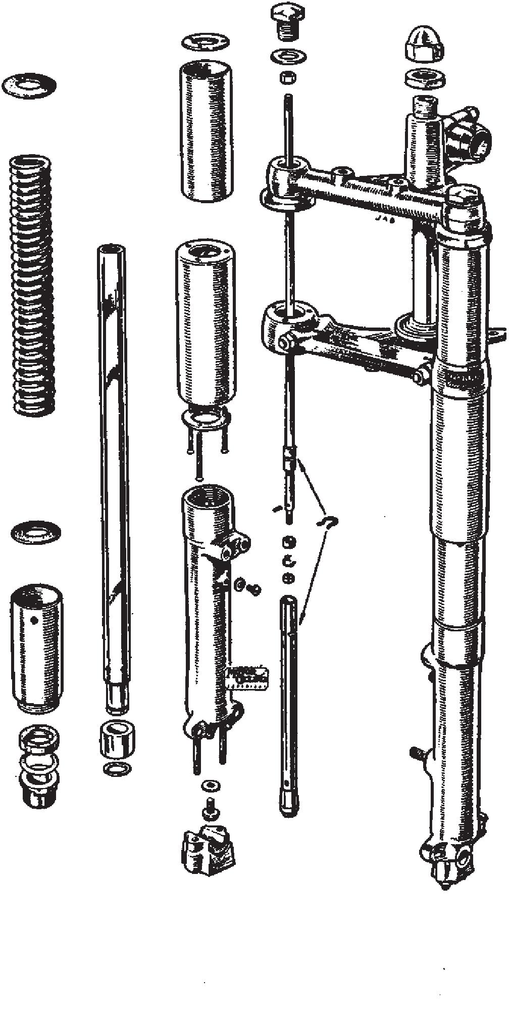
MATCHLESS SINGLES 1939 -1955
A maker's definitive photograph by courtesy of Motorcycle Sport for the 1953 500 cc Matchless. G80C shown here in trials guise with light-alloy motor, pre-Monobloc carburetter, rigid frame, Burman box and the AJS-style of forward mounted magneto introduced from September 1951. The Lucas instrument here is of course the Wader type. It has the new-type front brake brought in September 1952, the fullwidth front hub not arriving until 12 months later