8750 WALKING DRAGLINE
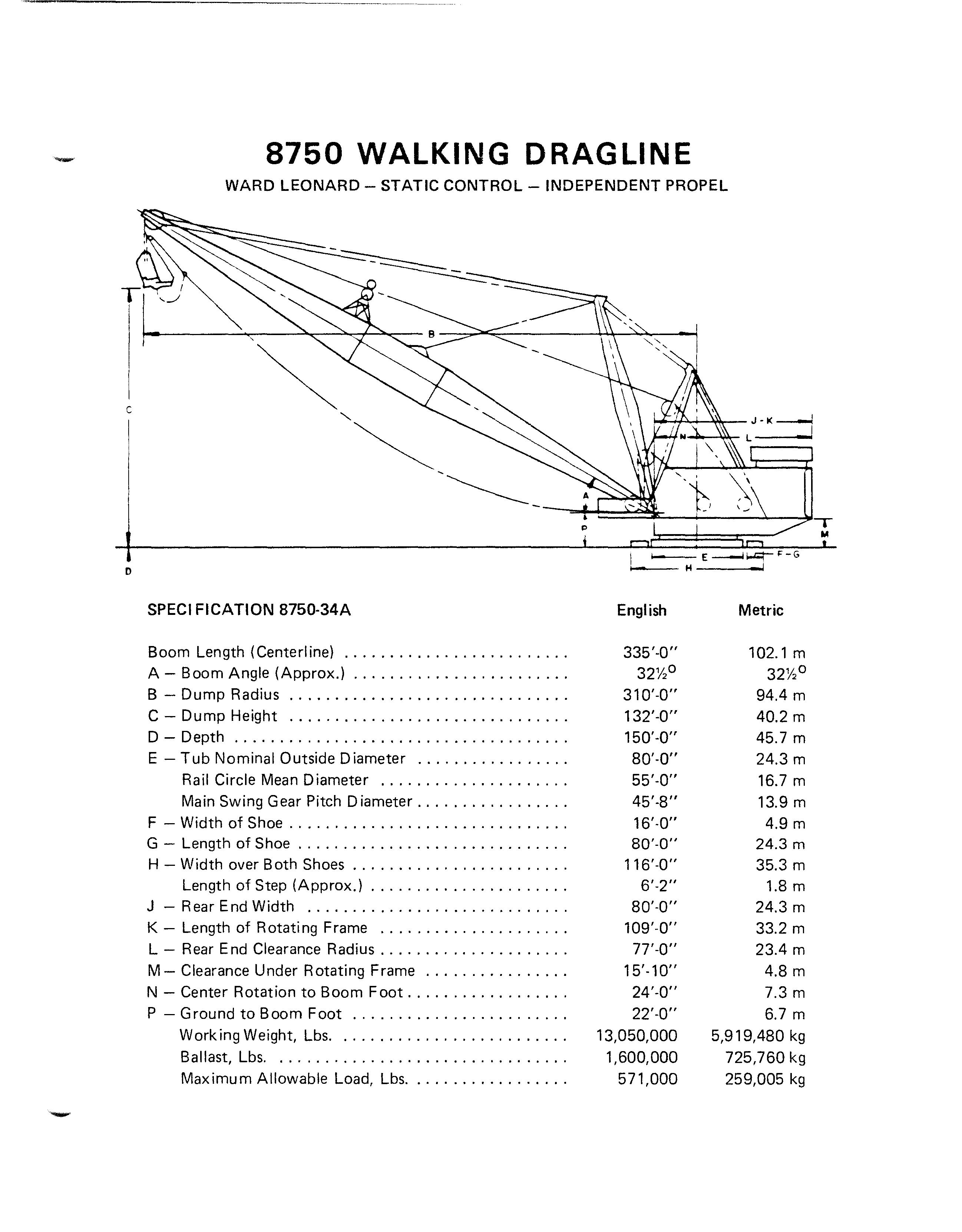
WARD LEONARD - STATIC CONTROL - INDEPENDENT PROPEL
SPECI FICATION 8750-34A
Boom Length (Centerl ine)
A- Boom Angle (Approx.) ,
B- Dump Radius
C- Dump Height .
0- Depth , ,
E- Tub Nominal Outside Diameter
Rail Circle Mean Diameter .
Main Swing Gear Pitch Diameter
F- Width of Shoe
G- Length of Shoe .
H- Width over Both Shoes
Length of Step (Approx.) .
J- Rear End Width
K- Length of Rotating Frame .
L- Rear End Clearance Radius
M- Clearance Under Rotating Frame .
N- Center Rotation to Boom Foot
P- Ground to Boom Foot
Working Weight, Lbs
Ballast, Lbs.
Maximum Allowable Load, Lbs ,
o
T M H I English Metric 335'·0" 102.1 m 32%0 32%0 310'-0" 94.4 m 132'-0" 40.2 m 150'-0" 45.7 m 80'·0" 24.3 m 55'-0" 16.7 m 45'·8" 13.9 m 16'·0" 4.9 m 80'-0" 24.3 m 116'-0" 35.3 m 6'-2" 1.8 m 80' -0" 24.3 m 109'-0" 33.2 m 77' -0" 23.4 m 15'·10" 4.8 m 24'·0" 7.3 m 22'·0" 6.7 m 13,050,000 5,919,480 kg 1,600,000 725,760 kg 571,000 259,005 kg BI006265
PRINCIPAL WEIGHTS

PROPEL MACHINERY WEIGHTS: Motor Extension Shaft
1st I ntermediate Shaft
2nd I ntermediate Shaft
Propel Brake
Propel Brake Guard
1st I ntermed iate Gear
2nd Intermediate Gear
Propel Motor Coupling
Propel Shaft Propel Gear
ROTATING MACHINERY WEIGHTS:
Main
Walking Arm Walking Eccentric Eccentric Bearing Housings
Gear Bearing Housings Eccentric Split Collar Stabilizer Arm Link Pin Lateral Ball Joint Shaft Walking Shoe Knuckle Walking Shoe Spherical Bushing Walking Shoe Shaft Bushing Walking Shoe
Propel Gear Hub Propel
Motor Base Case Cover Main Rotating Gear I ntermediate Gear Motor Extension Shaft I ntermediate Shaft Case Structure Main Rotating Shaft Main Shaft Pinion Main Shaft Sleeve Main Shaft Bearing ( Ibs.) 1,365 6,271 27,438 2,130 320 3,504 10,263 375 39,700 53,066 106,772 48,039 17,730 15,700 4,750 3,683 12,294 20,224 8,986 7,889 3,819 433 329,368 5,224 13,154 18,500 5,546 534 3,520 16,520 23,400 5,000 2,751 985 (kg) 619 2,845 12,446 966 145 1,589 4,655 170 18,008 24,071 48,409 21,790 8,042 7,122 2,155 1,671 5,577 9,174 4,076 3,578 1,732 196 149,401 2,370 5,967 8,392 2,516 242 1,597 7,493 10,614 2,268 1,248 447 BI006265
Principal Weights (cant.)
-........
HOIST/DRAG DRUM WEIGHTS:
Lagging (Each Section)
Drum End
Split Drive Gear
Bearing
Bearing Housing
HOIST/DRAG GEAR CASE WEIGHTS:
Motor Extension Shaft (Hoist)
Motor Extension Shaft (Drag) Case Cover (Hoist) Case Cover (Drag)
Intermediate Shaft Assembly
BOOM POINT SHEAVE ASSEMBLY WEIGHTS:
FAIR LEAD ASSEMBLY WEIGHTS:

Point Shaft Sheave (Each) Bearing (Each) Total Weight
Upper Sheave Lower Sheave Swivel Frame Upper Swivel Shaft Lower Swivel Shaft (Ibs.) 68,490 26,918 28,068 985 5,171 1,610 1,420 3,900 3,140 23,254 10,458 3,690 208 32,000 22,273 22,480 17,600 2,158 2,559 (kg) 31,067 12,210 12,732 447 2,346 730 644 1,769 1,424 10,548 4,744 1,674 94 14,515 10,103 10,197 7,983 979 1,161 BI006265

BI006265
This manual is divided into sections covering various serviceable components and systems of the Model 8750 dragline. These sections are organized by thumb index tabs shown below and right-black ink tab marks.

SECTION 1- INTRODUCTION
SECTION 2- OPERATION
SECTION 3- LUBRICATION
SECTION 4- MECHANICAL ADJUSTMENTS
SECTION 5- ELECTRICAL MAINTENANCE
SECTION 6- COMPRESSED AIR SYSTEMS
SECTION 7- ENGINEERING DATA
SECTION 8- INSPECTION SCHEDULE
II I II BI006265

BI006265

-
INTRODUCTION INDEX Page General Information 1-1 Safety Precautions 1-2 I Preventive Maintenance 1-6 Warranty 1-8 Training 1-9 BI006265
SECTION 1

BI006265
SECTION 1
INTRODUCTION
GENERAL INFORMATION
This manual is designed to assist the owner in the operation and preventive maintenance of this machine. Following easy to understand step-by-step procedures, maintenance personnel can perform these tasks in a safe manner. When a systematic and thorough maintenance/ service procedure (a responsibility of the maintenance superintendent) is used for this machine, minimum unplanned downtime and reliable operation will result.

THIS MANUAL IS NOT THE PARTS BOOK, and cannot be used to order parts. A separate, detailed parts book has been supplied. Please carefully read the instructions in it. All parts are listed by group and/or product code numbers with item/part numbers for THIS SPECIFIC MACHINE. Order parts in exact quantity. Parts ordered by mistake and returned, are subject to a rehandling charge. RIGHT and LEFT HAND PARTS onthe upper frame correspond to the operator's hands at the controls; as seated when operating the mach ine. Please state the correct machine SERIAL NUMBER (located on a plate in the operator's cab) when corresponding or contacting factory service or partsdepartments. Records on each machine are filed by serial number and when given th is number, your mach ine's specific design and original equipment is accessed quickly by the Dresser parts representative.
Periodic additions or revisions may be made to this manual. These will be mailed direct to you from the factory. Should you require additional information or factory service assistance contact your regional service representative or
Service Department
Dresser I ndustries, Inc.
Marion Division
617 West Center Street
P.O. Box 505
Marion, a H 43302
or:
Telephone 614/383-5211
Telex 24-5307
Telecopier 614/383-5211
It is Dresser's policy to improve its products whenever possible and practical to do so. The company reserves the right to make changes or add improvements at any time without incurring any obligation to install such changes on machines sold previously.
Due to this continuous program of product research and development some procedures, specifications and parts may be altered in a constant effort to improve mach ines. 1-1
II
BI006265
SAFETY PRECAUTIONS
AThis safety alert symbol is used here and throughout this manual to call your attention to instructions concerning your personal safety. Carefully read and follow these instructions and observe all safety and danger, and caution graphics mounted on various areas of the machine.
Be certain anyone servicing this machine is aware of these SAFETY PRECAUTIONS. In the event you question your ability to safely perform any of the enclosed maintenance and operational procedures contact your regional Marion service representative or the factory.
The following defines distinctions between safety instructions. In all these definitions the safety alert signal is used.

ADANGER: Denotes extreme intrinsic hazard which exists and could result in high probability of death or irreparable injury if proper precautions are ignored.
A
CAUTION: Denotes a reminder of safety practices or directs attention to unsafe practices which could result in personal injury if proper precautions are ignored.
An example of a safety alert symbol and special safety instructions is shown below.
ADANGER: Inherent danger exists in the operation of any high voltage electrical equipment. A safe grounding system includes ground conductors in the power cable, a neutral grounding resistor and related relays and switchgear. A ground continuity check system is requ ired by law in many parts of the world.
Operating, maintaining or servicing this machine can be dangerous unless performed properly. Each person must satisfy himself and his employer that he is alert and has the necessary skill and information, proper tools and equipment, and all methods are safe and correct. Factory service representatives and specialists are available to provide additional information or technical assistance.
BI006265
1-2
SAFETY PRECAUTIONS - continued

The operator must be alert, physically fit, and free from the influence of alcohol, drugs, or medications that might affect h is eyesight, hearing or reactions.
Safety must always be the operator's most important concern. He must consu It h is supervisor when safety is in doubt.
The owner and/or operator must replace any and all safety and warning product graphics if they are defaced or removed from the machine.
Before doing any work on the machine, lock out or remove electric power supply from the machine and tag it so personnel are aware that someone is working on the machine.
Do not start an engine indoors unless adequate exhaust ventilators are provided. Once an engine is running, move the machine outdoors as soon as possible.
Keep hands, feet, cloth ing away from rotating parts.
As a machine is being moved, the operator must face the direction of travel.
Think before you act. Carelessness is one luxury the serviceman cannot afford.
Do not wear rings, wrist watches or loose fitting clothing when working on mach inery. They could catch on moving parts causing serious injury. Never adjust and/or service a machine in bare feet, sandals or sneakers.
Always wear safety glasses when using a hammer, chisel or other tools that may cause chips to fly.
Excessive or repeated skin contact with sealants or solvents may cause skin irritation. In case of skin contact, remove sealant or solvent promptly by washing with soap and water.
Always use a safety bar to block air or hydraulic operated cylinders. Never rely on the machine air or hydraulic systems to hold when working on machines. An air or hydraulic line or cylinder could fail or someone could accidently strike the control levers causing the equipment to fall.
Equipment must be level on ground at all times during machine servicing and periods of idleness.
Cranes and hoists must be of sufficient capacity to lift the heavier components (gear cases, dipper/bucket, boom, etc.) and have an ample safety margin. 1-3
II BI006265
SAFETY PRECAUTIONS - continued

Be sure heavy items are properly supported from cranes or hoists before removing supporting members from machine.
Have sufficient service personnel available when removing or installing large heavy items to maintain control at all times.
Always use safety stands in conjunction with hydraulic jacks or hoists. Do not rely on the jack or hoist to carry the load, they could fail.
Use safety catch on all hoist hooks. Do not take a chance, the load could sl ip off of the hook.
If a heavy item begins to fall, let it fall, don't try to catch it.
When disassembling machines, be sure to use safety stands and adequate cribbing to prevent tipping or rollover of components.
Keep work area organized and clean. Wipe up oil or spills of any kind. Keep tools and parts off of the ground. Eliminate the possibility of a fall which could result in a serious injury.
Floors, walkways and stairways must be clean and dry. After draining operations be sure all spillage is cleaned up. Electrical cords and wet metal floors make a dangerous combination.
Check all wire ropes for telltale signs of early wear or failure. Look for and secure any loose bolts or locking devices.
Use extreme caution while working near any electrical lines or equipment whether it be high or low voltage. Never attempt electrical repairs unless qualified. Check limit switches for proper operation.
When using an acetylene torch, always wear welding goggles and gloves. Keep a "charged" fire extinguisher within reach. Be sure the acetYlene and oxygen tanks are separated by a metal shield and are chained to the cart. Do not weld or heat areas near transformers or electrical cabinets and utilize proper shielding around lubrication lines.
Use pullers to remove bearings, bushings, gears, cylinder sleeves, etc. when applicable. Use hammers, punches and chisels only when absolutely necessary. Then, be sure to wear safety glasses.
Be careful when using compressed air to dry parts. Use approved air blow guns, do not exceed 207 kPa (30 psi), wear safety glasses or goggles and use proper shielding to protect everyone in the work area.
1-4
BI006265
• Thank you very much for reading the preview of the manual.
• You can download the complete manual from: www.heydownloads.com by clicking the link below
• Please note: If there is no response to CLICKING the link, please download this PDF first and then click on it.

CLICK HERE TO DOWNLOAD THE COMPLETE MANUAL
CLICK HERE TO DOWNLOAD THE COMPLETE MANUAL