
PW180-11
MACHINE MODELSERIAL NUMBER
PW180-11H75051 AND UP
•This shop manual may contain attachments and optional equipment that are not available in your area. Please consult your local Komatsu distributor for those items you may require.
•Materials and specifications are subject to change without notice.
•PW180-11 mount the SAA6D107E-3 engine.
•For details of the engine, see the 107 Series Engine Shop Manual.
CLICK HERE TO DOWNLOAD THE COMPLETE MANUAL
• Thank you very much for reading the preview of the manual.
• You can download the complete manual from: www.heydownloads.com by clicking the link below

• Please note: If there is no response to CLICKING the link, please download this PDF first and then click on it.
CLICK HERE TO DOWNLOAD THE
00FOREWORD.
01GENERAL
10STRUCTURE, FUNCTION AND MAINTENANCE
30TESTING AND ADJUSTING.
40TROUBLESHOOTING
80APPENDIX
Blank for technical reason
FOREWORD
Safety
Important safety notice
Proper service and repair is extremely important for the safe operation of your machine. The service and repair techniques recommended and described in this manual are both effective and safe methods of operation. Some of these operations require the use of tools specially designed for the purpose.
To prevent injury to workers, the symbol is used to mark safety precautions in this manual. The cautions accompanying these symbols should always be followed carefully. If any dangerous situation arises or may possibly arise, first consider safety, and take the necessary actions to deal with the situation.
General precautions
Mistakes in operation are extremely dangerous. Read the OPERATION & MAINTENANCE MANUAL carefully BEFORE operating the machine.
1.Before carrying out any greasing or repairs, read all the precautions given on the decals which are fixed to the machine.
2.When carrying out any operation, always wear safety shoes and helmet. Do not wear loose work clothes, or clothes with buttons missing.
•Always wear safety glasses when hitting parts with a hammer.
•Always wear safety glasses when grinding parts with a grinder, etc.
3.If welding repairs are needed, always have a trained, experienced welder carry out the work. When carrying out welding work, always wear welding gloves, apron, glasses, cap and other clothes suited for welding work.
4.When carrying out any operation with two or more workers, always agree on the operating procedure before starting. Always inform your fellow workers before starting any step of the operation. Before starting work, hang UNDER REPAIR signs on the controls in the operator's compartment.
5.Keep all tools in good condition and learn the correct way to use them.
6.Decide a place in the repair workshop to keep tools and removed parts. Always keep the tools and parts in their correct places. Always keep the work area clean and make sure that there is no dirt or oil on the floor. Smoke only in the areas provided for smoking. Never smoke while working.
Preparations for work
1.Before adding oil or making repairs, park the machine on hard, level ground, and block the wheels or tracks to prevent the machine from moving.
2.Before starting work, lower blade, ripper, bucket or any other work equipment to the ground. If this is not possible, insert the safety pin or use blocks to prevent the work equipment from falling. In addition, be sure to lock all the control levers and hang warning signs on them.
3.When disassembling or assembling, support the machine with blocks, jacks or stands before starting work.
4.Remove all mud and oil from the steps or other places used to get on and off the machine. Always use the handrails, ladders or steps when getting on or off the machine. Never jump on or off the machine. If it is impossible to use the handrails, ladders or steps, use a stand to provide safe footing.
Precautions during work
1.When removing the oil filler cap, drain plug or hydraulic pressure measuring plugs, loosen them slowly to prevent the oil from spurting out. Before disconnecting or removing components of the oil, water or air circuits, first remove the pressure completely from the circuit.
2.The water and oil in the circuits are hot when the engine is stopped, so be careful not to get burned. Wait for the oil and water to cool before carrying out any work on the oil or water circuits.
3.Before starting work, remove the leads from the battery. ALWAYS remove the lead from the negative (-) terminal first.
4.When raising heavy components, use a hoist or crane. Check that the wire rope, chains and hooks are free from damage. Always use lifting equipment which has ample capacity. Install the lifting equipment at the correct places. Use a hoist or crane and operate slowly to prevent the component from hitting any other part. Do not work with any part still raised by the hoist or crane.
5.When removing covers which are under internal pressure or under pressure from a spring, always leave two bolts in position on opposite sides. Slowly release the pressure, then slowly loosen the bolts to remove.
6.When removing components, be careful not to break or damage the wiring, Damaged wiring may cause electrical fires.
7.When removing piping, stop the fuel or oil from spilling out. If any fuel or oil drips on to the floor, wipe it up immediately. Fuel or oil on the floor can cause you to slip, or can even start fires.
8.As a general rule, do not use gasoline to wash parts. In particular, use only the minimum of gasoline when washing electrical parts.
9.Be sure to assemble all parts again in their original places. Replace any damaged part with new parts.
•When installing hoses and wires, be sure that they will not be damaged by contact with other parts when the machine is being operated.
10.When installing high pressure hoses, make sure that they are not twisted. Damaged tubes are dangerous, so be extremely careful when installing tubes for high pressure circuits. Also check that connecting parts are correctly installed.
11.When assembling or installing parts, always use the specified tightening torques. When installing protective parts such as guards, or parts which vibrate violently or rotate at high speed, be particularly careful to check that they are installed correctly.
12.When aligning two holes, never insert your fingers or hand. Be careful not to get your fingers caught in a hole.
13.When measuring hydraulic pressure, check that the measuring tool is correctly assembled before taking any measurements.
14.Take care when removing or installing the tracks of track-type machines. When removing the track, the track separates suddenly, so never let anyone stand at either end of the track.
General
This shop manual has been prepared as an aid to improve the quality of repairs by giving the serviceman an accurate understanding of the product and by showing him the correct way to perform repairs and make judgements. Make sure you understand the contents of this manual and use it to full effect at every opportunity.
This shop manual mainly contains the necessary technical information for operations performed in a service workshop. For ease of understanding, the manual is divided into the following sections. These sections are further divided into each main group of components.
General
This section lists the general machine dimensions, performance specifications, component weights, and fuel, coolant and lubricant specification charts.
Structure and function
This section explains the structure and function of each component. It serves not only to give an understanding of the structure, but also serves as reference material for troubleshooting.
Testing, adjusting and troubleshooting
This section explains checks to be made before and after performing repairs, as well as adjustments to be made at completion of the checks and repairs. Troubleshooting charts correlating “Problems” to “Causes” are also included in this section.
Disassembly and assembly
This section explains the order to be followed when removing, installing, disassembling or assembling each component, as well as precautions to be taken for these operations.
Maintenance standard
This section gives the judgement standards when inspecting disassembled parts.
NOTE
The specifications contained in this shop manual are subject to change at any time and without any advance notice. Contact your distributor for the latest information.
How to read the shop manual
Volumes
Shop manuals are issued as a guide to carrying out repairs. They are divided as follows:
• Chassis volume: Issued for every machine model
• Engine volume: Issued for each engine series
• Electrical volume: Each issued as one to cover all models
• Attachment volume: Each issued as one to cover all models
These various volumes are designed to avoid duplication of information. Therefore to deal with all repairs for any model, it is necessary that chassis, engine, electrical and attachment be available.
Distribution and updating
Any additions, amendments or other changes will be sent to your distributors. Get the most up-to-date information before you start any work.
Filing method
1.See the page number on the bottom of the page. File the pages in correct order.
2.Following examples show how to read the page number.
Example 1 (Chassis volume):
10 - 3
Revised edition mark
When a manual is revised, an edition mark ( …) is recorded on the bottom of the pages.
Revisions
Revised pages are shown at the LIST OF REVISED PAGES between the title page and SAFETY page.
Symbols
So that the shop manual can be of ample practical use, important safety and quality portions are marked with the following symbols:
SymbolItem
Remarks
Safety Special safety precautions are necessary when performing the work.
Caution
Special technical precautions or other precautions for preserving standards are necessary when performing the work.
4 3 2 5 6
Weight
Tightening torque
Weight of parts or systems. Caution necessary when selecting hoisting wire or when working posture is important, etc.
Places that require special attention for tightening torque during assembly.
Coat Places to be coated with adhesives and lubricants etc.
Oil, water Places where oil, water or fuel must be added, and the capacity.
Drain
Places where oil or water must be drained, and quantity to be drained.
3.Additional pages: Additional pages are indicated by a point (.) and number after the page number. File as in the example.
Example:
Item number Consecutive page number for (10. Structure and Function) each item 10-4 10-4.1 10-4.2 10-5 Added Pages
Hoisting instructions
Hoisting
Heavy parts (25kg or more) must be lifted with a hoist, etc. In the DISASSEMBLY AND ASSEMBLY section, every part weigthing 25 kg or more is indicated clearly with the symbol:
If a part cannot be smoothly removed from the machine by hoisting, the following checks should be made:
1.Check for removal of all bolts fastening the part to the relative parts.
2.Check for existence of another part causing interface with the part to be removed.
Wire Ropes
3.Use adequate ropes depending on the weight of parts to be hoisted, referring to the table below:
5.Do not sling a heavy load with one rope alone, but sling with two or more ropes symmetrically wound on to the load
Slinging with one rope may cause turning of the load during hoisting, untwisting of the rope, or slipping of the rope from its original winding position on the load, which can result in a dangerous accident
6.Do not sling a heavy load with ropes forming a wide hanging angle from the hook. When hoisting a load with two or more ropes, the force subjected to each rope will increase with the hanging angles. The table below shows the variation of allowable load (kg) when hoisting is made with two ropes, each of which is allowed to sling up to 1000 kg vertically, at various hanging angles. When two ropes sling a load vertically, up to 2000 kg of total weight can be suspended. This weight becomes 1000 kg when two ropes make a 120° hanging angle. On the other hand, two ropes are subject to an excessive force as large as 4000 kg if they sling a 2000 kg load at a lifting angle of 150°.
The allowable load value is estimated to be 1/6 or 1/7 of the breaking strength of the rope used.
4.Sling wire ropes from the middle portion of the hook. Slinging near the edge of the hook may cause the rope to slip off the hook during hoisting, and a serious accident can result. Hooks have maximum strength at the middle portion
Coating materials
The recommended coating materials prescribed in the shop manuals are listed below.
CategoryCodePart No.QuantityContainerMain applications, features
LT-1A790-129-9030150 gTube
LT-1B790-129-9050 20 g (2 pes.)
Polyethylene container
LT-209940-0003050 g Polyethylene container
LT-3
790-129-9060 (Set of adhesive and hardening agent)
Adhesive: 1 kg
Hardening agent: 500 g Can
LT-4790-129-9040250 g Polyethylene container
Holtz MH 705 790-126-912075 gTube
Three bond 1735
Aronalpha 201
Loctite 648-50
179-129-914050 g Polyethylene container
790-129-91302 g Polyethylene container
79A-129-911050 cc Polyethylene container
LG-1790-129-9010200 gTube
LG-3790-129-90701 kgCan
•Used to prevent rubber gaskets, rubber cushions and cork plugs from coming out
•Used in places requiring an immediately effective, strong adhesive.
•Used for plastics (except polyethylene, polypropylene, tetrafluoroethylene, and vinyl chloride), rubber, metal and non-metal.
•Features: Resistance to heat, chemicals
•Used for anti-loosening and sealant purposes for bolts and plugs.
•Used as adhesive or sealant for metal, glass or plastic.
•Used as sealant for machined holes.
•Used as heat-resisting sealant for repairing engine.
•Quick hardening type adhesive.
•Cure time: within 5 sec. to 3 min.
•Used mainly for adhesion of metals, rubbers, plastics and woods.
•Quick hardening type adhesive.
•Quick cure type (max. strength after 30 minutes).
•Used mainly for adhesion of rubbers, plastics and metals.
•Features: Resistance to heat, chemicals
•Used at joint portions subject to high temperature.
•Used as adhesive or sealant for gaskets and packing of power train case, etc.
•Features: Resistance to heat
•Used as sealant for flange surfaces and bolts at high temperature locations; used to prevent seizure.
•Used as sealant for heat resistant gasket for at high temperature locations such as engine precombustion chamber, exhaust pipe.
CategoryCodePart No.QuantityContainerMain applications, features
•Features: Resistance to water, oil
•Used as sealant for flange surface, thread.
Gasket sealant
LG-4790-129-9020200 gTube
LG-5790-129-90801 kg Polyethylene container
LG-609940-00011250 gTube
LG-709920-00150150 gTube
Three bond 1211
Molybdenum disulphide lubricant
790-129-9090100 gTube
LM-G09940-0005160 gCan
LM-P09940-00040200 gTube
SYG2-400LI
SYG2-350LI
G2-LI
SYG2-400LI-A
SYG2-160LI
SYGA160CNLI
SYG2-400CA
SYG2-350CA
Grease
G2-CA
SYG2-400CA-A
SYG2-160CA
SYG2-160CNCA
Molybdenum disulphide lubricant
•Also possible to use as sealant for flanges with large clearance.
•Used as sealant for mating surfaces of final drive case, transmission case.
•Used as sealant for various threads, pipe joints, flanges.
•Used as sealant for tapered plugs, elbows, nipples of hydraulic piping.
•Features: Silicon based, resistant to heat, cold.
•Used as sealant for flange surface, thread.
•Used as sealant for oil pan, final drive case, etc.
•Features: Silicon based, quick hardening type.
•Used as sealant for flywheel housing, intake manifold, oil pan, thermostat housing, etc.
•Used as heat-resisting sealant for repairing engines.
•Used as lubricant for sliding parts (to prevent squeaking).
•Used to prevent seizure or scuffing of the thread when press fitting or shrink fitting.
•Used as lubricant for linkage, bearings, etc.
VariousVarious•General purpose type
VariousVarious
•Used for normal temperature, light load bearing at places in contact with water or steam.
SYG2-400M 400 g (10 per case) Belows type•Used for places with heavy load.
Standard tightening torque
Standard tightening torque of bolts and nuts
The following charts give the standard tightening torques of bolts and nuts. Exceptions are given in DISASSEMBLY AND ASSEMBLY. Thread
Tightening torque of hose nuts
Use these torques for hose nuts.
Tightening torque of split flange bolts
Use these torques for split flange bolts.
Tightening torques for hoses (taper seal type and face seal type)
•Unless there are special instructions, tighten the hoses (taper the hoses (taper seal type and face seal type) to the torque below.
•Apply the following torque when the threads are coated (wet) with engine oil.
Tightening torque for 107 engine series (bolts and nuts)
•Unless there are special instructions, tighten the metric bolts and nuts of the 107 engine series to the torque below.
Tightening torque for 107 engine series (eye joints)
Use these torque values for eye joints (unit: mm).
Thread diameterTightening torque mmNmkgm 68
Tightening torque for 107 engine series (tapered screws)
Use these torque values for tapered screws (unit: inch). Thread
Thread diameterTightening torque inchNmkgm
1/163 ± 10.31 ± 0.10
1/88 ± 20.81 ± 0.20
1/412 ± 21.22 ± 0.20
3/815 ± 21.53 ± 0.41
1/224 ± 42.45 ± 0.41
3/436 ± 53.67 ± 0.51
Electric wire code
In the wiring diagrams, various colors and symbols are employed to indicate the thickness of wires. This wire code table will help you understand WIRING DIAGRAMS.
EXAMPLE:
05WB indicates a cable having a nominal number 05 and white coating with black stripe.
Classification by thickness
0.85110.320.882.412Starting, lighting, signal etc. 2260.322.093.120Lighting, signal etc. 5650.325.234.637Charging and signal 15840.4513.367.059Starting (Glow plug) 40850.8042.7311.4135Starting 601270.8063.8413.6178Starting
Classification by color and code
CLICK HERE TO DOWNLOAD THE COMPLETE MANUAL
• Thank you very much for reading the preview of the manual.
• You can download the complete manual from: www.heydownloads.com by clicking the link below
• Please note: If there is no response to CLICKING the link, please download this PDF first and then click on it.
CLICK HERE TO DOWNLOAD THE
Conversion tables
Method of using the conversion table
The Conversion Table in this section is provided to enable simple conversion of figures. For details of the method of using the Conversion Table, see the example given below.
EXAMPLE
•Method of using the Conversion Table to convert from millimeters to inches.
1.Convert 55 mm into inches.
a.Locate the number 50 in the vertical column at the left side, take this as (1), then draw a horizontal line from (1).
b.Locate the number 5 in the row across the top, take this as (2), then draw a perpendicular line down from (2).
? Take the point where the two lines cross as (3). This point (3) gives the value when converting from millimeters to inches. Therefore, 55 millimeters = 2.165 inches.
2.Convert 550 mm into inches.
a.The number 550 does not appear in the table, so divide by 10 (move the decimal one place to the left) to convert it to 55 mm.
b.Carry out the same procedure as above to convert 55 mm to 2.165 inches.
c.The original value (550 mm) was divided by 10, so multiply 2.165 inches by 10 (move the decimal one place to the right) to return to the original value. This gives 550 mm = 21.65 inches.
Millimeters to inches1 mm = 0.03937 in 0123456789 000.0390.0790.1180.1570.1970.2360.2760.3150.354 100.3940.4330.4720.5120.5510.5910.6300.6690.7090.748 200.7870.8270.8660.9060.9450.9841.0241.0631.1021.142 301.1811.2201.2601.2991.3391.3781.4171.4571.4961.536 401.5751.6141.6541.6931.7321.7721.8111.8501.8901.929 (3) (1) 501.9692.0082.0472.0872.1262.1652.2052.2442.2832.323 602.3622.4022.4412.4802.5202.5592.5982.6382.6772.717 702.7562.7952.8352.8742.9132.9532.9923.0323.0713.110 803.1503.1893.2283.2683.3073.3463.3863.4253.4653.504 903.5433.5833.6223.6613.7013.7403.7803.8193.8583.898
Millimeters to Inches1 mm = 0.03937 in 0123456789 000.0390.0790.1180.1570.1970.2360.2760.3150.354 100.3940.4330.4720.5120.5510.5910.6300.6690.7090.748 200.7870.8270.8660.9060.9450.9841.0241.0631.1021.142 301.1811.2201.2601.2991.3391.3781.4171.4571.4961.536 401.5751.6141.6541.6931.7321.7721.8111.8501.8901.929
501.9692.0082.0472.0872.1262.1652.2052.2442.2832.323 602.3622.4022.4412.4802.5202.5592.5982.6382.6772.717 702.7562.7952.8352.8742.9132.9532.9923.0323.0713.110 803.1503.1893.2283.2683.3073.3463.3863.4253.4653.504 903.5433.5833.6223.6613.7013.7403.7803.8193.8583.898
Kilogram to Pound1 kg = 2.2046 lb 0123456789
002.204.416.618.8211.0213.2315.4317.6419.84 1022.0524.2526.4628.6630.8633.0735.2737.4839.6841.89 2044.0946.3048.5050.7151.9155.1257.3259.5361.7363.93 3066.1468.3470.5572.7574.9677.1679.3781.5783.7885.98 4088.1890.3992.5994.8097.0099.21101.41103.62105.82108.03 50110.23112.44114.64116.85119.05121.25123.46125.66127.87130.07 60132.28134.48136.69138.89141.10143.30145.51147.71149.91152.12 70154.32156.53158.73160.94163.14165.35167.55169.76171.96174.17 80176.37178.57180.78182.98185.19187.39189.60191.80194.01196.21 90198.42200.62202.83205.03207.24209.44211.64213.85216.05218.26
Litre to U.S. Gallon1 L = 0.2642 U.S. Gal
0123456789
000.2640.5280.7931.0571.3211.5851.8492.1132.378 102.6422.9063.1703.4343.6983.9634.2274.4914.7555.019 205.2835.5485.8126.0766.3406.6046.8697.1337.3977.661 307.9258.1898.4548.7188.9829.2469.5109.77410.03910.303 4010.56710.83111.09511.35911.62411.88812.15212.41612.68012.944
5013.20913.47313.73714.00114.26514.52914.79515.05815.32215.586 6015.85016.11516.37916.64316.90717.17117.43517.70017.96418.228 7018.49218.75619.02019.28519.54919.81320.07720.34120.60520.870 8021.13421.39821.66221.92622.19022.45522.71922.98323.24723.511 9023.77524.04024.30424.56824.83225.09625.36125.62525.88926.153
000.2200.4400.6600.8801.1001.3201.5401.7601.980 102.2002.4202.6402.8603.0803.3003.5203.7403.9504.179 204.3994.6194.8395.0595.2795.4995.7195.9396.1596.379 306.5996.8197.0397.2597.4797.6997.9198.1398.3598.579 408.7999.0199.2399.4599.6799.89910.11910.33910.55910.778 5010.99811.28111.43811.65811.87812.09812.31812.52812.75812.978 6013.19813.41813.63813.85814.07814.29814.51814.73814.95815.178 7015.39815.61815.83816.05816.27816.49816.71816.93817.15817.378 8017.59817.81818.03718.25718.47718.69718.91719.13719.35719.577 9019.79720.01720.23720.45720.67720.89721.11721.33721.55721.777
Litre to U.K. Gallon1
0123456789 007.214.521.728.936.243.450.657.965.1 1072.379.686.894.0101.3108.5115.7123.0130.2137.4 20144.7151.9159.1166.4173.6180.8188.1195.3202.5209.8 30217.0224.2231.5238.7245.9253.2260.4267.6274.9282.1 40289.3296.6303.8311.0318.3325.5332.7340.0347.2354.4
50361.7368.9376.1383.4390.6397.8405.1412.3419.5426.8 60434.0441.2448.5455.7462.9470.2477.4484.6491.8499.1 70506.3513.5520.8528.0535.2542.5549.7556.9564.2571.4 80578.6585.9593.1600.3607.6614.8622.0629.3636.5643.7 90651.0658.2665.4672.7679.9687.1694.4701.6708.8716.1
100723.3730.5737.8745.0752.2759.5766.7773.9781.2788.4 110795.6802.9810.1817.3824.6831.8839.0846.3853.5860.7 120868.0875.2882.4889.7896.9904.1911.4918.6925.8933.1 130940.3947.5954.8962.0969.2976.5983.7990.9998.21005.4 1401012.61019.91027.11034.31041.51048.81056.01063.21070.51077.7 1501084.91092.21099.41106.61113.91121.11128.31135.61142.81150.0 1601157.31164.51171.71179.01186.21193.41200.71207.91215.11222.4 1701129.61236.81244.11251.31258.51265.81273.01280.11287.51294.7 1801301.91309.21316.41323.61330.91338.11345.31352.631359.81367.0 1901374.31381.51388.71396.01403.21410.41417.71424.91432.11439.4
kg/cm2 to lb/in2
kg/cm2 = 14.2233lb/in2
0123456789 0014.228.442.756.971.185.399.6113.8128.0 10142.2156.5170.7184.9199.1213.4227.6241.8256.0270.2 20284.5298.7312.9327.1341.4355.6369.8384.0398.3412.5 30426.7440.9455.1469.4483.6497.8512.0526.3540.5554.7 40568.9583.2597.4611.6625.8640.1654.3668.5682.7696.9
50711.2725.4739.6753.8768.1782.3796.5810.7825.0839.2 60853.4867.6881.8896.1910.3924.5938.7953.0967.2981.4 70995.6101010241038105310671081109511091124 801138115211661181119512091223123712521266 901280129413091323133713511365138013941408
1001422143714511465147914931508152215361550 1101565157915931607162116361650166416781693 1201707172117351749176417781792180618211835 13018491863187718921906192019324194919631977 140199120052034204820622077209121052119 1502134214821622176219022052219223322472262 1602276229023042318233323472361237523892404 1702418243224462460247524892503251825322546 1802560257425892603261726312646266026742688 1902702271727312745275927732788280228162830
2002845285928732887290129162930294429582973 2102987300130153030304430583072308631013115 2203129314331583172318632003214322932433257 2303271328633003314332833433357337133853399 2403414342834423456347034853499351335273542
Temperature
Fahrenheit Centigrade Conversion; a simple way to convert a Fahrenheit temperature reading into a Centigrade temperature reading or vise versa is to enter the accompanying table in the center or boldface column of figures. These figures refer to the temperature in either Fahrenheit or Centigrade degrees. If it is desired to convert from Fahrenheit to Centigrade degrees, consider the center column as a table of Fahrenheit temperatures and read the corresponding Centigrade temperature in the column at the left. If it is desired to convert from Centigrade to Fahrenheit degrees, consider the center column as a table of Centigrade values, and read the corresponding Fahrenheit temperature on the right.
-28.3-19-2.2-8.91660.810.651123.830.086186.8 -27.8-18-0.4-8.31762.611.152125.630.687188.6 -27.2-171.4-7.81864.411.753127.431.188190.4 -26.7-163.2-7.21966.212.254129.231.789192.2 -26.1-155.0-6.72068.012.855131.032.290194.0
-25.6-146.8-6.12169.813.356132.832.891195.8 -25.0-138.6-5.62271.613.957134.633.392197.6 -24.4-1210.4-5.02373.414.458136.433.993199.4 -23.9-1112.2-4.42475.215.059138.234.494201.2 -23.3-1014.0-3.92577.015.660140.035.095203.0
-22.8-915.8-3.32678.816.161141.835.696204.8 -22.2-817.6-2.82780.616.762143.636.197206.6 -21.7-719.4-2.22882.417.263145.436.798208.4 -21.1-621.2-1.72984.217.864147.237.299210.2 -20.6-523.0-1.13086.018.365149.037.8100212.0 -20.0-424.8-0.63187.818.966150.840.6105221.0 -19.4-326.603289.619.467152.643.3110230.0 -18.9-228.40.63391.420.068154.446.1115239.0 -18.3-130.21.13493.220.669156.248.9120248.0 -17.8032.01.73595.021.170158.051.7125257.0 -17.2133.82.23696.821.771159.854.4130266.0 -16.7235.62.83798.622.272161.657.2135275.0 -16.1337.43.338100.422.873163.460.0140284.0 -15.6439.23.939102.223.374165.262.7145293.0 -15.0541.04.440104.023.975167.065.6150302.0 -14.4642.85.041105.824.476168.868.3155311.0 -13.9744.65.642107.625.077170.671.1160320.0 -13.3846.46.143109.425.678172.473.9165329.0 -12.8948.26.744111.226.179174.276.7170338.0 -12.21050.07.245113.026.780176.079.4175347.0
Units
In this manual, the measuring units are indicated with International System of units (SI).
As for reference, conventionally used Gravitational System of units are indicated in parentheses { }.
Example
•N {kg}
•Nm {kgm}
•MPa {kg/cm²}
•kPa {mmH2O}
•kPa {mmHg}
•kw/rpm {HP/rpm}
•g/kwh {g/HPh}
Standard value table for engine
Standard value table for engine:
Specification dimension drawings
Dimensions
Description2.5
AOverall length (Driving position)
BOverall height (Driving position)
COverall length (Transport position)
DOverall height (Transport position)
See next page
E Radius of upper structure2500 mm Radius of tail structure2475 mm
FFront and rear track1944 mm2114 mm
GOverall width2550 mm2750 mm
HOverall height of cabin3263 mm
IOverall width of upper structure2490 mm
JGround clearance457 mm
KWheel base2600 mm
LHeight bottom edge counterweight1310 mm
2.25m89283563897131546741394689093086
2.6m89283563897531726744394689033144
2.9m89283563898732566782394688773239
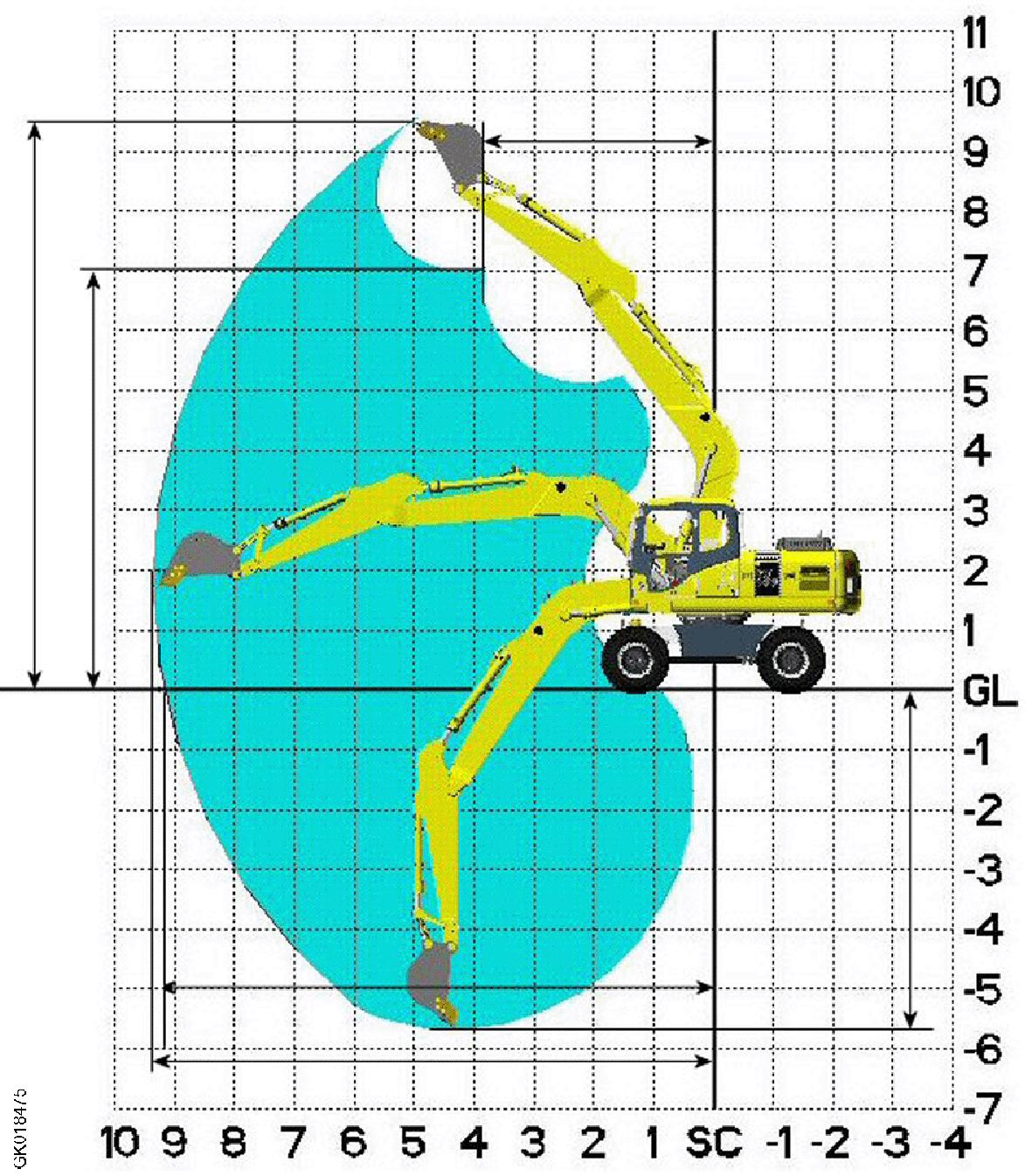
Working ranges
Working range: 1-piece boom
A Max. digging height9,9489,5629,756
BMax. dumping height6,9157,0647,236
CMax. digging depth5,3215,6765,966
DMin. swing radius3,5433,8294,057
E’Max. digging reach GL8,9079,2279,509
EMax. digging reach9,0619,3459,929
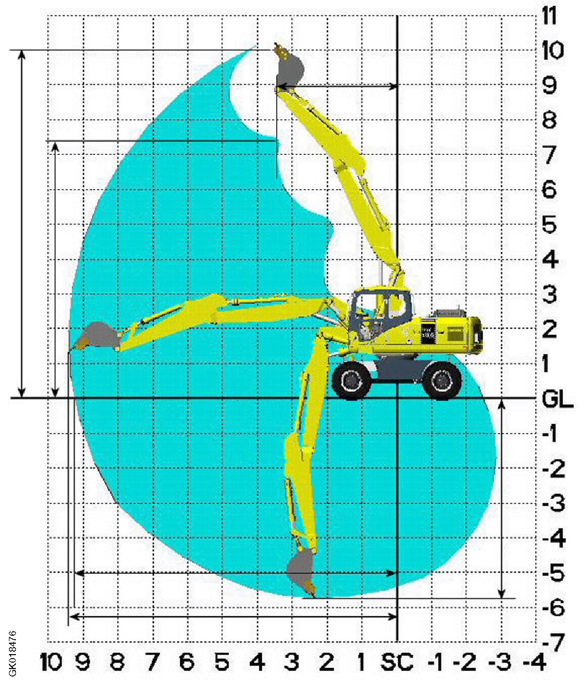
Working range: 2-piece boom
Arm length (mm)2,2502,600 2,900
A Max. digging height9,94210,12910,350
BMax. dumping height7,2837,4897,709
CMax. digging depth5,4005,7426,044
DMin. swing radius3,0653,3113,511
E’Max. digging reach GL8,9079,2279,509
EMax. digging reach9,0809,4019,683
Specifications
ArmUndercarriage attachment type
Front or rear blade18523185891868918755
Front and rear blade19372193891854619612
2.25m Without17666177331783317899
Front or rear outrigger18737188411890418970
2 outriggers and blade19594196981976119827
4 outriggers19809199511997620042
Front or rear blade18598186641876518831
Front and rear blade19455192511962219688
2.6m Without17742178081790917975
Rear outrigger18813189171898019046
2 outriggers and blade19670197741983719903
4 outriggers19885200272005220118
Front or rear blade18683187491885218918
Front and rear blade19540196061970819774
2.9m Without17827178931793518061
Front or rear outrigger18898190021906719133
2 outriggers and blade19449198591992319989
4 outriggers19970200362013920205
Weight will vary depending on specification
Weight with Tire 10.00-20 16PR NB38 MITAS
Operator (75 kg)
Standard equipment
Operating fluits
Filled fuel tank
Spoon (530 kg)
PERFORMANCEPW180-11
Bucket capacity (standard bucket) SAE0.8 m³
Creep speed2.5 km/h
Low speed10km/h
Travel speed
High speed Non German specification35 km/h German specification20 km/h
Swing speed11.5 rpm
Engine
ModelKomatsu SAA6D107E-3 diesel engine
Flywheel horsepower (NET) (ISO 14396)123 kW / 2.000 rpm
Starting motor24 V, 5,5 kW
Alternator24 V 90 A
Battery12 V 120AH x 2
CLICK HERE TO DOWNLOAD THE COMPLETE MANUAL
• Thank you very much for reading the preview of the manual.
• You can download the complete manual from: www.heydownloads.com by clicking the link below
• Please note: If there is no response to CLICKING the link, please download this PDF first and then click on it.
CLICK HERE TO DOWNLOAD THE
Machine model PW180-11
Serial Number H75051 and up Engine
No. of cylinders - bore x stroke Piston displacement
SAA6D107E-3-A 6-cylinder, water-cooled, in-line, direct injection, with turbo charger 6 - 107 x 124 6.6 {6600}
Max. speed at no load
Min. speed at no load
Performance Flywheel horsepower Max. torque
Starting motor Alternator Battery 24V, 5.5 kW 24V, 90 A 12V, 120 Ah x 2
Radiator core type Triple Cooler
(kgf/cm²) HPV125 (140), variable swash plate Piston type: 34.8 {355}
Piston type (with counter balance valve) Swing motor MSF 85P, Piston type (with safety valve, holding brake)
Weight table
This weight table is for use when handling components or when transporting the machine. Unit: kg
1-piece boom
Unit: kg
2-piece boom
Fuel, coolant and lubricants
ReservoirKind
Engine oil pan
Engine oil for KDPF used in cold terrain (Oil Change interval 250 hours)
Engine oil for KDPF (Oil Change interval 500 hours)
Swing machinery case PTO gear case
-25° C35° CKomatsu EOS5W30-LA
-25° C40° CKomatsu EOS5W40-LA
-20° C40° CKomatsu EO10W30-LA
-15° C50° CKomatsu EO15W40-LA
Engine oil-20° C40° CSAE 305,5
Powertrain oil-30° C50° CTO 300.75
Bio-oil-20° C30° CKomatsu B046-G4
Hydr-oil-20° C50° CKomatsu H046-HM
Power train oil-20° C50° CKomatsu TO10
Hydraulic system
Engine oil
-25° C40° CKomatsu EOS5W40-DH
-20° C40° CKomatsu EO10W30-DH
-15° C40° CKomatsu EO15W40-DH
Fuel tankDiesel fuel (EN590) -10° C -30° C 50° C 20° C ASTM Grade No. 2 ASTM Grade No 1 (for winter use)
Cooling system
Non-Amine Engine Coolant (AF-NAC) -30° C50° CAF-NAC (Note 4)3,´5 litre28 litre
S4
Axles 2,75m Front -3040Shell Spirax S4 TXM
litre10,4 litre Rear 17,8 litre17,8 litre
HubsFront-3040Shell Spirax S4 TXM2,5 litre2,5 litre
Transmission + clutchPowertrain Oil-30° C50° CTO 303 litre3 litre
Remark
•We recommend Komatsu genuine oil which has been specifically formulated and approved for use in engine and hydraulic work equipment applications.
•Only use high quality oils which meet internationally recognized specifications.
Standard value table for engine
Standard value table for engine: PW180-11
Performance Machine modelPW180-11
EngineSAA6D107E–3
ItemMeasurement conditionUnit
Engine speed at high idle
Engine speed at low idle
• Engine coolant temperature: 60 to 100 °C
• Hydraulic oil temperature: 45 to 55 °C
• Working mode: P (Power Mode)
• Fuel control dial: MAX (High idle) position
• Each control lever and control pedal: NEUTRAL
• Auto-deceleration switch: OFF
• Swing lock switch: ON
• Engine coolant temperature: 60 to 100 °C
• Hydraulic oil temperature: 45 to 55 °C
• Working mode: P (Power Mode)
• Fuel control dial: MIN (Low idle) position
• Each control lever and control pedal: NEUTRAL
Standard value for new machine Repair limit
rpm1850±701850±70
rpm1050±501050±50
ItemMeasurement conditionUnit
Boost pressure
Exhaust gas color
• Engine coolant temperature: 60 to 100 °C
• Hydraulic oil temperature: 45 to 55 °C
• Working mode: P (Power Mode)
• Fuel control dial: MAX (High idle) position
• Swing lock switch: ON
• Arm IN relief + One-touch power maximizing ON
• Engine coolant temperature: 60 to 100 °C
• Fuel control dial: MAX (High idle) position
• At arm IN relief
• After keeping it at normal condition for 5 seconds Engine outlet (between KVGT and KDPF) Bosch index
SCR outlet (exhaust
• Engine coolant temperature: 60 to 100 °C
• Hydraulic oil temperature: 45 to 55 °C
• Fuel control dial: MIN (Low idle) position
Mainbody
ItemMeasurement conditionUnit
Compression pressure
Blowby pressure
• Engine coolant temperature: 40 to 60 °C
• At cranking (engine speed): 250 to 280 rpm (reference)
• Engine coolant temperature: 60 to 100 °C
• Hydraulic oil temperature: 45 to 55 °C
• Working mode: P (Power Mode)
• Fuel control dial: MAX (High idle) position
• Swing lock switch: ON
• Arm IN relief + One-touch power maximizing ON
Pressure in Low-pressure circuit (fuel main filter inlet side)
Fuel control dial:
MAX (High idle) position
cranking
Pressure difference between main filter inlet side and outlet side
Fuel control dial: MAX (High idle) position
{2.11 to 6.63}
to
{2.11 to 5.1}
81 {Max. 0.83}
{2.11 to 6.63}
to
{2.11 to 5.1}
Fuel pressure
Return circuit
81
81 {Max. 0.83} At cranking
pressureFuel control dial:
(High idle) position
0.83}
18.6
0.19}
0.83}
18.6
0.19} At cranking
18.6 {Max. 0.19}
18.6 {Max. 0.19}
Pressure in negative pressure circuitFuel control dial: MAX (High idle) position mmHgMax. -305Max. -305
Fuel discharged volume, return amount and leakage amount
Supply pump discharged volumeAt cranking Min. 70Min. 70
Return rate from supply pumpFuel control dial: MIN (Low idle) position ml Max. 575Max. 575
At cranking (Min. 150 rpm) Max. 575Max. 575
Leakage from pressure limiterFuel control dial: MIN (Low idle) position
Max. 8Max. 8
At cranking (Min. 150 rpm)Max. 5 drops Max. 5 drops
Return rate from injectorFuel control dial: MIN (Low idle) position ml
At cranking (Min. 150 rpm)
Max. 150Max. 150
Max. 45Max. 45
Engine Speed
Measurement condition
Item
Engine speed at 2- pump relief
Engine speed at 2- pump relief + Onetouch power maximizing is ON
Speed when autodeceleration is operated
• Engine coolant temperature: 60 to 100 °C
• Hydraulic oil temperature: 45 to 55 °C
• Fuel control dial: MAX (High idle) position
• Working mode: P (Power Mode)
• Swing lock switch: ON
• Arm IN relief
• Engine coolant temperature: 60 to 100 °C
• Hydraulic oil temperature: 45 to 55 °C
• Fuel control dial: MAX (High idle) position
• Working mode: P (Power Mode)
rpm1700±1001700±100
• Arm IN relief + One-touch power maximizing ONrpm1950±1001950±100
• Engine coolant temperature: 60 to 100 °C
• Fuel control dial: MAX (High idle) position
• Auto-deceleration switch: ON
• Each control lever and control pedal: NEUTRAL rpm1050±1001050±100
ItemMeasurement conditionUnit
AdBlue/ DEF Pump Pressure Up Test
AdBlue/ DEF Injection Quantity Test
AdBlue/ DEF Line Heater
Relay 1 Test
AdBlue/ DEF Line Heater Relay 2 Test
AdBlue/ DEF Pump Heater Relay Test
AdBlue/ DEF Tank heater valve test
SCR Denitration Efficiency Test
AdBlue/DEF Pump Pressure Up Test within approximately 200 seconds after starting the test kPaMin. 800Min. 800
AdBlue/DEF Injection Quantity Test Injection amount after the test
AdBlue/DEF Line Heater Relay 1 Test within approximately 900 seconds after starting the test
V24.5±1.524.5±1.5
AdBlue/DEF Line Heater Relay 2 Test within approximately 900 seconds after starting the test
V24.5±1.524.5±1.5
AdBlue/DEF Pump Heater Relay Test within approximately 900 seconds after starting the test
V24.5±1.524.5±1.5
AdBlue/DEF Tank Heater Valve Test within approximately 900 seconds after starting the test
SCR Denitration Efficiency Test monitor display after the test
AdBlue/ DEF Injection Test
SCR Efficiency Test
V24.5±1.524.5±1.5
(Normal)
(Normal)
Abbreviation list.
STRUCTURE AND FUNCTION, MAINTENANCE STANDARD
AdBlue/DEF tank.
Layout drawing of BOOT-UP system.
Outline of CLSS
Basic Principle.
Operation for each function and valve
1.Unload valve
2.Introduction of LS pressure
3.LS bypass plug.
4.Pressure compensation valve
5.Area
6.Boom regeneration circuit
7.Arm regeneration circuit.
8.Swing bleeding valve.
9.Variable type pressure compensation valve (for service)
10.LS select valve.
Centre swivel joint
Travel PPC pedal.
Solenoid valve block with integrated ATT
ATT EPC valve assembly.
ON / OFF Solenoid valves (3 way valve)
2.Dimension of bucket.
CLICK HERE TO DOWNLOAD THE COMPLETE MANUAL
• Thank you very much for reading the preview of the manual.
• You can download the complete manual from: www.heydownloads.com by clicking the link below
• Please note: If there is no response to CLICKING the link, please download this PDF first and then click on it.
CLICK HERE TO DOWNLOAD THE
Abbreviation
Abbreviation list
• This list of abbreviations includes the abbreviations used in the text of the shop manual for parts, components, and functions whose meaning is not immediately clear. The spelling is given in full with an outline of the meaning.
• Abbreviations that are used in general society may not be included.
• Special abbreviations which appear infrequently are noted in th e text.
• This list of abbreviations consists of two parts. The first part is a list of the abbreviations used in the text of the manual, and the second part is a list of the abbreviations used in the circuit diagrams.
List of abbreviations used in the text
Abbreviation Actual word spelled out
ABSAnti-skid Brake System
Purpose of use (major applicable machine (*1), or component/system)
Travel and brake (HD, HM)
Explanation
When the tires skid (wheels stop rotating), the brakes are released, and when the wheels start to rotate, the brakes are applied again.
AISS Automatic Idling Setting SystemEngineThis function automatically sets the idle speed.
AJSSAdvanced Joystick Steering System
ARACAutomatic Retarder Accelerator Control
ARSCAutomatic Retarder Speed Control
ASRAutomatic Spin Regulator
Steering (WA)
Travel and brake (HD, HM)
Travel and brake (HD, HM)
Travel and brake (HD, HM)
ATTAttachmentWork equipment
BCVBrake cooling oil control valve
CANController Area Network
Brake (HD)
Communication and electronic control
CDRCrankcase Depression Regulator Engine
CLSSClosed-center Load Sensing System
Hydraulic system
CRICommon Rail InjectionEngine
A lever is used to perform the steering operations instead of a steering wheel. Moreover, it shifts gear and changes direction (FORWARD or RE- VERSE).
When the accelerator pedal is released while the machine is traveling downhill, this function automatically applies the retarder with a constant braking force.
When the accelerator pedal is released while the machine is traveling downhill, this function automatically applies the retarder to ensure that the machine speed does not accelerate above the speed set by the operator.
When the tires spin on soft ground surfaces, this function automatically uses the optimum braking force to drive both wheels.
A device that can be fixed onto the standard machine in order to enable it to do different jobs.
When the retarder is not being used, this valve bypasses part of the brake cooling oil to reduce the load on the hydraulic pump.
One of communication standards that is used in the network on the machine.
A regulator valve which is installed to KCCV ventilator. It is written as CDR valve and it is not used independently.
This system can simultaneously actuate multiple actuators regardless of the load (provides better combined operation than OLSS).
Engine controller electronically controls supply pump, common rail, and injector. This function maintains optimum fuel injection amount and fuel injection timing.
Abbreviation Actual word spelled out
Purpose of use (major applicable machine (*1), or component/system)
ECMElectronic Control Module Electronic control system
ECMVElectronic Control Modulation Valve
Transmission (D, HD, WA, etc)
ECSSElectronically Controlled Suspension System Travel (WA)
ECUElectronic Control UnitElectronic control system
Explanation
Electronic control device uses the signals from the sensors on the machine. These signals indi- cate the optimum actuation to the actuators. (Same as ECU)
Proportional electromagnetic valve that gradually increases oil pressure to engage clutch and reduces transmission shock.
This system ensures smooth high-speed travel by absorbing vibration of machine during travel with hydraulic spring effect of accumulator.
Electronic control device uses the signals from the sensors on the machine. These signals indi- cate the optimum actuation to the actuators. (Same as ECM)
EGRExhaust Gas Recirculation Engine
EMMSEquipment Manage- ment Monitoring System Machine monitor
EPC Electromagnetic Proportional ControlHydraulic system
FOPSFalling Object Protective Structure Cab and canopy
This function recirculates part of exhaust gas to combustion chamber in order to reduce combustion temperature, controls emission of NOx.
This system allows data (filter, oil replacement interval, malfunctions on machine, failure code, and failure history) from each sensor on the machine to be checked on the monitor.
This mechanism allows actuators to be operated in proportion to the current supplied.
This structure protects the operator's head from falling objects.
This performance is standardized as ISO 3449.
F-N-R Forward-Neutral-ReverseOperationForward - Neutral - Reverse
GPSGlobal Positioning System
GNSSGlobal Navigation Satellite System
HSSHydrostatic Steering System
HSTHydro Static Transmission
ICTInformation and Communication Technology
Communication (KOMTRAX, KOMTRAX Plus)
Communication (KOMTRAX, KOMTRAX Plus)
Steering (D)
Transmission (D, WA)
Communication and electronic control
IMAInlet Metering ActuatorEngine
Global Positioning System: This system uses satellites to determine the current location on the earth.
Global Navigation Satellite System: This system uses satellites such as GPS, GALILEO, etc. to determine the current location on the earth.
This function uses a combination of hydraulic motor and bevel shaft to control difference in travel speed of right and left tracks. Accordingly machine can turn without using steering clutch.
This function uses a combination of hydraulic pump and hydraulic motor for stepless shifting of the speed range without using gears.
A general term for the engineering and its social- ly applied technology of information processing and communication.
This valve is installed at inlet port of pump, and it adjusts fuel intake amount in order to control fuel discharged volume of supply pump. (Same as IMV)
*1: Code for applicable machine model
D: Bulldozer
HD: Dump truck
HM: Articulate dump truck
PC: Hydraulic excavator
WA: Wheel loader
List of abbreviations used in the circuit diagrams
AbbreviationActual word spelled out
A/CAir Conditioner
A/DAnalogue-to-Digital
A/MAir Mix Damper
ACCAccessory
ADDAdditional
AUXAuxiliary
BRBattery Relay
CWClockwise
CCWCounter Clockwise
ECUElectronic Control Unit
ECMElectronic Control Module
ENGEngine
EXGNDExternal Ground
F.G.Frame Ground
GNDGround
IMAInlet Metering Actuator
NCNo Connection
S/T Steering
STRG
SIGSignal
SOLSolenoid
STDStandard
OPT Option OP
PRESSPressure
SPECSpecification
SWSwitch
TEMPTemperature
T/CTorque Converter
T/MTransmission
UREA SCR system
SCR
Abbreviation for Selective Catalytic Reduction
Layout drawing of UREA SCR system
1: AdBlue/DEF tank
2: AdBlue/DEF filler port
3: AdBlue/DEF pump
4: AdBlue/DEF return hose
5: AdBlue/DEF tank coolant inlet hose
6: AdBlue/DEF tank coolant outlet hose
7: AdBlue/DEF suction hose
8: AdBlue/DEF tank pressure hose (low temperature side)
9: AdBlue/DEF pressure hose (high-temperature side) 10: SCR assembly 11: KDPF 12: AdBlue/DEF injector
AdBlue/DEF tank heating valve

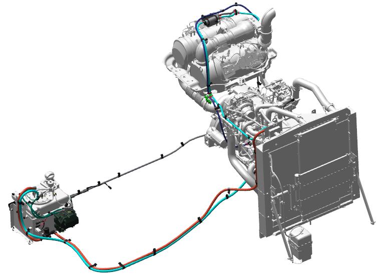

14: Ambient temperature sensor
15: Engine room temperature sensor
Detailed drawing of SCR assembly
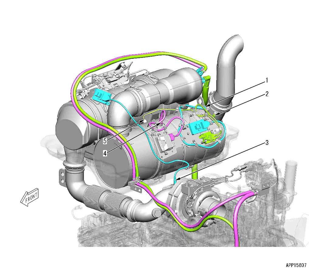
2. SCR outlet temperature sensor
3: Turbocharger outlet NOx sensor
4: Ammonia sensor
5: SCR temperature sensor
1: SCR outlet NOx sensor
Detailed drawing of AdBlue/DEF tank
1.AdBlue/DEF tank sensor
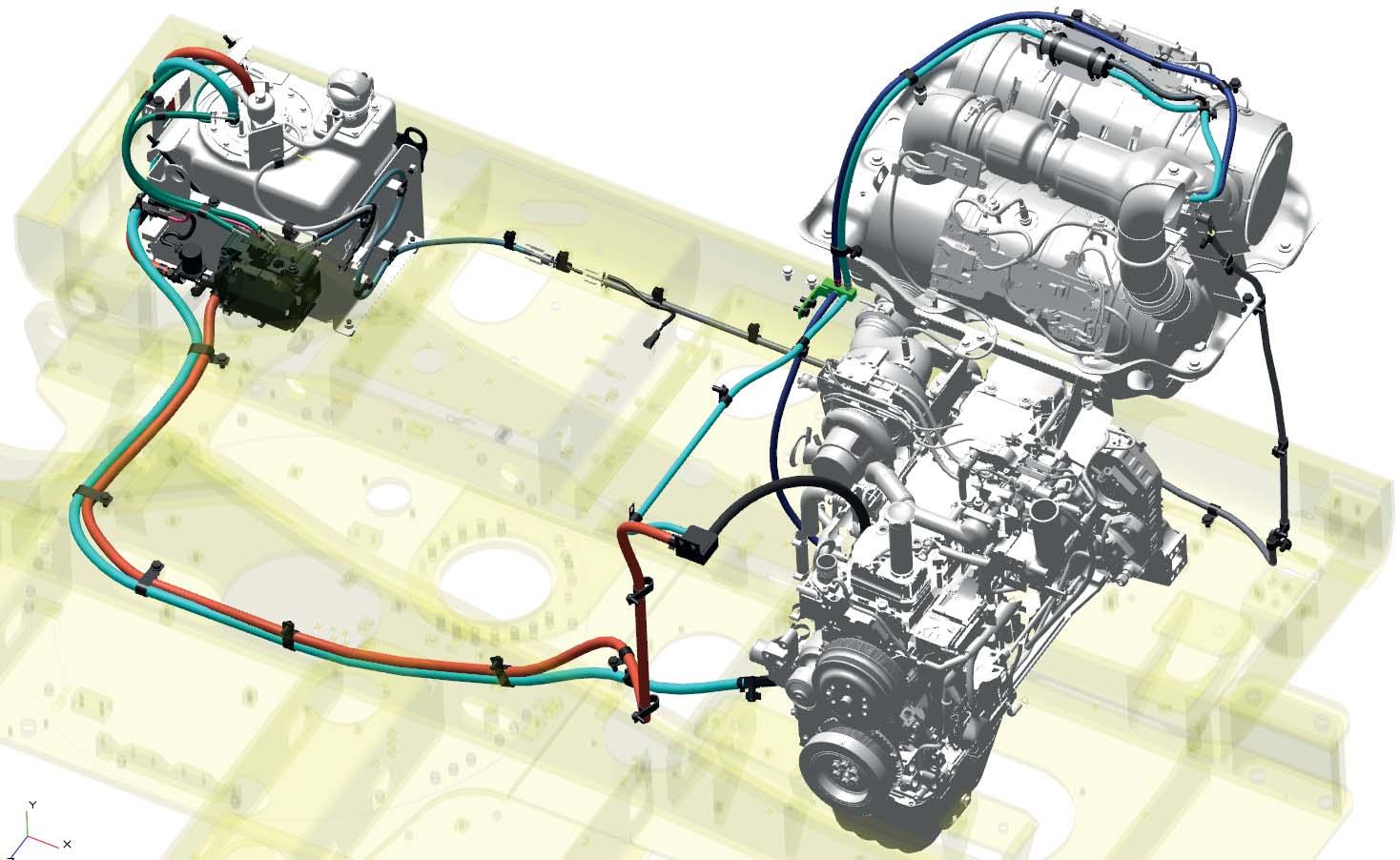
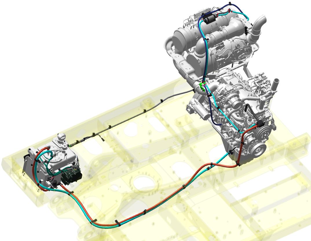
UREA SCR system diagram
REMARK
Four cylinder engine is shown in the figure.
A:Coolant inletB:Coolant outlet
1.Mass air flow and temperature sensor18.SCR temperature sensor controller
2.Engine19.SCR outlet NOx sensor
3.Engine controller20.SCR outlet NOx sensor controller
4.KDOC assembly21.Smart sensor
5.KDOC unit22.Ambient temperature sensor
6.Turbocharger outlet NOx sensor23.Engine room temperature sensor (*1)
7.Turbocharger outlet NOx sensor controller24.AdBlue/DEF system
8.KDOC inlet temperature sensor25.AdBlue/DEF tank heating valve
9.KDOC outlet temperature sensor26.AdBlue/DEF tank
10.KDOC temperature sensor controller27.AdBlue/DEF tank sensor
11.AdBlue/DEF mixing tube28.AdBlue/DEF suction line
12.AdBlue/DEF injector29.AdBlue/DEF return line
13.SCR assembly30.AdBlue/DEF pressure line
14.Upstream SCR catalyst31.AdBlue/DEF pump
15.Downstream SCR catalyst and ammonia oxidation catalyst (integrated type) 32.AdBlue/DEF line heater relay
16.SCR temperature sensor33.Machine monitor
17.SCR outlet temperature sensor
*1: There are some machine models which are not equipped with i t.
Function of UREA SCR system
1.Engine5.AdBlue/DEF injector
2.Engine controller
3.AdBlue/DEF pump
4.AdBlue/DEF tank
6.KDOC
7.SCR catalyst
8.Downstream SCR catalyst and ammonia oxidation catalyst (integrated type)
• Urea SCR system is a device which converts toxic nitrogen oxides (NOx) in the exhaust gas into harmless nitrogen and water.
• By spraying AdBlue/DEF into the exhaust gas, it decomposes and hydrolyzes to form ammonia (NH3) and the ammonia selectively reacts with nitrogen oxides for the conversion to nitrogen and water.
A4P16366
Function of AdBlue/DEF system
1.AdBlue/DEF tank
2.AdBlue/DEF suction hose
3.AdBlue/DEF Pump
3A.Selector valve
3B.Pump
3C.AdBlue/DEF filter
3D.Pressure sensor
4.AdBlue/DEF return hose
5.AdBlue/DEF pressure hose
6.AdBlue/DEF injector
• AdBlue/DEF system consists of AdBlue/DEF tank (1), AdBlue/DEF hoses (2), (4), (5), AdBlue/DEF pump (3), and AdBlue/DEF injector (6). It injects AdBlue/DEF into mixing tube.
• This system automatically starts operation after starting the engine.
• Since AdBlue/DEF freezes at -11 oc, this system has a heating function to thaw AdBlue/DEF and to prevent AdBIue/ DEF from freezing
Function of AdBlue/DEF injection system
•The AdBlue/DEF pump pressurizes AdBlue/DEF and delivers it into the AdBlue/DEF mixing tube through the AdBlue/DEF injector.
•The amount of AdBlue/DEF injection is controlled by the Engine Controller.
•The amount of AdBlue/DEF injection is calculated based on the information of the turbocharger outlet NOx sensor, the SCR catalyst temperature sensor, the SCR outlet temperature sensor, the ammonia sensor, the SCR outlet NOx sensor and the exhaust gas flow rate.
•AdBlue/DEF injection is also controlled by the system temperature because Urea SCR systems are not effective in low temperature. For the monitoring of the system temperature, the KDPF outlet temperature sensor is used in addition to the SCR temperature sensors.
•If any abnormality is detected in any of the sensors that are used for the calculation of the amount of AdBlue/ DEF injection and the monitoring of the system temperature, the Engine Controller commands termination of AdBlue/DEF injection. When this occurs, alerts will be activated and failure codes will be registered.
•Some abnormalities may cause large amount of urea precipitation inside the AdBlue/DEF mixing tube and result in deposit of urea on the inner surfaces. If it continues and urea deposit accumulates AdBlue/DEF injection can be blocked at the AdBlue/ DEF injector or the exhaust gas flow can be choked in the passages.
AdBlue/DEF purge function
•The AdBlue/DEF purging is incorporated to purge remaining AdBlue/DEF in the AdBlue/DEF injector, AdBlue/DEF hoses and the AdBlue/DEF pump to prevent AdBlue/DEF from solidifying inside by precipitation or freezing.
•The AdBlue/DEF purging is activated automatically when the engine is shut down or the ambient temperature falls so low that the heating systems is not capable of maintaining fluidity of AdBlue/DEF.
•In the case of the AdBlue/DEF purging of the engine shutdown, the purging operation continues several minutes after the engine stops. Once the purging operation completes, the Engine Controller shuts itself down automatically.
NOTE
Do not turn the battery disconnect switch to the OFF position till the System Operating Lamp in the battery box turns off. The System Operating Lamp will go out when the system shuts itself down after the purging operation completes.
Function of heating system
• This function has the thawing mode and freeze prevention mode.
• Thawing mode is the function to thaw the frozen AdBlue/ DEF.
•After starting engine, if the engine controller judges that AdBlue/DEF must be thawed, this function au- tomatically heats the system.
•At this time, pressure control of AdBlue/DEF pump and injection of AdBlue/DEF are not performed until the thawing is completed.
• Freeze prevention mode is the function to keep AdBlue/DEF warm to prevent it from freezing.
•This function automatically heats the system to prevent it from freezing while operating the machine, if engine controller judges that AdBlue/DEF could be frozen.
•This function stops the pressure control of AdBlue/DEF pump and injection of AdBlue/DEF if it judges that AdBlue/DEF is frozen while operating the machine. Thawing and freeze prevention mode are controlled by sensor and the sensors vary by devices which AdBlue/DEF system consists of. The following table shows the relationship among the object devices, heating system and the sensors for each mode.
CLICK HERE TO DOWNLOAD THE COMPLETE MANUAL
• Thank you very much for reading the preview of the manual.
• You can download the complete manual from: www.heydownloads.com by clicking the link below
• Please note: If there is no response to CLICKING the link, please download this PDF first and then click on it.
CLICK HERE TO DOWNLOAD THE
Object devices for function of AdBlue/DEF thawing and preventing from freezing
AdBlue/DEF suction hose and return hoses
AdBlue/DEF pressure hose (low- temperature side)
AdBlue/DEF pressure hose (high- temperature side)
Heating systemSensors for Thawing mode
Sensors for Freeze Pre- vention mode
Heater around hoseAmbient temperature sensorAmbient temperature sensor
Heater around hoseEngine room temperature sensorEngine room temperature sensor
AdBlue/DEF pumpHeater which is built in the pump
AdBlue/DEF tankCirculation of coolant
Inducement strategy
AdBlue/DEF pump temperature sensor Ambient temperature sensor
AdBlue/DEF tank temper- ature sensor
• The purpose of inducement is to prompt the operator to perform maintenance or repair on the emissions control system
• Inducement strategy is a control action to ensure prompt correction of various failures in the engine emissions control system. It requires actions to limit engine performance and defines required indication such as warning lamps and messages, as well as alarms while the control actions are imposed. The warning steps of Inducement are different between for North America and for European Union.
The categories of abnormalities that have triggered Inducement are displayed on the “SCR Information” screen of the machine monitor.
AdBlue/DEF tank temper- ature sensor
Inducement strategy when the AdBlue/DEF level in the tank becomes low
• When the AdBlue/DEF level in the tank becomes low, AdBlue/DEF level caution lamp on the machine monitor lights up, the Audible alert sounds, the action level is displayed and Inducement strategy including engine power deration is activated.
• The Inducement strategy progresses in 4 levels from Warning, Continuous Warning, Low-Level Inducement, and Severe Inducement.
• Up to the start of Severe Inducement the start of each warning step is triggered by the amount of
• AdBlue/DEF in the AdBlue/DEF tank.
• The Inducement strategy status can be checked on “SCR Information” screen of the user menu.
• The table shows warning indications and engine power derations by each Inducement strategy status. *1: It is shown the value of Monitoring ID 19111: “AdBlue/DEF Level Corrected”. Status AdBlue/DEF level (*1) (AdBlue/ DEF level gauge) Machine
1Warning 10% (The bottom two gradations light on)
2 Continuous Warning (Warning 2) 5% (Within the gradation of the second from the bottom)
1: DEF low level warning appears. Red

2: Without treatment, engine power will be derated. Red
3
Low level Inducement (Inducement 1) 2.5% (The gradation of the end of the bottom lights on)
4 Severe Inducement (Inducement 2) 0% (All gradations lights off)
3: Engine power is under deration. Red Red

4: Engine power is under heavy deration. Red Red

Triplet (*4) Short intermittently (*5)
(*2)
CA3497 (AdBlue/DEF level low error 1)
CA3498 (AdBlue/DEF level low error 2) No deration
Long intermittently
Continuously
CA1673 (AdBlue/DEF level low error 3)
Torque: over 25%
CA1673 CA3547 (AdBlue/DEF level low error 4)
Torque: over 50% and RPM: over 40%
*2: These failure codes are displayed on “Current Abnormality” in the operator mode, or “Abnormality Record” in the service mode. For the failure codes, see TROUBLESHOOTING, “TROUBLESHOOTING POINTS FOR UREA SCR SYSTEM”.
*3: These percentages show a torque reduction ratio from the full torque curve, and a speed reduction ratio from the rated speed.
*4: Construction equipment with crawler
*5: Construction equipment with wheel
Inducement strategy when abnormality is found in the AdBlue/DEF quality or in the UREA SCR system devices
• When any abnormality is found in the AdBlue/DEF quality or in the Urea SCR system tampering or fault, AdBlue/DEF caution lamp on the machine monitor lights up, the Audible alert sounds. If time has elapsed after any abnormality is generated, not only the warning by AdBlue/DEF caution lamp on the machine monitor and Audible alert, but also an action level is displayed, Inducement strategy is activated and then the engine output is reduced.
• The Inducement strategy status and the categories of abnormalities can be checked on the “SCR Information” screen of the machine monitor.
• The table shows warning indications and engine power derations by each Inducement strategy status.
(*1)
1Warning 5 hour
Message of SCR Information Caution lamp (Action level)

Tone of audible alert failure code for abnormality( *2), (3)
Failure code for Inducement strategy status (*4)
1: Please inspect and maintain SCR system. Yellow Yellow No sound CA3571 CB3571 No indication No deration

2 Continuous Warning (Warning 2) 10 hours 2: Without treatment, engine power will be derated. Yellow Yellow


Triplet (*6) Short intermittently (*7) CA3571 CB3571
3 Low level Inducement (Inducement 1) 20 hours 3: Engine power is under deration. Red Red Long intermittently CA3571 CB3571

4 Severe Inducement (Inducement 2) Until repairing 4: Engine power is under heavy deration. Red Red


Continuously CA3571 CB3571
AS00R2 (Warning 2 (SCR Device Abnormality) No deration
AS00R3 (Inducement 1 (SCR Device Abnormality)
Torque: over 25%
AS00R4 (Inducement 2 (SCR Device Abnormality)
Torque: over 50% and RPM: over 40%
1: Elapsed time of each stage describes an accumulated time advancing to the next stage after starting “Warning” stage. Fin al Inducement is not cleared till abnormality is repaired.
*2: These failure codes are displayed on “Current Abnormality” in the operator mode, or “Abnormality Record” in the service mode. The failure code shown here is an example of failure code which is displayed on the machine monitor when an abnormality occurs. For the failure codes, see TROUBLESHOOTING, “TROUBLESHOOTING POINTS FOR UREA SCR SYSTEM”.
*3: The failure code which starts with CB may be displayed for the machine equipped with aftertreatment devices branching off to 2 lines.
*4: These failure codes are displayed on “Current Abnormality” in the operator mode, or “Abnormality Record” in the service mode.
*5: These percentages show a torque reduction ratio from the full torque curve, and a speed reduction ratio from the rated speed.
*6: Construction equipment with crawler
*7: Construction equipment with wheel
Inducement strategy when abnormality is found in the KDOC system by the IREA SCR system
• The Inducement strategy is different if Inducement is triggered by abnormalities in KDOC. Although the total steps are the same and 4, warning indications are different and engine power deration (Over 25% torque reduction) starts from that of “Warning”.
• The table shows warning indications and engine power derations by each Inducement strategy status.
Status
time (*1) Machine monitor Engine
(*4) Message of SCR Information Caution lamp (Action level) Tone of audible alert failure code for abnormality( *2)
1Warning5 hour 1: Please inspect and maintain SCR system


2 Escalated Warning (Warning 2) 10 hours 2: Without treatment, engine power will be derated.


Long intermittently
Triplet (*5) Short intermittently (*6)
Failure code for Inducement strategy status (*3)
AS00R2 (Warning 2 (SCR Device Abnormality)
Torque: over 25% 3 Mild Inducement (Inducement 1) 20 hours 3: Engine power is under deration.
Long intermittently


AS00R3 (Inducement 1 (SCR Device Abnormality)
Torque: over 25% 4 Severe Inducement (Inducement 2) Until repairing 4: Engine power is under heavy deration.
AS00R4 (Inducement 2 (SCR Device Abnormality)
Torque: over 50% and RPM: over 40%
1: Elapsed time of each stage describes an accumulated time advancing to the next stage after starting “Warning ”stage. Fin al Inducement is not cleared till abnormality is repaired.
*2: These failure codes are displayed on “Current Abnormality” in the operator mode, or “Abnormality Record” in the service mode. The failure code shown here is an example of failure code which is displayed on the machine monitor when an abnormality occurs. For the failure codes, see TROUBLESHOOTING, “TROUBLESHOOTING POINTS FOR UREA SCR SYSTEM”.
*3: These failure codes are displayed on “Current Abnormality” in the operator mode, or “Abnormality Record” in the service mode.
*4: These percentages show a torque reduction ratio from the full torque curve, and a speed reduction ratio from the rated speed.
*5: Construction equipment with crawler
*6: Construction equipment with wheel
Inducement strategy when abnormality is found in the EGR system by the IREA SCR system devices
The Inducement strategy is different if Inducement is triggered by abnormalities in EGR. Although the total steps are the same and 4, warning indications are different and engine power deration (Over 25% torque reduction) starts from that of “Warning”. The table shows warning indications and engine power derations by each Inducement strategy status
Machine monitor
Status Elapsed time (*1)
1Warning5 hours
Message of SCR Information Caution lamp (Action level)
Tone of audible alert failure code for abnormality( *2)
1: Please inspect and maintain SCR system. Red Red Long intermittently

2 Continuous Warning (Warning 2) 10 hours
2: Without treatment, engine power will be derated. Red Yellow Red

Triplet (*5) Short intermittently (*6) CA2272

3 Low level Inducement (Inducement 1) 20 hours 3: Engine power is under deration. Red Red Red Long intermittently


4 Severe Inducement (Inducement 2) Until repairing 4: Engine power is under heavy deration. Red Red Red Continuously CA2272
Failure code for Inducement strategy status (*3)
Engine deration (*4)
Torque: over 25%
AS00R2 (Warning 2 (SCR Device Abnormality)
Torque: over 25%
AS00R3 (Inducement 1 (SCR Device Abnormality)
Torque: over 25%
AS00R4 (Inducement 2 (SCR Device Abnormality)
Torque: over 50% and RPM: over 40%
*1: Elapsed time of each stage describes an accumulated time advancing to the next stage after starting “Warning” stage. Fin al Inducement is not cleared till abnormality is repaired
*2: These failure codes are displayed on “Current Abnormality” in the operator mode, or “Abnormality Record” in the service mode. The failure code shown here is an example of failure code which is displayed on the machine monitor when an abnormality occurs. For the failure codes, see TROUBLESHOOTING, “TROUBLESHOOTING POINTS FOR UREA SCR SYSTEM”.
*3: These failure codes are displayed on “Current Abnormality” in the operator mode, or “Abnormality Record” in the service mode.
*4: These percentages show a torque reduction ratio from the full torque curve, and a speed reduction ratio from the rated speed.
*5: Construction equipment with crawler
*6: Construction equipment with wheel
Function of temporary restoration from inducement
• Temporary Restoration from Inducement is one of the Inducement strategies allowed to be included in Urea SCR systems. In case the Urea SCR system advances to “Severe Inducement”, engine power is derated heavily. This may cause difficulties of moving the machine to a safe place for adding AdBlue/DEF or troubleshooting and correcting abnormalities of the Urea SCR system. For temporary remedies from these difficulties the operator can restore engine power for a short time to the deration of “Low-Level Inducement” through the machine monitor. Note that “Temporary Restoration from Inducement” does not regain full en- gine power
• “Temporary Restoration from Inducement” can be activated only when the Urea SCR system is in “Severe Inducement”. The maximum duration is limited to 30 minutes in each restoration operation, and 3 operations are allowed. All the abnormalities of the Urea SCR system need to be corrected to regain another restoration capability.
• To activate Temporary Restoration, follow the procedures described below
REMARK
For the operating procedure on this function, refer to "TEMPORARY RESTORATION FROM INDUCEMENT" on the OPERATION section in the Operation and Maintenance Manual.
Inducement strategy for abnormality recurrence within 40 hours
• The Urea SCR system continuously monitors its operation conditions and stores information on inappropriate operations including malfunctions.
• The stored information is utilized to monitor recurrences of abnormalities, “Abnormality Counter”. “Abnormality Counter” is required by the authorities. The abnormality counting spans 40 hours and it monitors the abnormalities that trigger Inducement other than the amount of AdBlue/DEF in the tank.
• If another abnormality/abnormalities is detected within 40 hours after the previous abnormalities were corrected, regardless of the level of the previous Inducement and whether the new abnormality/abnormalities is the same as the previous ones or not, it is judged as a recurrence.
• If a recurrence occurs, the Inducement strategy will be activated.
• Inducement in the recurrence resumes counting time at the time when the previous abnormalities were corrected if the previous Inducement is in “Warning”, “Continuous Warning” or “Low-Level Inducement”. The alerts resume the previous Inducement.
• If the time the previous abnormalities were corrected is in “Severe Inducement”, Inducement in the recur- rence starts from “Low-Level Inducement” but the remaining time to “Severe Inducement” is 1 hour or 2 hours depending on abnormalities. If the 1 hour or 2 hours are used up without correcting the new abnormalities, Inducement will advance to “Severe Inducement” and engine power will be derated heavily.
Component parts of UREA SCR system
SCR
Abbreviation for Selective Catalytic Reduction
AdBlue/DEF MIXING TUBE
Structure of AdBLUE/DEF mixing tube
The shape is subject to machine models.
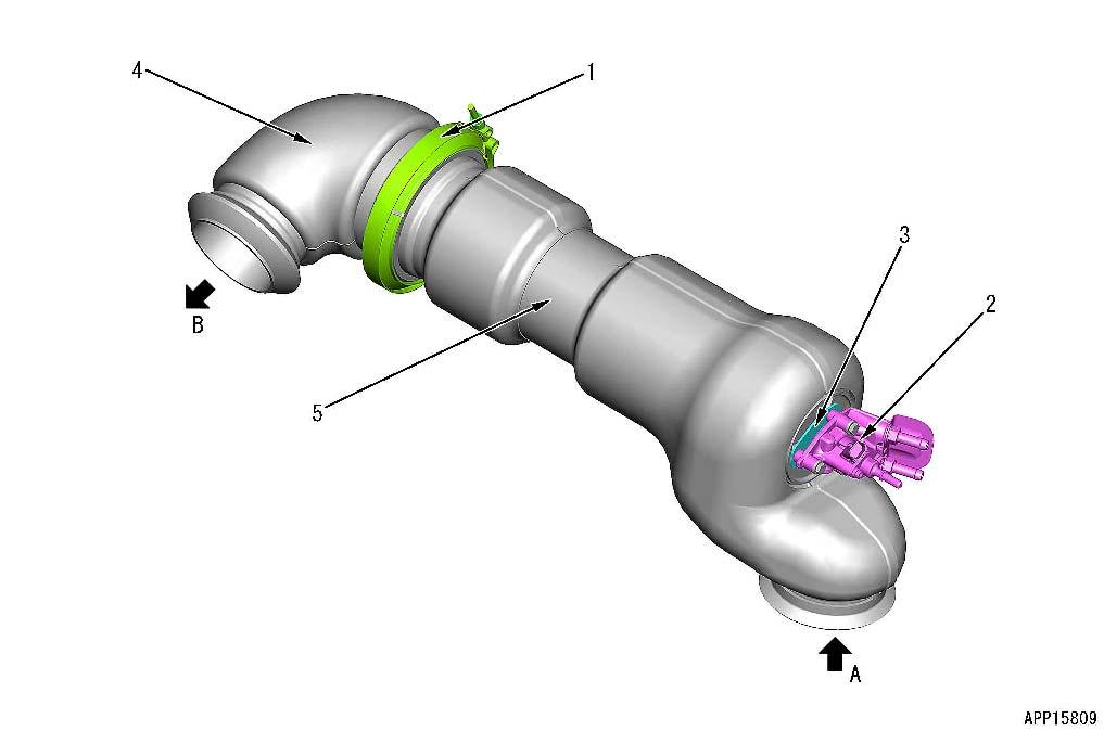
A.Exhaust gas inlet (from KDOC)B.Exhaust gas outlet (to SCR)
1.AdBlue/DEF mixing tube (connector)4.Gasket for AdBlue/DEF injector
2.Clamp5.AdBlue/DEF injector
3.AdBlue/DEF mixing tube (tube)
Function of AdBlue/DEF mixing tube
It mixes AdBlue/DEF injected from AdBlue/DEF injector with exhaust gas, and decomposes it to ammonia which is needed to purge NOx from SCR assembly
SCR assembly
SCR
Abbreviation for Selective Catalytic Reduction
Structure of UREA SCR assembly
The shape is subject to machine models.
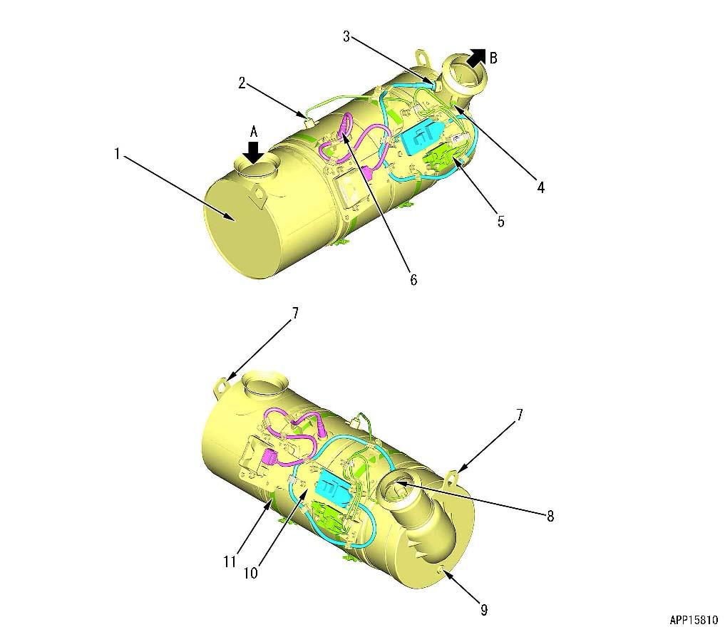
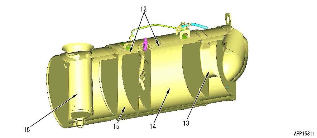
A.From AdBlue/DEF mixing tube B: To exhaust pipeB.To exhaust pipe
1.SCR body9.Sensor table
2.SCR temperature sensor10.AdBlue/DEF injector
3.SCR outlet NOx sensor11Sensor table band
4SCR outlet temperature sensor12Catalyzer hold mat
5: Temperature sensor controller13Water dam
6 Ammonia sensor14Downstream SCR catalyst and ammonia oxidation catalyst (integrated type)
7Hanger plate15Upstream SCR catalyst
8water baffle16Rectifier tube
•SCR assembly consists of rectifier tube (10) equalizing the distribution of flow speed by leading exhaust gas, upstream SCR catalyst (11), downstream SCR catalyst, ammonia oxidation catalyst (integrated type) (12), and water dam (13) which prevents rain water from entering into downstream SCR catalyst and ammonia oxidation catalyst (integrated type) (12) while exhausting gas.
•Ammonia oxidation catalyst (a part of 12) oxidizes ammonia to water and nitrogen with ammonia oxidation catalyst (a part of 12) to prevent ammonia which is supplied to SCR assembly from being released out be- cause SCR catalyst (a part of 12, 11) cannot completely consume it.
•SCR assembly has SCR temperature sensor (2), SCR outlet temperature sensor (5), and SCR outlet NOx sensor (3) (1 piece each). These sensors monitor the function of SCR catalyst. These sensors are used for various troubleshooting.
•Rectifying tube (10) equalizes the distribution of exhaust gas flow speed.
•SCR catalyst (a part of 12, 11) uses the ceramic honeycomb
•The catalyzer holding mat (9) is made of a specific fiber and protects the ceramic catalyst against vibrations by the engine and the machine body. It also protects the outer periphery of SCR assembly against a heat transfer of the ceramics during operation.
•Water dam (13) is located at the upstream side of the outlet and prevents rainwater from entering into downstream SCR catalyst unit and ammonia oxidation catalyst (integrated type) (12).
•Water baffle (4) is located at the downstream side of the outlet and prevents rainwater at outlet from splashing over the detection part of NOx sensor.
AdBlue/DEF tank
Structure of AdBlue/DEF tank
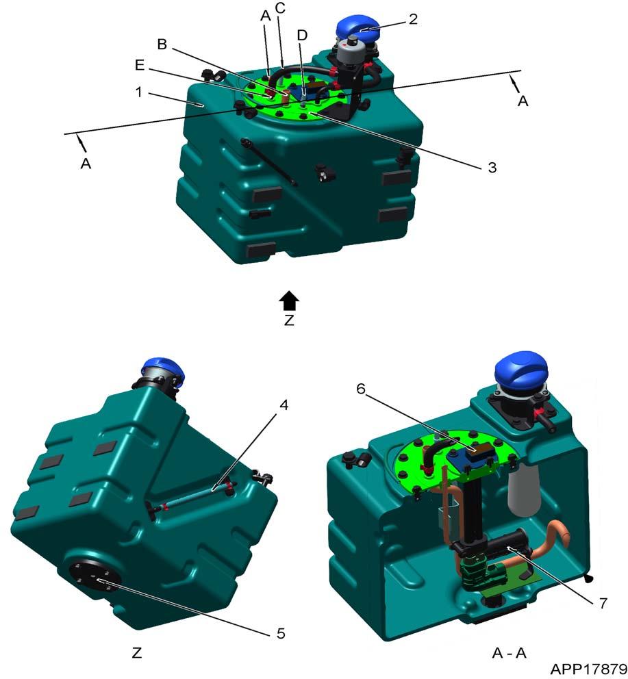
A.Coolant outletD.To AdBlue/DEF pump
B.Coolant inletE.To breather
C.From AdBlue/DEF pump
1.AdBlue/DEF tank5Drain plug
2.AdBlue/DEF filler cap6AdBlue/DEF tank sensor
3.Sensor flange assembly7AdBlue/DEF tank filter
4.Sight gauge
CLICK HERE TO DOWNLOAD THE COMPLETE MANUAL
• Thank you very much for reading the preview of the manual.
• You can download the complete manual from: www.heydownloads.com by clicking the link below
• Please note: If there is no response to CLICKING the link, please download this PDF first and then click on it.
CLICK HERE TO DOWNLOAD THE
AdBlue/DEF tank sensor
Structure of AdBlue tank sensor
REMARK
The shape is subject to machine models.
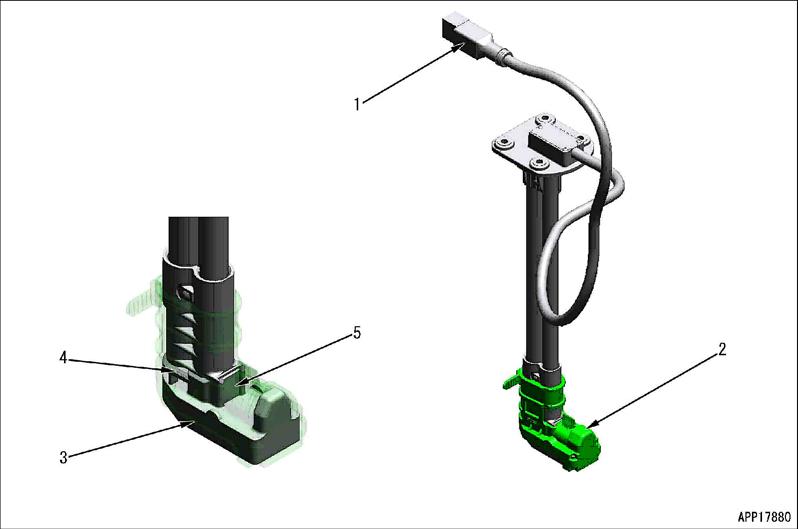
1.Connector4.Level sensing part
2.Cover5.Concentration Sensing part
3.Temperature sensing part
Function of AdBlue tank sensor
• This sensor is installed to AdBlue/DEF tank and outputs AdBlue/DEF level, AdBlue/DEF concentration, and AdBlue/ DEF temperature through CAN communication.
• AdBlue/DEF level and AdBlue/DEF concentration are measured by using ultrasonic wave.
• When the tank is frozen or empty, AdBlue/DEF level and AdBlue/DEF concentration are not measured.
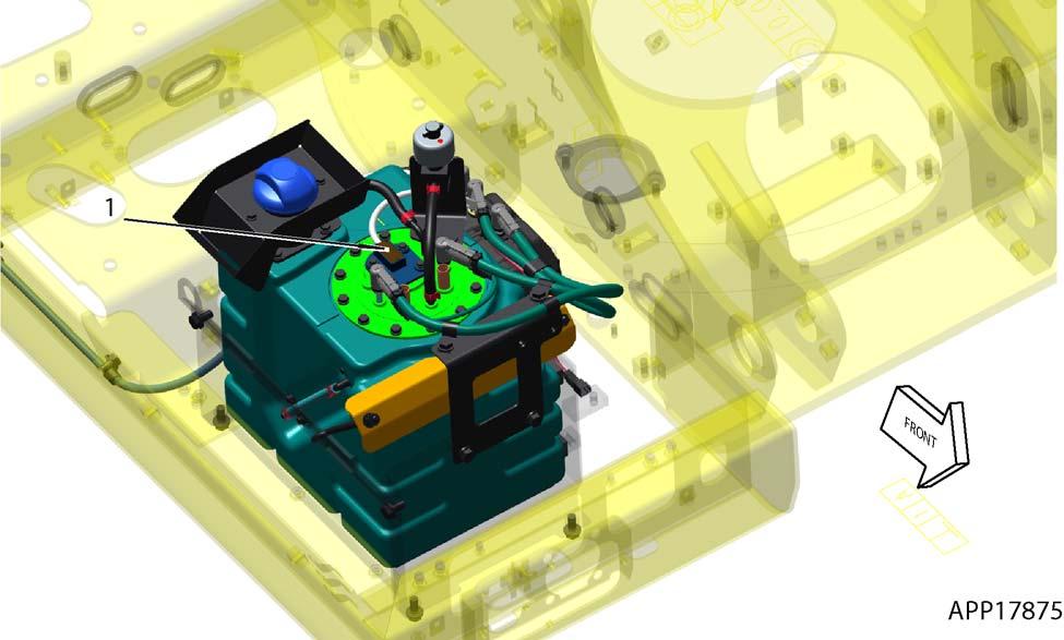
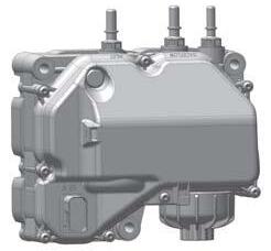
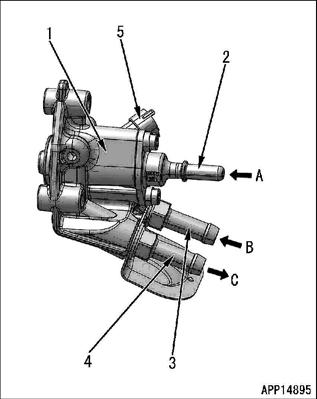
AdBlue/DEF pump
Structure of AdBlue pump
A.Suction from AdBlue/DEF tank
B.Return to AdBlue/DEF tank
C.Pressurized sending to AdBlue/DEF injector
1.AdBlue/DEF pump
2.AdBlue/DEF inlet connector
3.AdBlue/DEF backflow connector
4.AdBlue/DEF outlet connector
5.Electric connector
6AdBlue/DEF filter cap
7AdBlue/DEF filter (built-in
•The followings are built-in: The filter to collect the dust in AdBlue/DEF, the valve to switch the flow direction when purging, and the heater to thaw AdBlue/DEF when it is frozen.
•It purges AdBlue/DEF from AdBlue/DEF tank, pressurizes it to 900 kPa {9.18 kgf/cm2}, and sends it to AdBlue/DEF injector
•To prevent wrong connection of connectors, the backflow connectors are white and can be distinguished from others. The sizes of inlet connector and outlet connector are different and they cannot be connected each other
AdBlue/DEF injector
Structue of AdBlue/DEF injector
A.Pressurized sending from AdBlue/DEF pumpC.Coolant outlet
B.Coolant inlet3.Coolant inlet connector
1.AdBlue/DEF injector4.Coolant outlet connector
2.AdBlue/DEF inlet connector5Electric connector
Function of the AdBlue/DEF injector
•It injects AdBlue/DEF which is pressurized by AdBlue/DEF pump into AdBlue/DEF mixing tube.
•The injection amount is controlled by the valve opening or closing time while the pressure is constant.
•It circulates the engine coolant to prevent it from being heated by the heat from the exhaust pipe.
Operation of the AdBlue/DEF injector
Principle of injection of the injector is described. Following figure shows the state of injection
• Engine controller sends the electrical signal to control AdBlue/DEF injector
• Solenoid (4) moves seal ball (2), and seal ball (2) leaves from injection port (1) to make opening state.
• When the electrical signal is not sent, seal ball (2) closes injection port (1) with spring force (3), so AdBlue/DEF is not injected.
AdBlue/DEF hose
Structue of AdBlue/DEF hose
1.Connector5.Insulation tape
2.Housing6.Heating wire
3.Coupling7.Nylon tube
4.Corrugated tube
• It is used as AdBlue/DEF piping between AdBlue/DEF tank and AdBlue/DEF pump or between AdBlue/DEF pump and AdBlue/DEF injector.
• The shape of the engaging portion between AdBlue/DEF tank and AdBlue/DEF pump or AdBlue/DEF injec- tor pin is based on 3/8 inches or 5/16 inches of SAE J2044. It can be disconnected or connected with one touch.
• TThere are 2 types of nylon tubes of its outside diameter 5?mm and 8?mm. Choose the suitable one accord- ing to the model and the part to use.here are 2 types of hose end shape such as straight shape and 90 deg. elbow shape.
Structue of AdBlue/DEF hose
• In the cold weather, the specified current flows in the heating wire immediately after the engine is started. It heats nylon tube and thaws AdBlue/DEF which has frozen in the nylon tube.
• It also keeps temperature constant to prevent AdBlue/DEF from freezing again while machine is operated.
AdBlue/DEF tank heating valve
Structure of AdBlue/DEF tank heating valve
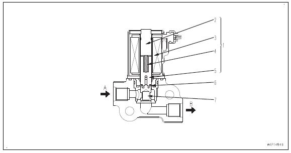
A.Engine coolant inlet
B.Engine coolant outlet
1.Solenoid5.Plunger
2.Solenoid core
3.Solenoid coil
4.Spring
Function of AdBlue/DEF tank heating valve
6.Diaphragm
7.Valve
• AdBiue/DEF tank heating valve thaws AdBiue/DEF tank, and opening/closing of the valve (7) is done by solenoid (1).
• The opening position of valve is fixed and the control is only for opening/closing. When the solenoid (1) is de-energized, the valve is closed.
• Diaphragm (6) prevents entering of engine coolant into solenoid (1).
Operation of AdBlue/DEF tank heating valve
When solenoid coil (3) is energized, solenoid core (2) is magnetized and pull plunger (5) to open valve (7)
• which is directly connected to plunger (5).
• When solenoid coil (3) is de-energized, solenoid core (2) loses pulling force and plunger (5) is pushed down by spring (4) and valve (7) is closed.
BOOT-UP system
Layout drawing of BOOT-UP system
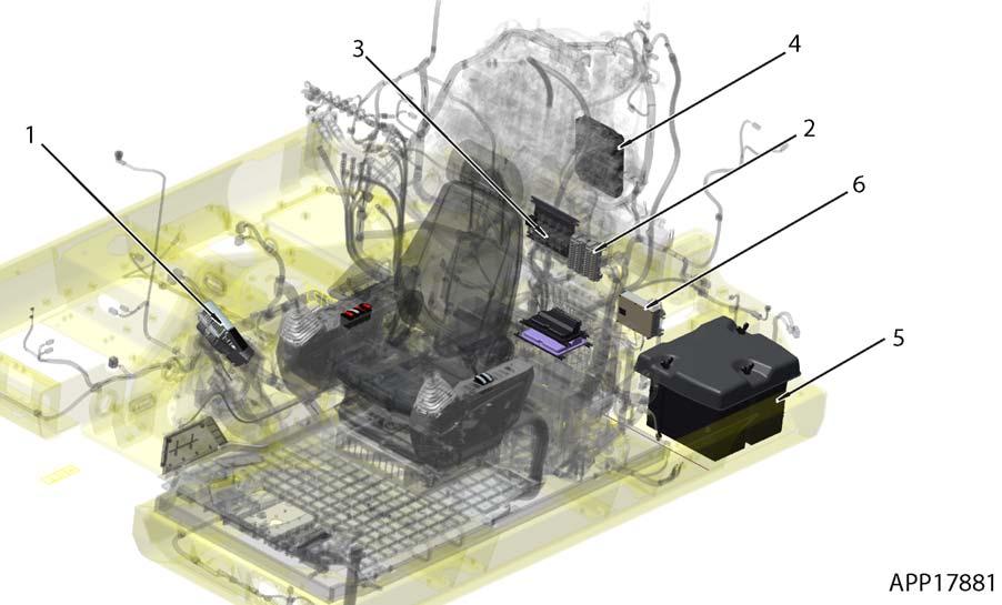
1.Machine monitor4.Engine controller
2.Fuse box5.Battery
3.Pump controller6.KOMTRAX terminal
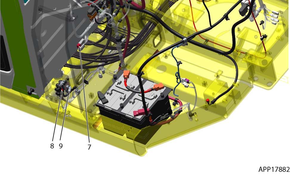
7.Fusible link9.Battery disconnect switch
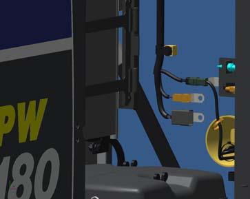
8.System operating lamp
System operating lamp system
System operating lamp system diagram
1.Battery disconnect switch
7.Engine controller
2.Battery8Pump controller
3.Fusible link
4.Fuse box
5.System operating lamp
6.Machine monitor
*1 = Machine with ID key
Function of system operating lamp system
9KOMTRAX terminal
10ID key controller (*1)
11Machine controller
12KomVision controller
System operating lamp is lit while any of controllers are in operation. To prevent the abnormal end of the disc onnection of the battery power supply circuit while the controllers are in operation, check the operation state with this lamp.
REMARK
• Before shutting off the battery power supply circuit, turn the starting switch to "OFF" position, and check that the system operating lamp goes off , then turn the battery disconnect switch to "OFF" position.
• If the battery disconnect switch is turned to "OFF" position (the battery power supply circuit is OFF) while the system operating lamp is lit, data loss error of controller may occur. Never operate the battery disconnect switch while the system operating lamp is lit.
• The system operating lamp goes off in 5 minutes after the starting switch is turned to "OFF" position.
• The system operating lamp may sometimes light up while the starting switch is in "OFF" position, because KOMTRAX terminal may maintain its communication under this condition.
ON and OFF of system operating lamp
• Voltage of 24 Vis constantly applied to one side of system operating lamp (LED (Light Emitting Diode)).
• When any controller is in operation, the controller side outputs Low (0 V), and a current flows through the diode and the system operating lamp lights up.
• When all controllers are stopped, the controller side outputs High (24 V), and no current flows through the diode and the system operating lamp goes off. The system operating lamp may look slightly luminous in the dark after it is turned off. It is due to the minute leakage of current and not an abnormal phenomenon.
• When the starting switch is in "OFF" position, KOMTRAX terminal repeats the start and stop to maintain the periodic communication.
• The start and stop cycle (sleep cycle) of KOMTRAX terminal varies depending on the factors including the communication state and machine stop time. So the lamp can be lit as long as approximately 1 hour.
• When you want to cut off the battery circuit for maintenance but the system operating lamp is kept lit, turn the starting switch to "ON" position once and then turn it to "OFF" position. Lamp goes off in a maximum of. 5 minutes. After system operating lamp goes off, turn the battery disconnect switch immediately to "OFF" position.
Battery disconnect switch
Function of battery disconnect switch
0 = OFF Position
I = ON position
• Usually, battery disconnect switch (1) is used instead of disconnecting the cable from the negative terminal of the battery in the following cases.
•When storing the machine for a long period (1 month or longer)
•When servicing or repairing the electrical system
•When performing electric welding
•When handling the battery
•When replacing the fuse, etc.
• When battery disconnect switch (1) is turned to OFF position (the contact is opened), all the continuous power supplies for the components, including the starting switch B terminal and controllers, are all cut out, and the condition is the same as the condition when the battery is not connected. Accordingly, all of the electrical system of the machine does not operate.
NOTICE
? Do not turn battery disconnect switch (1) to OFF position while the system operating lamp is lit. If battery disconnect switch (1) is turned to OFF position while the system operating lamp is lit, the data in the controller may be lost and the controller may be damaged seriously.
? Do not turn battery disconnect switch (1) to OFF position while the engine is running or immediately after the engine is stopped. If battery disconnect switch (1) is turned to OFF position while the alternator is generating power, the generated current has nowhere to go, leading to overvoltage in the electrical system of the machine, which may cause serious damage to the electrical system, including the electric devices and controllers.
REMARK
•The system operating lamp lights up while the controller is in operation or AdBlue/DEF pump is in operation. It lights up when KOMTRAX is performing communication, even if the starting switch is set to OFF position.
•If battery disconnect switch (1) has been at OFF position for a long period, the machine monitor and the clock of the radio may be initialized. In this case, re-setting is required.
Engine system
Layout drawing of engine system
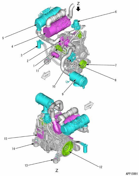
1.cooler8.Auto-tensioner
2.KVGT9.Air cleaner
3.Engine oil filter10.Alternator
4.SCR assembly11Starting motor EGR
5.KDOC12Damper
6.KCCV ventilator13Rear engine mount
7. Vibration damper 14Front engine mount 15Engine controller
SPECIFICATIONS OF ENGINE
Type of damper: Wet type
Damper oil: TO30
Quantity of damper oil: 0.65
SYSTEM
Function of engine system
• KVGT (2) is a turbocharger that changes the cross-sectional area of the exhaust passage.
• EGR cooler (1) is a device that cools down the exhaust gas with the coolant
• KDPF (5) is a device that purifies the exhaust gas.
• KCCV ventilator (7) is a mechanism that returns the blowby gas to the intake side after removing the oil from it in order to burn it again. It mainly consists of filters.
Engine control system
Engine
control system diagram
1.Battery disconnect switch11.Starting motor cut-off relay (for PPC lock)
2.Battery12.Starting motor cut-off relay (for personal code)
3.Battery relay13.Fuel control dial
4.Fusible link14Safety relay
5.Fuse box15Starting motor
6.Starting switch16Fuel supply pump
7.Engine shutdown secondary switch17Various sensors
8Engine controller18Machine monitor
9Lock lever19KOMTRAX terminal
10PPC lock switch20Pump controller
Function of engine control system
Mechanism and function of engine starting system
•When starting switch (6) is turned to ON position, engine controller (8) sends a command current to fuel supply pump (16). Accordingly, a fail safe mechanism is provided that is, the engine stops when the electrical system has trouble.
•When starting switch (6) is turned to START position while lock lever (9) is in LOCK position, the starting procedure is supplied to starting motor (15) and the engine starts. If lock lever (9) is in FREE position, starting motor cut-off relay (11) operates to cut off the starting current to starting motor (15) and the engine does not start, that is, a neutral safety mechanism.
•Upon receipt of the engine cut-off command from the eternal source, KOMTRAX terminal (19) sends the signal to machine monitor(18). operates starting motor cut-off relay (12) to cut off the starting current to starting motor (15), thus the engine does not start.
Mechanism and function of engine speed control system
Upon receipt of the throttle signals from fuel control dial (13 ) and pump controller (20), engine controller (8) selects the lower throttle signal and sends the command current to fuel supply pump (16). Fuel supply pump (16) adjust the fuel injection rate to control the engine speed.
Mechanism and function of engine stopping system
When starting switch (6) is turned to OFF position, the current from terminal ACC of starting switch (6) to engine controller (8) is cut off, and the command current to fuel supply pump (16) is also cut off. Fuel supply pump (16) stops supplying fuel, the engine speed decreases, and the engine stops.
Mechanism and function of engine stopping system with engine shutdown secondary switch
When engine shutdown secondary switch (7) is set to the engine stop position, the current from terminal ACC of starting switch (6) to engine controlle r (8) is cut o ff forcibly. The condition becomes the same as when starting switch (6) is turned to OFF position, and the engine stops.
CLICK HERE TO DOWNLOAD THE COMPLETE MANUAL
• Thank you very much for reading the preview of the manual.
• You can download the complete manual from: www.heydownloads.com by clicking the link below
• Please note: If there is no response to CLICKING the link, please download this PDF first and then click on it.
CLICK HERE TO DOWNLOAD THE
Auto-deceleration system
Auto-deceleration system diagram
A.CAN signal
B.Oil pressure sensor signal
C.Oil pressure switch signal
1.Pump controller
2.Engine controller
3.Machine monitor
4.Fuel control dial
5.Fuel supply pump
6.Various sensors
7.Oil pressure switch
Function of auto-deceleration system
D.1st throttle signal
E.Fuel supply pump control signal
F.Various sensor signals
8.Oil pressure sensor
9.Main pump
10Control valve
11PPC lock solenoid valve
12Travel PPC valve
13Gear pump
• When all the control levers are set to NEUTRAL positions while waiting for a dump truck or next work, the engine speed decreases to the control speed automatically to improve the fuel economy and reduce the noise.
• If any control lever is operated, the engine speed returns immediately to the speed set with the fuel control dial.
Operation of auto-deceleration system
A.When all work equipment control levers are in NEUTRAL
B.When work equipment control lever is operated
C.Speed which is set with fuel control dial
D.Engine control speed (approximately 1050 rpm)
E.4 seconds
F.2 seconds or less
G.1 second or less
When control lever is in NEUTRAL
While the engine is running at approximately 1050 rpm or higher speed, when all the control levers are kept in NEUTRAL for 4 seconds or more, engine speed is decreased to approximately 1050 rpm and kept to the engine control speed (approximately 1050 rpm) until any control lever is operated.
When control lever is operated
While the engine speed is kept at the engine control speed (approximately 1050 rpm), when any control lever is operated, the engine speed increases immediately to the fuel control dial set speed.
Engine automatic warm-up system
Engine automatic warm-up system diagram
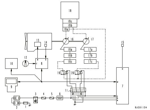
aFront pump PC-EPC valve drive signaldCAN signal
bRear pump PC-EPC valve drive signaleHydraulic oil temperature signal
cSolenoid valve GNDf.1st throttle signal
1.Battery disconnect switch gFuel supply pump control signal
2.BatteryhVarious sensor signals
3.Battery relay 16 Front pump
4.Fusible link 16aServo
5.Fuse box16bLS valve
6.Resistor for PC-EPC valve16cPC valve
7.Pump controller 17Rear pump
8.Engine controller17aServo
9.Machine monitor17bLS valve
10.Air conditioner unit17cPC valve
11.Pump secondary drive switch18 Control valve
12.Fuel control dial18aSelf-pressure reducing valve
13Fuel supply pump18bMerge-divider valve
14Various sensors18cTravel junction valve
15Hydraulic oil temperature sensor19Front pump PC-EPC valve 20Rear pump PC-EPC valve
Function of engine automatic warm-up system
• When the coolant temperature is low after the engine is started, the engine speed is increased automatically to warm up the engine.
• The engine automatic warm up function has 2 kinds; "Heater warm up" and "normal warm up". either of which is used according to the purpose.
The purpose of the heater warm up function is to increase the coolant temperature to improve the effect of the heat.
The purpose of the normal warm up is to heat the engine to prevent damage on the engine caused by low temperature.
Operating conditions 1
Machine specification: Air conditioner specification
Air conditioner: Blower “ON”
Coolant temperature: Below 55 °C
Ambient temperature: Below 5 °C
Manual stationary regeneration: OFF
Soot accumulation: Max. 2 g/ℓ
When any of operating conditions 1 is not satisfied
Heater warm-up disabled (normal warm-up)
When all of operating conditions 1 are satisfied Heater warm-up enabled
Operating conditions 2
(Operates when all of the following conditions are satisfied)
Coolant temperature: Below 30 °C
Engine speed: Max. 1200 rpm
OperationOperation
Coolant temperature: Below 30 °C
Engine speed: 1200rpm
Condition to cancel
(Canceled when any of the following conditions is satisfied)
Automatic
Coolant temperature: Min. 30 °C
Warm-up operation time: Min. 10 minutes
ManualFuel control dial: held at 70% or more of high idle (MAX) for 3 seconds and longer.
Cancellation
Engine Speed: 1300rpm
Condition to cancel
(Canceled when any of the following conditions is satisfied)
Coolant temperature: Min. 60 °C
Ambient temperature: Min. 10 °C
Engine speed: any
Overheat prevention system
Overheat prevention system diagram
aFront pump PC-EPC valve drive signaldCAN signal
bRear pump PC-EPC valve drive signaleHydraulic oil temperature signal
cSolenoid valve GNDf1st throttle signal
1.Battery disconnect switch gFuel supply pump control signal
2.BatteryhVarious sensor signals
3.Battery relay 16aServo
4.Fusible link 16bLS valve
5.Fuse box16cPC valve
6.Resistor for PC-EPC valve17Rear pump
7.Pump controller 17aServo
8.Engine controller17bLS valve
9.Machine monitor17cPC valve
10.Air conditioner unit18Control valve
11.Pump secondary drive switch18aSelf-pressure reducing valve
12.Fuel control dial18bMerge-divider valve
13Fuel supply pump18cTravel junction valve
14Various sensors19Front pump PC-EPC valve
15Hydraulic oil temperature sensor20 Rear pump PC-EPC valve
16Front pump
Function of overheat prevention system
When the coolant temperature or the hydraulic oil temperature increases too high during operation, the pump load is reduced and the engine speed is lowered to prevent overheat and protect the engine and hydraulic components.
Operation conditionOperation and remedy
Working mode: Travel
Hydraulic oil temperature Min. 95°C
Working mode: P, E, ATT-P , or ATT-E mode
Coolant temperature Min. 100°C or Hydraulic oil temperature Min. 100°C →
Engine speed: Kept as it is Pump discharged volume: Throttled
Working mode: P, E, ATT-P , or ATT-E mode
Coolant temperature Min. 102°C or Hydraulic oil temperature Min. 102°C →
Engine speed: Kept as it is Pump discharged volume: Throttled
• Pump absorption torque is lowered and engine load is reduced according to the torque control signal.
Engine speed: Kept as it is.
Pump discharged volume: Throttled
• Pump absorption torque is lowered and engine load is reduced according to the torque control signal.
→
Condition to cancel
Hydraulic oil temperature Below 93°C
• When above condition is satisfied, state before operation is restored (automatic restoration).
Coolant temperature Below 100°C
Hydraulic oil temperature Below 100°C
• When above condition is satisfied, state before operation is restored (automatic restoration).
Coolant temperature Below 102°C
Hydraulic oil temperature Below 102°C
→
Working mode: B mode
Coolant temperature Min. 102°C or Hydraulic oil temperature Min. 102°C
→
Working mode: All modes
Coolant temperature Min. 105°C or Hydraulic oil temperature Min. 105°C
→
Engine speed: Kept as it is Pump discharged volume: Throttled Alarm monitor: lights up
→
• When above condition is satisfied, state before operation is restored (automatic restoration).
Coolant temperature Below 102°C
Hydraulic oil temperature Below 102°C
• When above condition is satisfied, state before operation is restored (automatic restoration).
Coolant temperature Below 105°C
Hydraulic oil temperature Below 105°C
Engine speed: Low idle Alarm monitor: Lights up Alarm buzzer: Sounds
→
Fuel control dial: Return to Low idle (MIN) position.
• When above condition is satisfied, state before operation is restored (automatic restoration).
Turbocharger protection system
Turbocharger protection system diagram
aFront pump PC-EPC valve drive signaldCAN signal
bRear pump PC-EPC valve drive signaleHydraulic oil temperature signal
cSolenoid valve GNDf1st throttle signal
1.Battery disconnect switch gFuel supply pump control signal
2.BatteryhVarious sensor signals
3.Battery relay 16aServo
4.Fusible link 16bLS valve
5.Fuse box16cPC valve
6.Resistor for PC-EPC valve17Rear pump
7.Pump controller 17aServo
8.Engine controller17bLS valve
9.Machine monitor17cPC valve
10.Air conditioner unit18Control valve
11.Pump secondary drive switch18aSelf-pressure reducing valve
12.Fuel control dial18bMerge-divider valve
13Fuel supply pump18cTravel junction valve
14Various sensors19Front pump PC-EPC valve
15Hydraulic oil temperature sensor20 Rear pump PC-EPC valve
16Front pump
Function of turbocharger protection system
This function limits the engine speed to prevent seizure of the turbocharger when the engine speed is increased suddenly just after the engine is started.
Operating conditionOperation
Engine oil pressure: Below 50 kPa {0.51 kgf/cm2}
A.Starting of engine
Protection of turbocharger (see following figure)
B.Turbocharger protection time (approximately 0 to 20 seconds)
C.Modulation time (approximately 1 second)
D.500 rpm
E.Approximately 1050 rpm
F.1650 rpm (*1)
(*1).Working mode: P mode
Fuel control dial: High idle (MAX) position
Travel lever: Fine control
Automatic idle stop system
Automatic idle stop system diagram
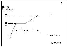
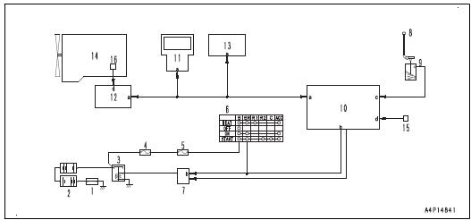
A.CAN signal
C.Lock lever signal B.BR signal D.Various sensor signals
1Battery disconnect switch
9PPC lock switch
2Battery10Pump controller
3Battery relay 11Machine monitor
4Fusible link 12Engine controller
5Fuse box 13KOMTRAX terminal
6Starting switch 14Engine
7Relay15Hydraulic oil temperature sensor
8Lock lever 16Coolant temperature sensor
Function of automatic idle stop system
• When the auto idle stop function is enabled and the conditions for operation are satisfied, the engine is stopped after the set time.
• Engine stops by auto idle stop function when engine controller judges the applicable condition and stops the engine.
• When the engine is stopped by the auto idle stop function while it is running at high speed, a message to turn ON the auto-deceleration function is displayed on the machine monitor, and the auto-deceleration function is set to ON.
• The operating time of the auto idle stop function can be set by user menu or service menu on the machine monitor.
Operating conditions of the auto idle stop system
The auto idle stop function is actuated when all of the following conditions are met at the same time.
• Engine is running
• Lock lever is in "LOCK" position.
• Working mode is “P”, “E”, “ATT/P”, “ATT/E”, or “B”. (Disabled when working mode is “L” or “Arm crane”).
• Engine automatic warm-up function of "Normal warm-up" mode is not being operated.
• Engine coolant is not overheating (below 102 °C).
• Hydraulic oil is not overheating (below 102 °C)
• Auto idle stop time on machine monitor has not been reset.
• Machine monitor is not set in service mode. (*1)
• None of following failure codes is occurring.
*1: See "Setting time".
Relevant failure codes are as follows
Failure codeFailure (displayed on screen)
B@BCNSEng Water Overheat
B@HANSHyd Oil Overheat
CA144Coolant Temperature Sensor High Error
CA145Coolant Temperature Sensor Low Error
D8AQKRCAN 2 Defective Communication (KOMTRAX)
DA2RKRController Area Network 1 Defective Communication (Pump Controller)
DA2QKRController Area Network 2 Defective Communication (Pump Controller)
DAFQKRCAN 2 Defective Communication (Monitor)
DB2RKRCAN 1 Defective Communication (Engine Controller)
DB2QKRCAN 2 Defective Communication (Engine Controller)
DGH2KAHydraulic Oil Temperature Sensor Open Circuit
DGH2KBHydraulic Oil Temperature Sensor Ground Fault
Setting time
Set a time for the auto idle stop function according to the following items.
For setting of each menu, see TESTING AND ADJUSTING
Auto Idle Stop Time Fixing (service menu)
SettingContents of setting
VariableIn auto idle stop time setting menu, operator can select OFF or minimum set time in auto idle stop setting to maximum time of 60 minutes. (Default)
OFFThe auto idle stop function does not operate, and the auto idle stop time setting menu is not displayed.
Fix to x minutes.In auto idle stop time setting menu, operator can select set time in auto idle stop setting to X minutes (set time at left). (Cannot select OFF)
Auto Idle Stop Time Fixing (user menu)
SettingContents of setting
OFFAuto idle stop function does not operate. (Default) y minutes.Stop the engine at Y minutes (set time at left) after setting the lock lever to LOCK position.
NOTICE
When "Fix X min." is selected in the Auto idle stop time fixing menu, the screen changes to the operator screen automatically and the auto idle stop function operates 60 minutes after the lock lever is set to LOCK position, even if the Service menu is being used.
Before performing work with the Service menu, check the set value of the auto idle stop function.
Abrupt engine stop is detected
•The failure code for a detected abrupt engine stop is sent when the engine is stopped by the auto idle stop function when the auto-deceleration function is OFF and the fuel control dial is at a position larger than MIN.
•The failure code is recorded i n the mechanical system abnormality record.
•If an abrupt engine stop is detect
The failure code displayed at an abrupt engine stop varies with the number of occurrence, and the message displayed on the machine monitor varies according to the failure code.
Action levelFailure codeFailure (displayed on screen
L00A900N6Abrupt Engine Stop by Auto Idling Stop 1
L01A900NYAbrupt Engine Stop by Auto Idling Stop 2
L03A900FRAbrupt Engine Stop by Auto Idling Stop 3
•When failure code “A900FR” of action level “L03” is sent, the turbocharger assembly must be replaced since the durability of the engine may decrease.
•After replacing the turbocharger assembly, reset the number of occurrence by using “Reset number of abrupt stops by auto idle stop” in “Inspection” on the service menu.
REMARK
If the number of occurrence is not reset by using “Reset number of abrupt stops by auto idle stop”, failure code “A900FR” is sent again next time and after. Accordingly, be sure to reset after replacing the turbocharger assembly.
Component parts of engine system
VGT
Abbreviation for Variable Geometry Turbocharger
Structure of VGT
REMARK
• Four cylinder engine is shown in this item
• The shape is subject to machine models.
General view, sectional view
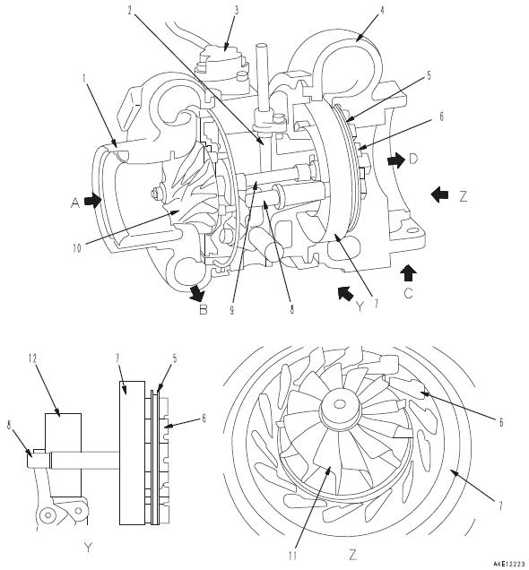
A.Intake air inletC.Exhaust inlet
B.Intake air outletD.Exhaust outlet
1Blower housing7Nozzle ring
2VGT speed sensor8Push rod
3Hydraulic actuator9Shaft
4Turbine housing10Blower impeller
5Plate11Turbine impeller
6Vane12Piston
Function of VGT
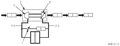
C.Blower impellerT.Turbine impeller
1Air cleaner5SCR assembly
2VGT6EGR cooler
3KDPF7EGR valve
4AdBlue/DEF mixing tube (*1)
*1: This may not be installed on some machine models and specifications.
• The exhaust gas regulations are applied to the exhaust gas from the engine running at low speed, as well as at high speed. To meet this, the EGR ratio is improved. (EGR ratio = Ratio of amount of EGR to amount of fresh suction air)
• To attain high EGR ratio, turbine inlet pressure (P3) must be set higher than boost pressure (P2) (P3 > P2). For this reason, the variable turbocharger (VGT) is employed, in which the exhaust gas pressure acting on turbine impeller (T) is adjustable.
Also, since the boost pressure increases more quickly, generation of particulate caused by lack of oxygen during lowspeed operation (rotation) is reduced.
• The shaft joined to turbine impeller (T) drives blower impeller (C) and sends much air to the cylinder for combustion.
’If VGT (2) sends more air, the fuel injection rate can be increased, thus the engine output is increased. In addition, the air cooled by after-cooler becomes dense, that is, more oxygen is supplied, thus the fuel injection rate can be increased and the engine output is increased.
NOTICE
Adequate amount of clean high quality oil is required to maintain VGT performance. Be sure to use Komatsu genuine high quality oil. Follow the procedures in the Operation and Maintenance Manual when replacing oil or oil filter.
REMARK
It sounds like air is leaking from VGT or a boost pipe, but it is not abnormal.
CLICK HERE TO DOWNLOAD THE COMPLETE MANUAL
• Thank you very much for reading the preview of the manual.
• You can download the complete manual from: www.heydownloads.com by clicking the link below
• Please note: If there is no response to CLICKING the link, please download this PDF first and then click on it.
CLICK HERE TO DOWNLOAD THE
Operation of VGT
REMARK
Six cylinder engine is shown in this figure.
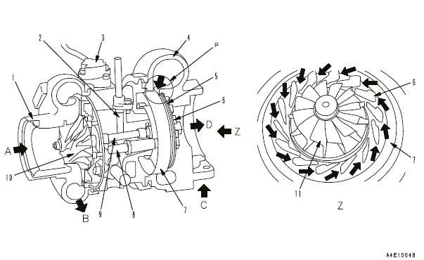
1.The exhaust gas enters (C) of turbine housing (4) and flows out through portion (P) and (D). Portion (P) is surrounded by plate (5) fixed to turbine housing, nozzle ring (7), and vanes (6).
The area of its passage is changed by sliding push rod (8) to the right or left.
2.Hydraulic actuator (3) moves piston in the actuator up and down with the hydraulic pressure controlled by EPC valve installed to the front cover, and slides push rod (8) to the right and left.
3.The exhaust gas flowing through vanes (6) rotates blower impeller (10) through shaft (9) joined to turbine impeller (11) As the result, the blower impeller works as a compressor, and the intake air entering through (A) is compressed and discharge through (B).
4.When the exhaust gas pressure at inlet (C) of turbine housing (4) is low (engine speed is in low range), push rod (8) slides to the right and narrows portion (P).
5.The exhaust gas acting on turbine impeller (11) increases, the turbocharger speed increases, and more air (oxygen) is taken in.
VGT speed sensor (2) detects the rotation of the turbocharger.
When nozzle ring is "closed"
1.During low speed operation (rotation), exhaust gas inlet passage (P) is narrow (L1). (It is not fully closed, however.)
2.If the turbine inlet pressure increases while the nozzle ring is closed, the turbine inflow speed increases, and accordingly the turbocharger speed increases.
When nozzle ring is "open"
1.During high speed operation (rotation), exhaust gas inlet passage (P) is wide (L2).
2.As the engine speed increases and the turbine inlet pressure (exhaust gas pressure) increases exhaust gas inlet passage (P) is widened (L2) so that the exhaust gas acts on turbine impeller (11) efficiently.
REMARK
•Nozzle ring (7), vanes (6), and push rod (8) are made in one unit, and it slides only and does not rotate.
•Hydraulic actuator (3) is equipped with VGT position sensor. VGT position sensor is calibrated together with the variable mechanism of VGT and the result is written in the memory in VGT position sensor. Accordingly, if any of hydraulic actuator (3), VGT position sensor, and VGT unit fails, whole VGT must be replaced.
Operation of hydraulic actuator
The shape is subject to machine models.
1.Hydraulic actuator (1) is controlled by EPC valve (3) installed to EGR valve (2) and driven hydraulically.
2.The hydraulic pressure supplied by boost oil pump (4) is used for this purpose.
3.The position of hydraulic actuator (1) is fed back to engine controller by the signals from VGT position sensor.
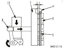
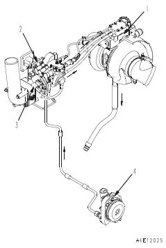
EGR system
EGR
Abbreviation for Exhaust Gas Recirculation
Structure of EGR valve REMARK
•Six cylinder engine is shown in this item.
•The shape is subject to machine models.
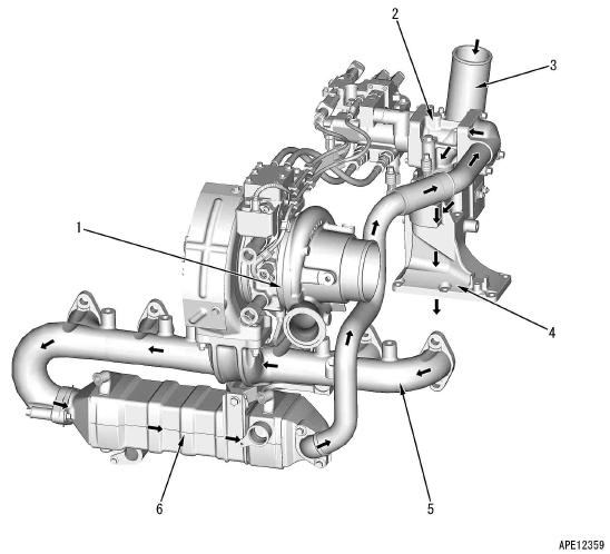
1.VGT4Intake connector
2EGR valve5Exhaust manifold
3Intake pipe6EGR cooler
Function of EGR System
•EGR valve (hydraulically driven type) (2) controls the gas flowing from the exhaust section to the intake section. Since the exhaust pressure is higher than the boost pressure, the exhaust gas flows to the intake side.
•EGR cooler (6) cools down the exhaust gas. Engine coolant is used for cooling.
•It controls EGR circuit on the basis of the information from the sensors installed to various parts so that clean exhaust gas is always discharged to obtain EGR ratio corresponding to the operating condition. (EGR ratio means the ratio of EGR gas contained in the intake gas.)
•It monitors EGR circuit for troubleshooting with sensor installed to each part to prevent a serious failure from occurring.
Circuit Diagram of EGR system
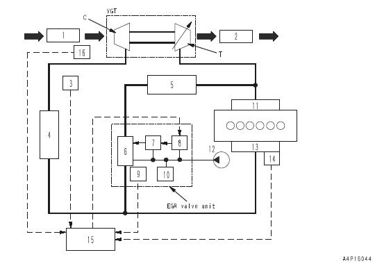
CBlower impellerTTurbine impeller
1Air Cleaner10EGR valve lift sensor
2KDPF11EPC valve (for VGT)
3SCR assembly12Exhaust manifold
4Ambient pressure sensor13Engine boost oil pump
5Aftercooler14Intake manifold
6EGR cooler15Charge (boost) pressure and temperature sensor
7EGR valve16Engine controller
8Hydraulic actuator (power piston)17Mass air flow and temperatu re sensor
9EPC valve (for EGR valve)
OPERATION OF EGR SYSTEM
1.The engine controller outputs signals in order to open EGR valve (7) most properly in accordance with the engine load, so that both of the clean exhausting gas and low fuel con-
sumption can be achieved.
2.When EGR valve (7) opens, a part of the exhaust gas (EGR gas) flows from exhaust manifold (12) into EGR cooler (6) through the EGR piping.
3.The exhaust gas cooled by EGR cooler (6) flows through EGR valve (7) and mixes with the intake air in the intake connector, and then flows in intake manifold (14).
EGR valve
EGR
Abbreviation for Exhaust Gas Recirculation
Structure of EGR valve
REMARK
The shape is subjected to machine models.
Sectional view
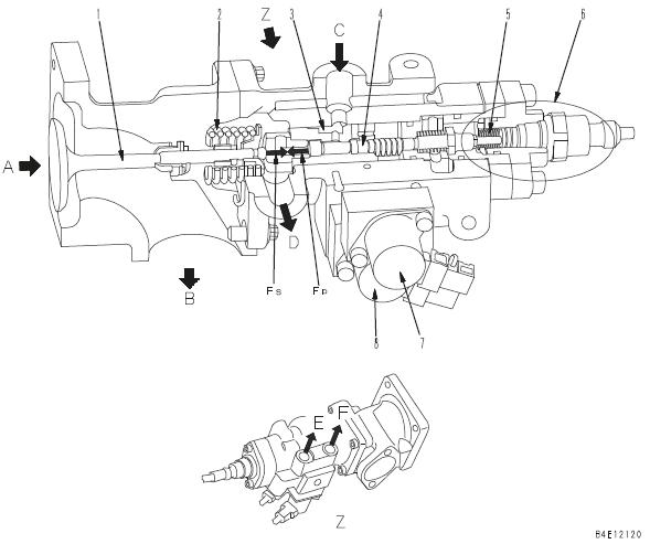
AEGR gas inlet (from EGR cooler)DServo drive oil outlet
BEGR gas outlet (to intake manifold)EKVGT control hydraulic outlet
CServo drive oil inletFKVGT drive pressure outlet
1Valve5Spring
2Spring6EGR valve lift sensor
3Power piston7EPC valve (for EGR)
4Spool8EPC valve (for KVGT)
Structure
•EGR valve consists of the EGR gas flow control mechanism and EPC valve.
•There are 2 EPC valves, one for the EGR control and one for the KVGT control.
Operation of EGR valve
1.The oil from engine boost oil pump enters through port (C) of EGR valve. The control pressure from EPC valve is transmitted to port (E).
2.Spool (4) is moved to the right by the reaction force of spring (5), and EGR valve (1) is closed by the reaction force of spring (2). Accordingly, the exhaust gas from EGR cooler does not flow to the intake side.
3.To open EGR valve (1), the control pressure from EPC valve is transmitted to port (E) first. The position of spool (4) is determined by the balance of the control pressure and spring (5).
4.Since the hydraulic circuit of power piston (3) opens, the oil from the engine boost oil pump flows through port (C) and pushes power piston (3) to the left.
5.The oil from the engine boost oil pump acts on power piston (3) and generates force (Fp).
6.When force (Fp) increases more than reaction force (Fs) of spring (2), EGR valve (1) opens and the exhaust gas flows to the intake side.
7.Since the hydraulic circuit to spool (4) is closed by movement of power piston (3), power piston (3) is stopped at a position determined by spool (4).
8.The engine controller controls the valve position by controlling the spool position with the control pressure of EPC valve.
9.Since the servo mechanism is applied, external force applied to valve (1) does not act on spool (4) which is in contact with power piston (3).
10.EGR valve lift sensor senses the displacement of spool (4).
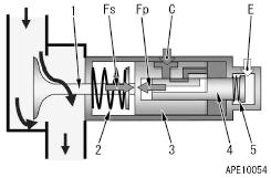
EGR cooler
EGR
Abbreviation for Exhaust Gas Recirculation
Structure of EGR cooler REMARK
The shape is subjected to machine models.
General view and sectional view
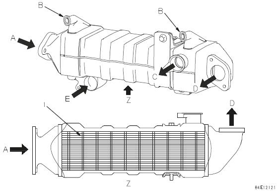
AEGR gas inletDEGR gas outlet
BAir ventECoolant inlet
CCoolant outlet
1Flat tube
Detailed drawing of flat tube
1: Flat tube
2: Inner fin
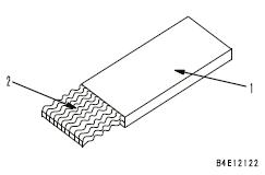
Operation of EGR cooler
1.EGR gas enters through (A) and flows through flat tubes (1) (11 pieces).
2.Coolant enters through (E), flows outside of flat tubes (1) in the case, and goes out through (C).
3.Flat tube (1) has inner fins (2), thus EGR gas is cooled efficiently and discharged through EGR gas outlet (D).
KCCV system
KCCV
Abbreviation for KOMATSU Closed Crankcase Ventilation
Layout drawing of KCCV system
REMARK
The shape is subjected to machine models.
General view
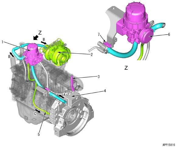
ABlowby gas (from flywheel housing)CEngine oil segregated at the filter (to oil pan)
B Blowby gas from which engine oil is removed (to VGT)
1KCCV ventilator5Check valve
2VGT6CDR valve
3Blowby duct7Crankcase pressure sensor
4Flywheel housing
Function of KCCV system
Function of KCCV system
• In the past, blowby gas (A) was allowed to be released into the atmosphere in the past, but now it is restricted by emission regulations.
• Blowby gas (A) contains ingredients of the engine oil. A filter is installed to KCCV ventilator (1) to remove the engine oil to prevent the following possible problems if it is recirculated to VGT (2) as it is.
•Deterioration of turbocharger and aftercooler performance caused by sticking engine oil
•Abnormal combustion in engine
•Malfunction of each sensor caused by sticking engine oil
Operation of KCCV system
Drawing on the left shows the conventional flow of blowby gas. Drawing on the right shows the flow of blowby gas which is sucked in KCCV ventilator and recirculated.
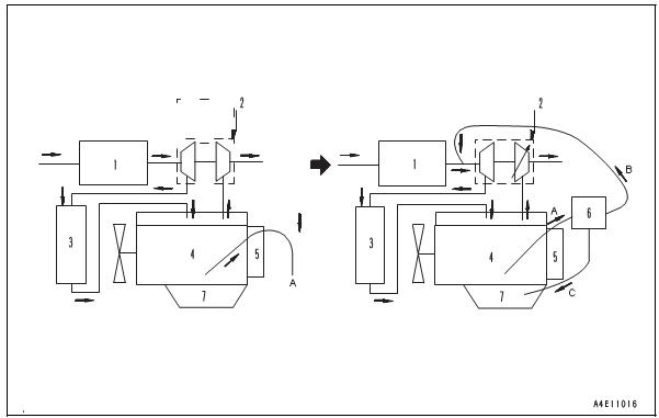
A.Blowby gasCEngine oil
BClean gas
1Air cleaner5Breather
2VGT6KCCV ventilator
3Aftercooler7Engine oil pan
4Cylinder block (crankcase)
1.This system removes engine oil (C) from blowby gas (A) in cylinder block (4) by using the filter in KCCV ventilator (6), and recirculate clean gas (B) to the air intake side of VGT (2)
2.Separated engine oil (C) is drained to engine oil pan (7) through the check valve.
KCCV ventilator
KCCV
Abbreviation for KOMATSU Closed Crankcase Ventilation
Structure of KCCV ventilator
REMARK
The shape is subjected to machine models.
General view and sectional view
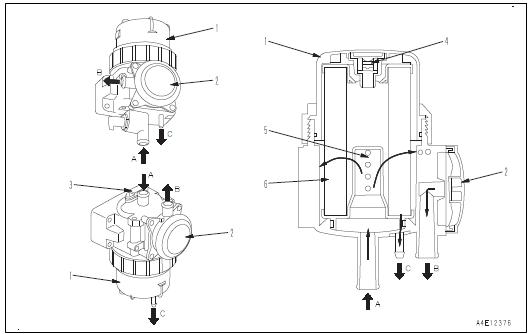
A.Blowby gas inlet (from flywheel housing) COil drain port (to engine oil pan)
BBlowby gas outlet (to VGT intake side)
1Case4Relief valve
2CDR valve5Impactor
3 Crankcase pressure sensor 6Filter
Structure
Filter is classified by the working direction for filter replacement into the top load type (removed upward) and bottom load type (removed downward).
Crankcase pressure sensor is installed to blowby gas inlet piping if it is top load type, and installed to upper part of KCCV ventilator body if it is bottom load type.
Function of KCCV ventilator
• If the blowby gas is returned to the intake side of VGT and crank case pressure becomes negative, the dust may be sucked in through crank seal.
Blowby pressure in crankcase is controlled by CDR valve (2) and crankcase pressure sensor.
CLICK HERE TO DOWNLOAD THE COMPLETE MANUAL
• Thank you very much for reading the preview of the manual.
• You can download the complete manual from: www.heydownloads.com by clicking the link below
• Please note: If there is no response to CLICKING the link, please download this PDF first and then click on it.
CLICK HERE TO DOWNLOAD THE