
METRIC AND INCH (SAE) FASTENERS

Maintenance
PART NO. 524150797 8000 YRM 0231
CLICK HERE TO DOWNLOAD THE COMPLETE MANUAL
• Thank you very much for reading the preview of the manual.
• You can download the complete manual from: www.heydownloads.com by clicking the link below

• Please note: If there is no response to CLICKING the link, please download this PDF first and then click on it.
CLICK HERE TO DOWNLOAD THE
COMPLETE MANUAL
SAFETY PRECAUTIONS MAINTENANCE
AND REPAIR
• The Service Manuals are updated on a regular basis, but may not reflect recent design changes to the product. Updated technical service information may be available from your local authorized Yale® dealer. Service Manuals provide general guidelines for maintenance and service and are intended for use by trained and experienced technicians. Failure to properly maintain equipment or to follow instructions contained in the Service Manual could result in damage to the products, personal injury, property damage or death.
• When lifting parts or assemblies, make sure all slings, chains, or cables are correctly fastened, and that the load being lifted is balanced. Make sure the crane, cables, and chains have the capacity to support the weight of the load.
•Do not lift heavy parts by hand, use a lifting mechanism.
•Wear safety glasses.
• Always use correct blocks to prevent the unit from rolling or falling. See HOW TO PUT THE LIFT TRUCK ON BLOCKS in the Operating Manual or the Periodic Maintenance section.
•Keep the unit clean and the working area clean and orderly.
•Use the correct tools for the job.
•Keep the tools clean and in good condition.
• Always use YALE ® APPROVED parts when making repairs. Replacement parts must meet or exceed the specifications of the original equipment manufacturer.
• Make sure all nuts, bolts, snap rings, and other fastening devices are removed before using force to remove parts.
• Always fasten a DO NOT OPERATE tag to the controls of the unit when making repairs, or if the unit needs repairs.
•Be sure to follow the WARNING and CAUTION notes in the instructions.
• Gasoline, Liquid Petroleum Gas (LPG), Compressed Natural Gas (CNG), and Diesel fuel are flammable. Be sure to follow the necessary safety precautions when handling these fuels and when working on these fuel systems.
• Batteries generate flammable gas when they are being charged. Keep fire and sparks away from the area. Make sure the area is well ventilated.
NOTE: The following symbols and words indicate safety information in this manual:
WARNING
Indicates a hazardous situation which, if not avoided, could result in death or serious injury.
CAUTION
Indicates a hazardous situation which, if not avoided, could result in minor or moderate injury and property damage.
On the lift truck, the WARNING symbol and word are on orange background. The CAUTION symbol and word are on yellow background.
WARNING
Installing improper electrical accessories or installing an electrical accessory incorrectly can increase the risk of equipment damage, personal injury and fire. DO NOT install electrical accessories to the truck unless you have been trained and authorized to do so. Personnel installing the electrical accessories must document the changes made to the truck. DO NOT install accessories which affect the truck’s compliance with standard EN 1175:2020.
WARNING
California Proposition 65 - Operating, servicing and maintaining a powered industrial truck can expose you to chemicals including engine exhaust, carbon monoxide, phthalates, and lead, which are known to the State of California to cause cancer and birth defects or other reproductive harm. For more information, go to www.P65Warnings.ca.gov.
©2023 Yale Materials Handling Corp. TABLE OF CONTENTS General....................................................................................................................................................................1 Threaded Fasteners.............................................................................................................................................1 Nomenclature, Threads........................................................................................................................................1 Strength Identification...........................................................................................................................................2 Cotter (Split) Pins..................................................................................................................................................3 Fastener Torque Tables........................................................................................................................................8 Conversion Table................................................................................................................................................10 Table of Contents i
General
THREADED FASTENERS
Threaded fasteners, like bolts, nuts, cap screws, and studs, are made to specifications that describe the mechanical strength and hardness of the fastener. A fastener used in a design application is selected according to its specifications. Yale® Company buys parts from many countries. Parts that are purchased must be to Yale® Company standards. There are several standards used by these countries in the manufacture of threaded fasteners. Many of these fasteners are similar, but cannot be used as a direct replacement. To make sure that you have the correct fastener, order fasteners and parts through the Yale® Parts Depot.
Service persons must use replacement fasteners that have the same specifications. Fasteners made to each specification have identification marks for that specification. This specification is commonly called "Grade" for SAE standards and "property class" for metric standards. This section describes the identification of some common fasteners.
The metric system used by Yale® Company is described as SI (Le Systeme d'Unites or the International System of units, also called SI in all languages). The SI System of measurement is described in ISO Standard 1000, 1973. A conversion table of common measurements is shown in Table 7.
NOMENCLATURE, THREADS
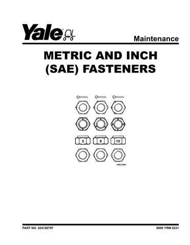
The thread design is specified by a series of numbers and letters for inch and metric fasteners. See Figure 1.
The diameter of the shank of the fastener is shown first in the series [M12 = 12 mm, M20 = 20 mm (1/2 = 1/2 in., 3/4 = 3/4 in.)].
The number of threads per inch is normally not shown for inch nomenclature and only the UNC (Unified National Coarse) or UNF (Unified National Fine) is shown. This number of threads per inch is not shown because a UNC or UNF fastener has a standard number of threads per inch for a specific diameter. Metric fasteners show the number of threads per millimeter.
The length of the shank is often indicated as part of the description of a fastener. This length is shown in inches for inch fasteners and in millimeters for metric fasteners.
A cap screw will have the following description:
Metric Inch
M12 × 1.75 × 50 1/2 × 13 UNC × 1-1/2
A B C A B C D
A = Thread Size A = Shank Diameter
B = Pitch
C = Length
B = Number of Threads Per Unit of Length
C = type of Thread
D = Shank Length
8000 YRM 0231 General 1
Figure 1. Thread Design
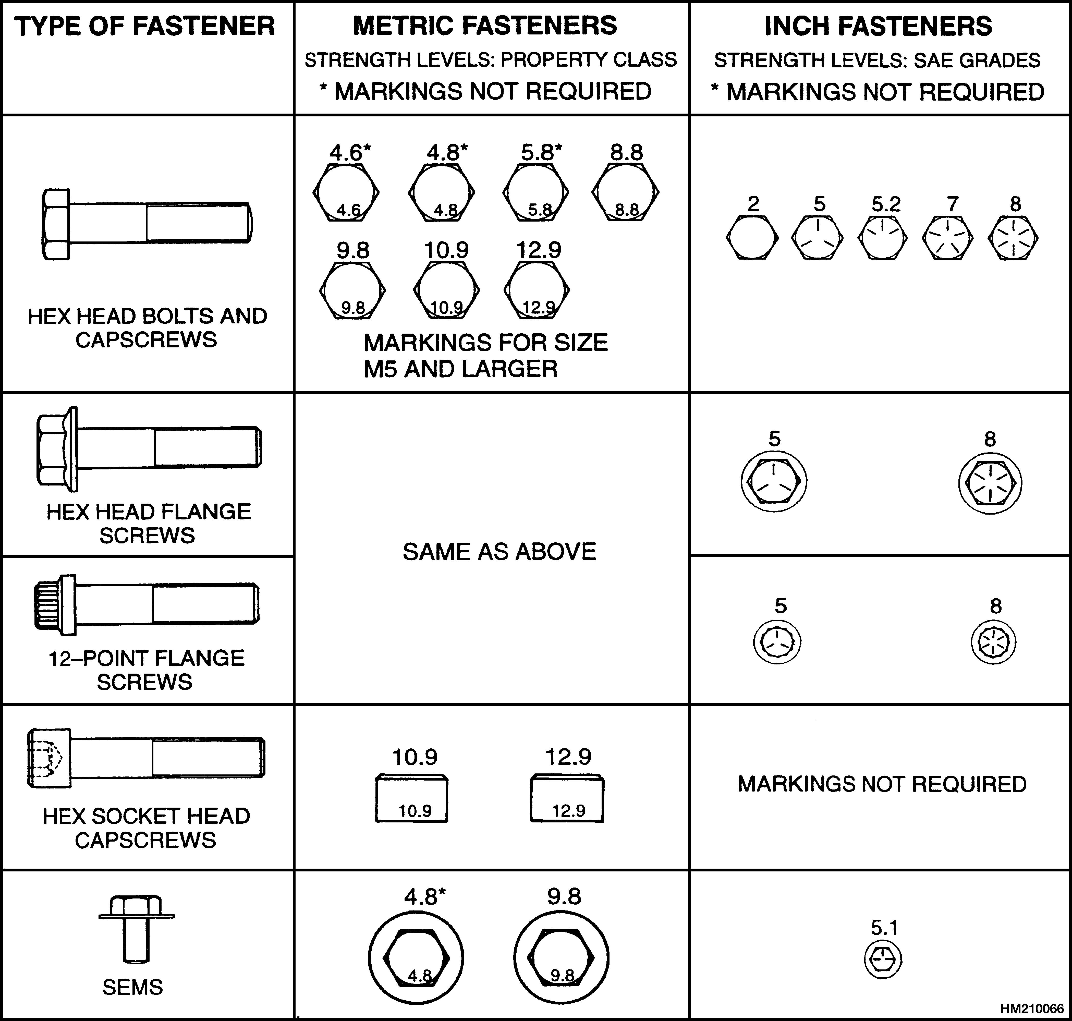
STRENGTH IDENTIFICATION
CAUTION
When fasteners must be replaced, the new fasteners must be of the same strength or greater than the original fasteners. The new fasteners must also be the correct size.
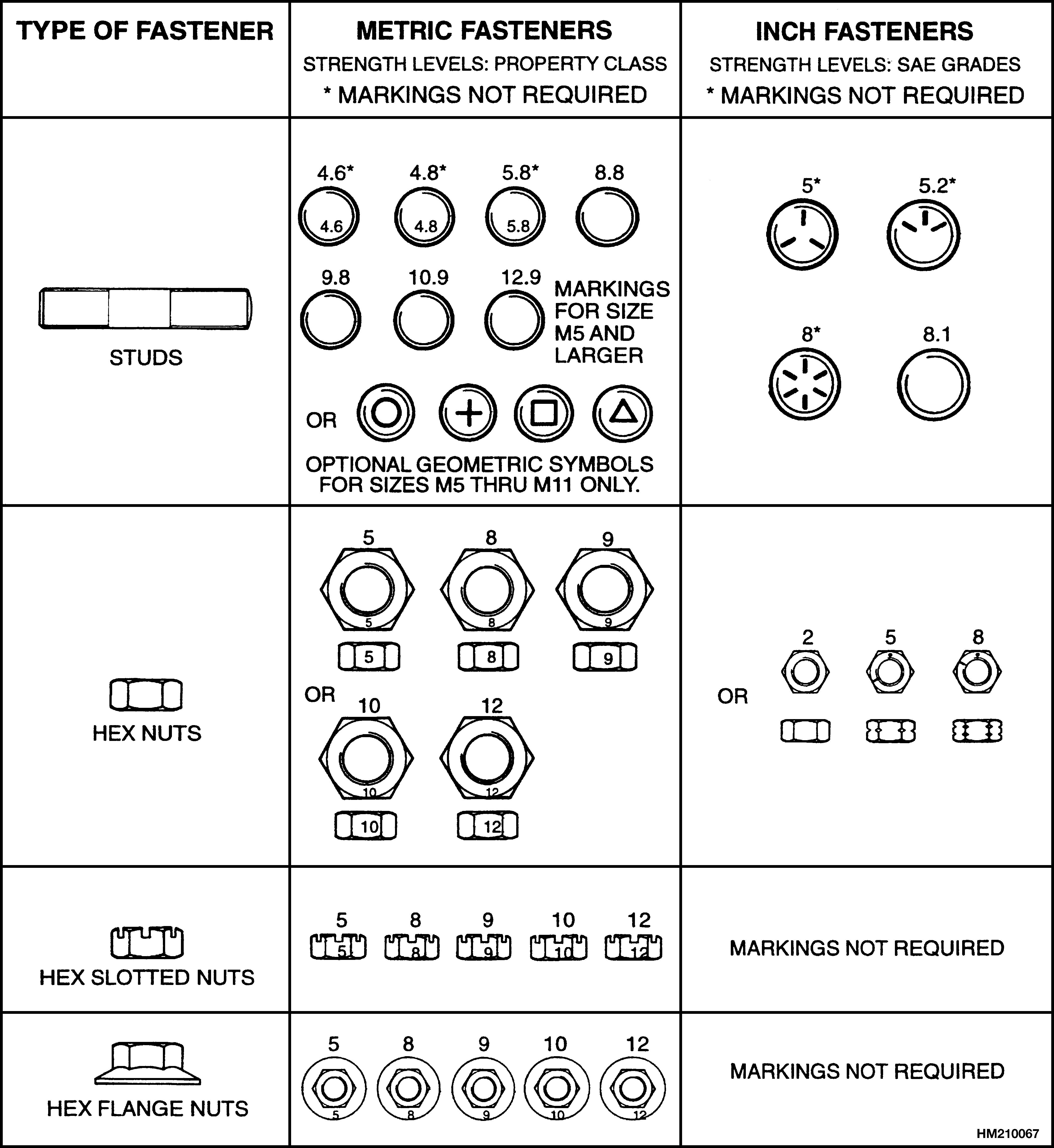
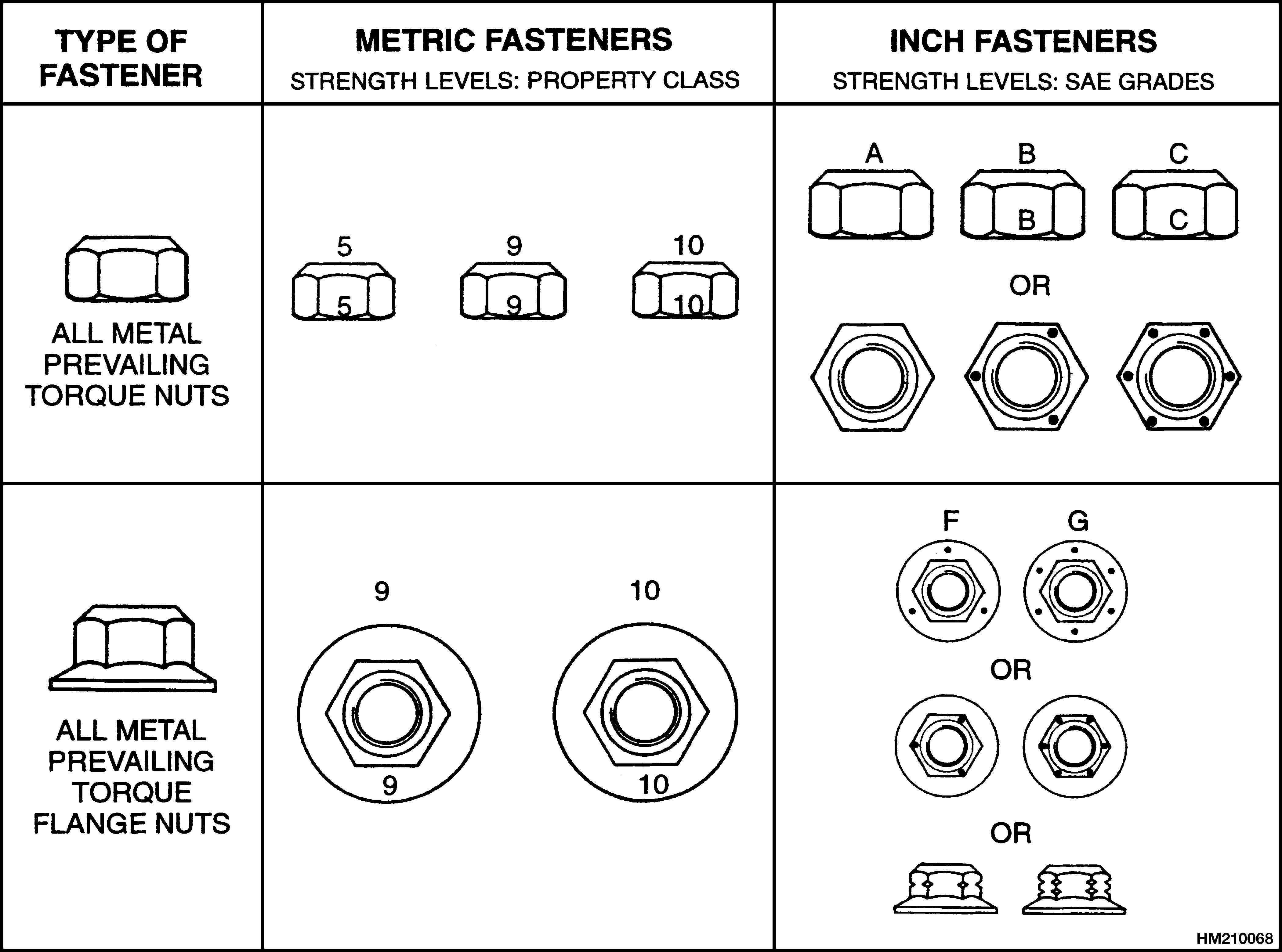
NOTE: Identification marks are according to bolt strength. The higher the number or the increase in the number of marks indicates increased bolt strength.
The most common property classes for metric fasteners are 8.8 and 10.9. The property class is marked with a number on the head of the cap screw or on a nut. Property classes less than 8.8 are often not marked. Grades for inch bolts go from 2 to 8. Grade 2 fasteners normally do not have any marks. The following tables show the marks that identify the grades and property classes for different fasteners.
General 8000 YRM 0231 2
COTTER (SPLIT) PINS
Cotter (split) pins are used in many applications on your forklift. They are typically used to retain parts such as pins and nuts. Cotter (split) pins are typically not used as load-bearing members. Service personnel must use new cotter (split) pins. Do not reuse a cotter (split) pin. Replacement cotter (split) pin must be of the correct size. See Table 8.
The legs of a cotter (split) pin are bent for the following reasons:
• To retain the cotter (split) pin in the part
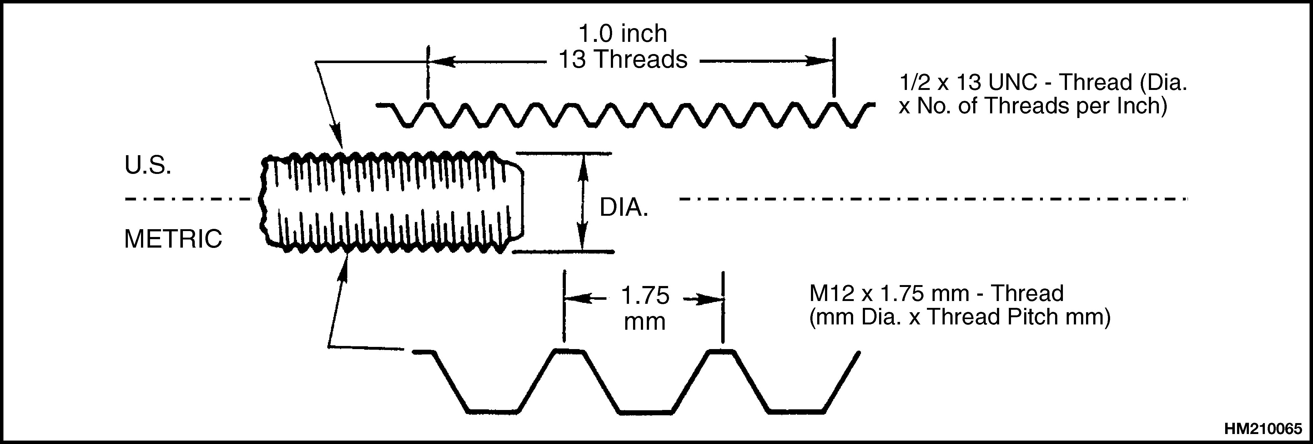
• To provide clearance between the cotter pin legs and other parts or members. One or both cotter (split) pin legs must be bent to provide a minimum 90° angle between the legs. See Figure 2.
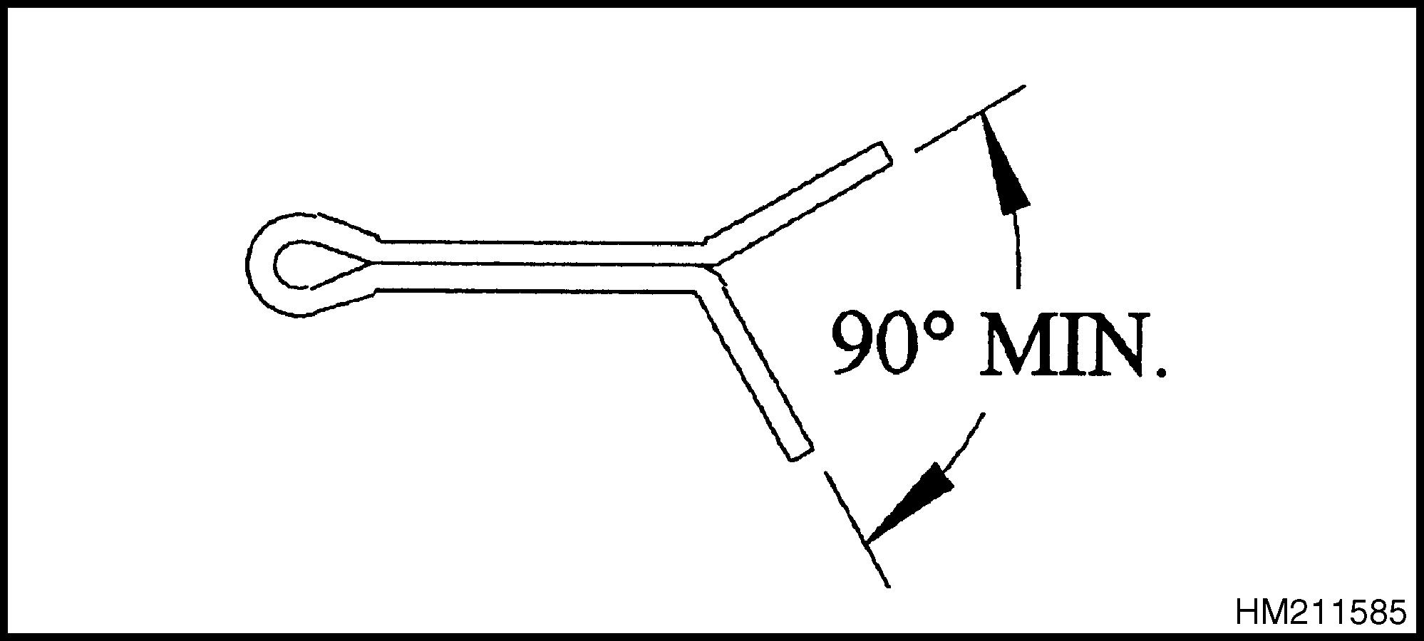
Unless otherwise specified, the legs of chain anchor cotter (split) pins are to be bent against the pin. See Figure 3.
 Figure 2. Minimum Angle Between Cotter Pin Legs
1.COTTER PIN
Figure 2. Minimum Angle Between Cotter Pin Legs
1.COTTER PIN
8000 YRM 0231 General 3
Figure 3. Cotter (Split) Pins Used On Mast Chain Anchors
General 8000 YRM 0231 4
Table 1. Bolts and Screws
CLICK HERE TO DOWNLOAD THE COMPLETE MANUAL
• Thank you very much for reading the preview of the manual.
• You can download the complete manual from: www.heydownloads.com by clicking the link below
• Please note: If there is no response to CLICKING the link, please download this PDF first and then click on it.
CLICK HERE TO DOWNLOAD THE
COMPLETE MANUAL
8000 YRM 0231 General 5
Table 2. Studs and Nuts
General 8000 YRM 0231 6
Table 3. Torque Nuts

8000 YRM 0231 General 7
Table 4. Torque Nuts With Nylon Insert
FASTENER TORQUE TABLES
M42 × 4.5 M42 × 3 M45 × 4.5 M45 × 3 M48 × 5
* Unless otherwise specified 1 Approximately equal to Grade 2 2 Approximately equal to Grade 5 3 Approximately equal to Grade 8
and Pitch
* Unless otherwise specified 1 Approximately equal to metric Property Class 5.8 2 Approximately
Table
Values
Metric
Size and Pitch Property Class 5.81 Grade 8.82 Grade 10.93 N•m lbf ft N•m lbf ft N•m lbf ft
M3.5
0.6 M4 × 0.7 M5 × 0.8 M6 × 1 0.62 0.97 1.44 2.91 4.94 0.5 0.7 1.1 2.1 3.6 0.99 1.55 2.30 4.65 7.90 0.7 1.1 2.1 3.6 6 1.34 2.11 3.13 6.33 10.8 1.0 1.6 2.3 4.7 8 M8 × 1.25 M8 × 1 M10 × 1.5 M10 × 1.25 12.0 12.8 23.8 25.1 9 9 18 19 19.2 20.5 38.0 40.1 14 15 28 30 26.1 27.9 52 55 19 21 38 41 M12 × 1.75 M12 × 1.25 M14 × 2 M14 × 1.5 41.4 45.3 66 72 31 33 49 53 66 72 105 115 49 53 77 85 90 98 145 155 66 72 105 115 M16 × 2 M16 × 1.5 M20 × 2.5 M20 × 1.5 105 110 200 225 77 81 150 165 165 175 320 355 122 130 235 260 225 240 435 485 165 175 320 360 M24 × 3 M24 × 2 M27 × 3 M27 × 2 345 375 505 550 255 275 370 405 555 605 810 875 410 445 600 645 755 820 1,100 1,190 560 605 810 880 M30
×
M33
M33 × 2 690 715 765 940 1,030 510 530 565 695 760 1,100 1,140 1,220 1,500 1,640 810 840 900 1,100 1,210 1,500 1,550 1,660 2,040 2,240 1,100 1,140 1,230 1,510 1,660 M36 × 4 M36 × 3 M39 × 4 M39 × 3 1,200 1,280 1,560 1,640 885 945 1,150 1,210 1,930 2,040 2,490 2,630 1,430 1,510 1,840 1,940 2,620 2,780 3,390 3,570 1,940 2,050 2,500 2,640
3 1,930 2,070 2,410 2,580 2,900 3,160 1,430 1,530 1,780 1,910 2,140 2,330 3,080 3,320 3,850 4,120 4,630 5,040 2,280 2,450 2,840 3,040 3,420 3,720 4,200 4,510 5,240 5,610 6,300 6,860 3,100 3,330 3,870 4,140 4,650 5,060
5. Torque
for
Fasteners*
M3 × 0.5
×
× 3.5 M30 × 3 M30
2
× 3.5
M48 ×
Size
Grade 21 Grade 52 Grade 83 lbf ft N•m lbf ft N•m lbf ft N•m 1/4 1/4 20 UNC 28 UNF 4 5 6 6 6 7 9 10 9 10 12 14 5/16 5/16 18 UNC 24 UNF 8 9 11 13 13 14 18 20 18 20 25 28 3/8 3/8 16 UNC 24 UNF 15 17 20 23 23 26 31 36 33 37 44 50 7/16 7/16 14 UNC 20 UNF 24 27 33 36 37 41 50 56 52 58 71 79
Table 6. Torque Values for Inch Fasteners*
equal to metric Property
equal to metric Property Class 10.9 General 8000 YRM 0231 8
Class 8.8 3 Approximately
Table 6. Torque Values for Inch Fasteners* (Continued)
Size and Pitch Grade 21 Grade 52 Grade 83 lbf ft N•m lbf ft N•m lbf ft N•m 1/2 1/2 13 UNC 20 UNF 37 41 50 56 57 85 77 115 80 90 110 120 9/16 9/16 12 UNC 18 UNF 53 59 72 80 82 91 110 125 115 130 155 175 5/8 5/8 11 UNC 18 UNF 73 83 99 110 115 130 155 175 160 180 215 245 3/4 3/4 10 UNC 16 UNF 130 145 175 195 200 225 270 300 280 315 380 425 7/8 7/8 9 UNC 14 UNF 125 140 170 185 320 355 435 480 455 500 615 680 1 1 8 UNC 14 UNF 185 210 255 285 485 540 655 735 680 765 925 1,040 1-1/8 1-1/8 7 UNC 12 UNF 265 300 360 405 595 670 805 905 965 1,080 1,310 1,470 1-1/4 1-1/4 7 UNC 12 UNF 375 415 510 565 840 930 1,140 1,260 1,360 1,500 1,850 2,050 1-3/8 1-3/8 6 UNC 12 UNF 490 560 665 760 1,100 1,250 1,490 1,700 1,780 2,040 2,420 2,760 1-1/2 1-1/2 6 UNC 12 UNF 650 735 885 995 1,460 1,650 1,980 2,230 2,370 2,670 3,210 3,620 * Unless otherwise specified 1 Approximately equal to metric Property Class 5.8 2 Approximately equal to metric Property Class 8.8 3 Approximately equal to metric Property Class 10.9 8000 YRM 0231 General 9
CONVERSION TABLE
Table 7. Conversion Table for Metric and English units
Multiply By To Get
Multiply By To Get
Area
inches 2 (in. 2) × 6.452 = centimeters 2 (cm 2) centimeters 2 (cm 2) × 0.155 = inches 2 (in. 2)
feet 2 (ft 2) × 0.093 = meters 2 (m 2) meters 2 (m 2) × 10.764 = feet 2 (ft 2)
Linear
inches (in.) × 25.4 = millimeters (mm) millimeter (mm) × 0.039 = inches (in.)
feet (ft) × 0.305 = meters (m) meter (m) × 3.281 = feet (ft)
yards (yd) × 0.914 = meters (m) meter (m) × 1.094 = yards (yd) miles (mi) × 1.609 = kilometers (km) kilometer (km) × 0.621 = miles (mi)
ounces (oz) × 28.35 = grams (g)
Mass
grams (g) × 0.035 = ounces (oz) pounds (lb) × 0.454 = kilograms (kg) kilograms (kg) × 2.205 = pounds (lb)
tons (2,000 lb) × 907.18 = kilograms (kg) kilograms (kg) × 0.001 = tons (2,000 lb)
tons (2,000 lb) × 0.907 = metric ton (t) metric ton (t) × 1.102 = tons (2,000 lb)
Power
horsepower (hp) × 0.746 = kilowatts (kW) kilowatts (kW) × 1.34 = horsepower (hp)
Pressure
pounds/in. 2 (psi) × 6.895 = kilopascal (kPa) kilopascals (kPa) × 0.145 = pounds/in. 2 (psi) pounds/in. 2 (psi) × 0.007 = megapascal (MPa) megapascals (MPa) × 145.04 = pounds/in. 2 (psi)
Temperature
(°Fahrenheit−32) × 0.56 = °Celsius (C) (°Celsius × 1.8) +32 = °Fahrenheit
Torque
pound inches (lbf in.) × 0.113 = Newton meter (N•m) Newton meter (N•m) × 8.851 = pound inches (lb f in.)
pound feet (lbf ft) × 1.356 = Newton meter (N•m) Newton meter (N•m) × 0.738 = pound feet (lb f ft)
Velocity
miles/hour (mph) × 1.609 = kilometer/hour (km/h) kilometer/hr (km/h) × 0.621 = miles/hour (mph)
Volume
inches 3 (in. 3) × 16.387 = centimeters 3 (cm 3) centimeters 3 (cm 3) × 0.061 = inches 3 (in. 3) inches 3 (in. 3) × 0.016 = liters (l) liters (l) × 61.024 = inches 3 (in. 3)
quarts, U.S. (qt) × 0.946 = liters (l) liters (l) × 1.057 = quarts, U.S. (qt) quarts, U.S. (qt) × 0.83 = quarts, Imp. (qt) quarts, Imp. (qt) × 1.205 = quarts, U.S. (qt) gallons, U.S. (gal) × 3.785 = liters (l) liters (l) × 0.264 = gallons, U.S. (gal) gallons, U.S. (gal) × 0.83 = gallons, Imp. (gal) gallons, Imp. (gal) × 1.205 = gallons, U.S. (gal) ounces (oz) × 29.57 = milliliters (ml) milliliters (ml) × 0.034 = ounces (oz)
General 8000 YRM 0231 10
1.00 mm (0.031 in.)
mm (0.047 in.)
2.00 mm (0.062 in.)
2.50 mm (0.094 in.)
in.)
mm (0.035 in.)
Table 8. Cotter Pin Dimensional Data
mm (0.091 in.)
(0.120 in.)
in.)
in.) 4.00 mm (0.156 in.) 3.80 mm (0.150 in.)
mm (0.138 in.)
in.) 5.00 mm (0.188 in.)
in.)
mm (0.312 in.)
mm (0.295 in.)
in.)
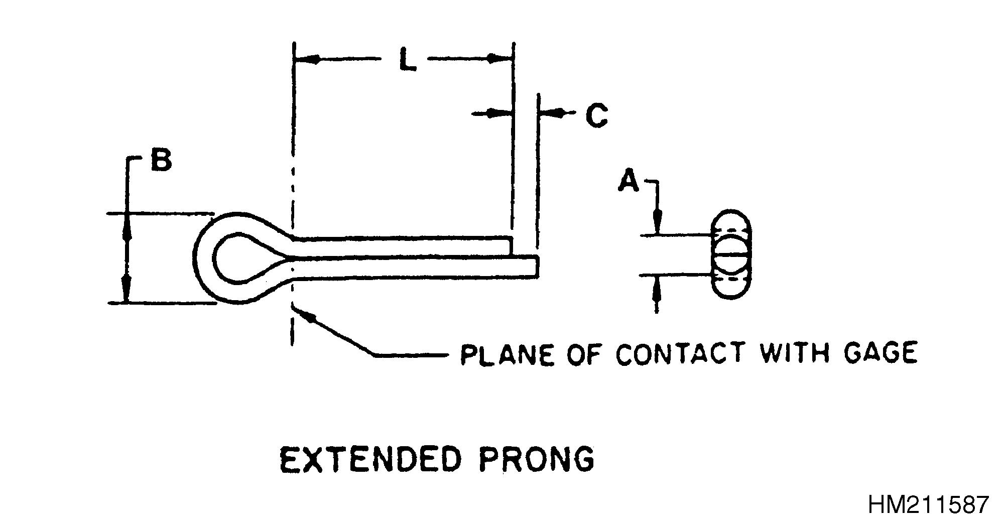
Nominal Size A Shank Diameter A Head Dia. B Length of Extended Prong C Recommended Hole Size max min min max min min max
0.90
0.70
1.50 mm (0.060 in.) 1.52 mm (0.060 in.) 0.25 mm (0.01 in.) 0.91 mm (0.036 in.) 1.37 mm (0.054 in.) 1.60
1.20
0.90 mm (0.035
1.50 mm (0.060
2.54 mm (0.10 in.) 0.51 mm (0.02 in.) 1.50 mm (0.059 in.) 1.78 mm (0.070
mm (0.028 in.)
mm (0.048 in.)
in.)
in.)
in.)
1.50
1.30 mm
2.40 mm
2.54 mm (0.10
0.76 mm (0.03 in.) 1.90 mm (0.075 in.) 2.18 mm (0.086
mm (0.060 in.)
(0.051 in.)
(0.094 in.)
in.)
in.)
2.30
2.10 mm
4.00 mm (0.158
2.54 mm (0.10
1.00 mm (0.04
2.41 mm (0.095
2.95 mm (0.116
3.00 mm
2.70 mm (0.106
5.10 mm (0.201
3.30 mm (0.13
1.52 mm (0.06
3.12 mm (0.123
3.76 mm (0.148
6.50 mm (0.256
4.06 mm (0.16
1.78 mm (0.07
3.94 mm (0.155 in.) 4.55 mm (0.179
4.60 mm (0.181
4.40 mm (0.172
8.00 mm (0.315 in.) 4.06 mm (0.16 in.) 2.03 mm (0.08 in.) 4.93 mm (0.194 in.) 5.33 mm (0.210
6.30 mm (0.250
5.90 mm (0.232 in.) 5.60 mm (0.220 in.) 10.3 mm (0.406 in.) 4.06 mm (0.16 in.) 2.03 mm (0.08
6.22 mm (0.245 in.) 6.96 mm (0.274
in.) 4.06 mm (0.16 in.) 2.03 mm (0.08 in.) 7.85 mm (0.309 in.) 8.28 mm (0.326 in.)
9.50
in.) 8.40 mm (0.329 in.) 16.6 mm (0.654 in.) 6.35 mm (0.25 in.) 4.06 mm (0.16 in.) 9.45 mm (0.372 in.) 9.73 mm (0.383 in.) 13.0 mm (0.500
12.4 mm (0.488
11.9 mm (0.467 in.) 21.7 mm (0.854 in.) 6.35 mm (0.25 in.) 3.05 mm (0.12 in.) 12.62 mm (0.497 in.) 13.21 mm (0.520 in.) 16.0 mm (0.625 in.) 15.4 mm (0.606 in.) 15.0 mm (0.590 in.) 27.0 mm (1.063 in.) 8.89 mm (0.35 in.) 3.05 mm (0.12 in.) 15.80 mm (0.622 in.) 16.28 mm (0.641
8000 YRM 0231 General 11
(0.083 in.)
in.)
in.)
in.)
in.)
in.) 3.20 mm (0.125
in.)
in.)
in.)
in.)
3.50
in.)
in.)
in.)
in.)
in.)
in.)
in.)
in.)
8.00
7.50
7.00 mm (0.275
13.1 mm (0.516
9.50 mm (0.375 in.)
mm (0.374
in.)
in.)
in.)
6.35 mm (0.250 in.)
mm (0.375 in.)
mm (0.280 in.)
mm (0.413 in.)
mm (0.500 in.) 13.5 mm (0.530 in.)
19.05 mm (0.750 in.)
mm (1.000 in.)
mm (1.250 in.)
mm (1.500 in.)
mm (2.000 in.)
mm (0.807 in.)
mm (1.060 in.)
Table 9. Cotter Pin Dimensional Data
mm (0.217 in.)
mm (0.345 in.)
mm (0.453 in.)
mm (0.720 in.)
mm (0.940 in.)
mm (1.610 in.)
mm (2.060 in.)
57.15 mm (2.250 in.) 58.7 mm (2.310 in.)
mm (2.500 in.)
mm (2.560 in.)
mm (2.750 in.) 72.1 mm (2.840 in.)
mm (1.940 in.)
mm (2.170 in.)
in.)
mm (2.690 in.)
76.2 mm (3.000 in.) 81.3 mm (3.200 in.) 74.7 mm (2.940 in.)
88.9 mm (3.500 in.) 91.4 mm (3.600 in.)
mm (3.440 in.)
Nominal Length L Length Range Nominal Size - Part Numbers max min 1.00 mm (0.031 in.) 1.60 mm (0.047 in.) 2.00 mm (0.062 in.) 2.50 mm (0.094 in.) 3.20 mm (0.125 in.)
7.10
5.50
0221870 0221875 9.525
10.5
8.80
0221871 0221876
11.5
0221872 0221877 0015200 0015211 0015221
12.7
18.3
0221873 0221878 0015201 0015212 0015222
26.9
23.9
0221874 0221879 0015202 0015213 0015223 31.75
33.3 mm
29.2 mm (1.150
0015203 0015216 0015224 38.1
40.9
36.6 mm
0015204 0015217 0015225 44.45 mm
46.0 mm (1.810
42.9 mm (1.690
0015205 0015218 0015226
0015206 0015219 0015227
20.5
25.4
(1.310 in.)
in.)
(1.440 in.)
(1.750 in.)
in.)
in.)
50.8
52.3
49.3
55.1
0015220 0056997
65.0
62.0
0221894 0015229
0015230
63.5
mm (2.440
69.85
68.3
0015279
General 8000 YRM 0231 12
87.4
101.6 mm (4.000 in.)
mm (5.000 in.)
mm (6.000 in.)
mm (4.460 in.)
mm (5.060 in.)
mm (3.060 in.)
Table 9. Cotter Pin Dimensional Data (Continued)
6.35 mm (0.250 in.)
mm (0.280 in.)
mm (3.890 in.)
mm (4.870 in.)
mm (138.7 in.)
Table 10. Cotter Pin Dimensional Data
mm (0.217 in.)
9.525 mm (0.375 in.) 10.5 mm (0.413 in.) 8.80 mm (0.345 in.)
12.7 mm (0.500 in.) 13.5 mm (0.530 in.) 11.5 mm (0.453 in.)
19.05 mm (0.750 in.)
mm (0.807 in.)
mm (0.720 in.)
Nominal Length L Length Range Nominal Size
Part Numbers max min 1.00 mm (0.031 in.) 1.60 mm (0.047 in.) 2.00 mm (0.062 in.) 2.50 mm (0.094 in.) 3.20 mm (0.125 in.)
-
113.3
98.8
127.0
128.5
123.7
152.4
153.9
5.460
Nominal
Nominal
max min 4.00 mm (0.156 in.) 5.00 mm (0.188 in.) 6.30 mm (0.250 in.) 8.00 mm (0.312 in.) 9.52 mm (0.375 in.)
Length L Length Range
Size - Part Numbers
7.10
5.50
20.5
18.3
0015232 0015241 8000 YRM 0231 General 13
CLICK HERE TO DOWNLOAD THE COMPLETE MANUAL
• Thank you very much for reading the preview of the manual.
• You can download the complete manual from: www.heydownloads.com by clicking the link below
• Please note: If there is no response to CLICKING the link, please download this PDF first and then click on it.
CLICK HERE TO DOWNLOAD THE
COMPLETE MANUAL
25.4 mm (1.000 in.)
mm (1.250 in.)
38.1 mm (1.500 in.)
44.45 mm (1.750 in.)
50.8 mm (2.000 in.)
mm (2.250 in.)
(2.500 in.)
mm (2.750 in.)
mm (3.000 in.)
mm (1.060 in.)
Table 10. Cotter Pin Dimensional Data (Continued)
(0.940 in.)
mm (1.610 in.)
mm (1.440 in.)
mm (2.060 in.)
mm (1.940 in.)
mm (3.200 in.)
mm (2.940 in.)
88.9 mm (3.500 in.) 91.4 mm (3.600 in.) 87.4 mm (3.440 in.)
mm (4.000 in.)
mm (5.000 in.)
mm (4.460 in.)
mm (5.060 in.)
(3.890 in.)
mm (4.870 in.)
152.4 mm (6.000 in.) 153.9 mm (3.060 in.) 5.460 mm (138.7 in.)
Nominal Length L Length Range Nominal Size - Part Numbers max min 4.00 mm (0.156 in.) 5.00 mm (0.188 in.) 6.30 mm (0.250 in.) 8.00 mm (0.312 in.) 9.52 mm (0.375 in.)
26.9
23.9 mm
0015233 0015242 0015251 0015261 31.75
33.3
29.2 mm
0015234 0015243 0015252 0015262 0221884
40.9
36.6
0015235 0015244 0015253 0015263 0221885
46.0 mm
42.9 mm
0015236 0015245 0015254 0015264 0221886
52.3
49.3
0015237 0015246 0015255 0015265 0015271 57.15
58.7 mm (2.310
55.1 mm (2.170
0015238 0015247 0015256 0221880 0221887 63.5 mm
65.0 mm (2.560
62.0 mm (2.440
0015240 0015248 0015257 0221881 0015273 69.85
72.1
in.) 68.3 mm (2.690 in.) 0015280 0015249 0015258 0221882 0015286 76.2
81.3
74.7
0015283 0015250 0015259 0015267 0015272
mm (1.310 in.)
(1.150 in.)
(1.810 in.)
(1.690 in.)
in.)
in.)
in.)
in.)
mm (2.840
0015239 0015284 0015266 0015274 101.6
113.3
98.8
0015301 0015260 0128754 0015275 127.0
128.5
123.7
0221883 0015277
mm
0221888 General 8000 YRM 0231 14
mm (0.750 in.)
mm (1.00 in.)
mm (1.250 in.)
mm (1.750 in.)
mm (2.000 in.)
Table 11. Cotter Pin Dimensional Data
152.4 mm (6.000 in.) 153.9 mm (3.060 in.) 138.7 mm (5.460 in.)
Nominal Length L Length Range Nominal Size - Part Numbers max min 13.0 mm (0.500 in.) 16.00 mm (0.625 in.) 19.05
20.5
18.3
25.4
26.9
23.9
31.75
33.3
29.2
38.1
40.9
36.6 mm
44.45
46.0
42.9
50.8
52.3
49.3
57.15
58.7 mm
in.) 55.1 mm (2.170
63.5
65.0
62.0
69.85
72.1
68.3 mm (2.690
0221895 76.2
81.3
74.7
0221896 88.9
87.4
101.6
98.8
0015293 0221898 127.0
0015295 0221899
8000 YRM 0231 General 15
mm (0.807 in.)
mm (0.720 in.)
mm (1.060 in.)
mm (0.940 in.)
mm (1.310 in.)
mm (1.150 in.)
mm (1.500 in.)
mm (1.610 in.)
(1.440 in.)
mm (1.810 in.)
mm (1.690 in.) 0221889
mm (2.060 in.)
mm (1.940 in.) 0221890
mm (2.250 in.)
(2.310
in.) 0221891
mm (2.500 in.)
mm (2.560 in.)
mm (2.440 in.) 0221892
mm (2.750 in.)
mm (2.840 in.)
in.) 0221893
mm (3.000 in.)
mm (3.200 in.)
mm (2.940 in.) 0015291
mm (3.500 in.) 91.4 mm (3.600 in.)
mm (3.440 in.) 0015292 0221897
mm (4.000 in.) 113.3 mm (4.460 in.)
mm (3.890 in.)
mm (5.000 in.) 128.5 mm (5.060 in.) 123.7 mm (4.870 in.)
0015297 0221900
8000 YRM 0231 2/23 (9/22)(12/21)(7/21)(5/21)(3/20)
METRIC AND INCH (SAE) FASTENERS
Maintenance
PART NO. 524150797 8000 YRM 0231
SAFETY PRECAUTIONS MAINTENANCE
AND REPAIR
• When lifting parts or assemblies, make sure all slings, chains, or cables are correctly fastened, and that the load being lifted is balanced. Make sure the crane, cables, and chains have the capacity to support the weight of the load.
•Do not lift heavy parts by hand, use a lifting mechanism.
•Wear safety glasses.
• DISCONNECT THE BATTERY CONNECTOR before doing any maintenance or repair on electric lift trucks. Disconnect the battery ground cable on internal combustion lift trucks.
• Always use correct blocks to prevent the unit from rolling or falling. See HOW TO PUT THE LIFT TRUCK ON BLOCKS in the Operating Manual or the Periodic Maintenance section.
•Keep the unit clean and the working area clean and orderly.
•Use the correct tools for the job.
•Keep the tools clean and in good condition.
• Always use APPROVED parts when making repairs. Replacement parts must meet or exceed the specifications of the original equipment manufacturer.
• Make sure all nuts, bolts, snap rings, and other fastening devices are removed before using force to remove parts.
• Always fasten a DO NOT OPERATE tag to the controls of the unit when making repairs, or if the unit needs repairs.
•Be sure to follow the WARNING and CAUTION notes in the instructions.
• Gasoline, Liquid Petroleum Gas (LPG), Compressed Natural Gas (CNG), and Diesel fuel are flammable. Be sure to follow the necessary safety precautions when handling these fuels and when working on these fuel systems.
• Batteries generate flammable gas when they are being charged. Keep fire and sparks away from the area. Make sure the area is well ventilated.
NOTE: The following symbols and words indicate safety information in this manual:
WARNING
Indicates a hazardous situation which, if not avoided, could result in death or serious injury.
CAUTION
Indicates a hazardous situation which, if not avoided, could result in minor or moderate injury and property damage.
On the lift truck, the WARNING symbol and word are on orange background. The CAUTION symbol and word are on yellow background.
©2020 Yale Materials Handling Corp. TABLE OF CONTENTS General....................................................................................................................................................................1 Threaded Fasteners.............................................................................................................................................1 Nomenclature, Threads........................................................................................................................................1 Strength Identification...........................................................................................................................................2 Cotter (Split) Pins..................................................................................................................................................3 Fastener Torque Tables........................................................................................................................................8 Conversion Table................................................................................................................................................10 Table of Contents i
General
THREADED FASTENERS
Threaded fasteners, like bolts, nuts, capscrews, and studs, are made to specifications that describe the mechanical strength and hardness of the fastener. A fastener used in a design application is selected according to its specifications. Yale® Company buys parts from many countries. Parts that are purchased must be to Yale® Company standards. There are several standards used by these countries in the manufacture of threaded fasteners. Many of these fasteners are similar, but cannot be used as a direct replacement. To make sure that you have the correct fastener, order fasteners and parts through the Yale® Parts Depot.
Service persons must use replacement fasteners that have the same specifications. Fasteners made to each specification have identification marks for that specification. This specification is commonly called "Grade" for SAE standards and "property class" for metric standards. This section describes the identification of some common fasteners.
The metric system used by Yale® Company is described as SI (Le Systeme d'Unites or the International System of units, also called SI in all languages). The SI System of measurement is described in ISO Standard 1000, 1973. A conversion table of common measurements is shown in Table 7.
NOMENCLATURE, THREADS
The thread design is specified by a series of numbers and letters for inch and metric fasteners. See Figure 1.
The diameter of the shank of the fastener is shown first in the series [M12 = 12 mm, M20 = 20 mm (1/2 = 1/2 in., 3/4 = 3/4 in.)].
The number of threads per inch is normally not shown for inch nomenclature and only the UNC (Unified National Coarse) or UNF (Unified National Fine) is shown. This number of threads per inch is not shown because a UNC or UNF fastener has a standard number of threads per inch for a specific diameter. Metric fasteners show the number of threads per millimeter.
The length of the shank is often indicated as part of the description of a fastener. This length is shown in inches for inch fasteners and in millimeters for metric fasteners.
A capscrew will have the following description:
Metric Inch
M12 × 1.75 × 50 1/2 × 13 UNC × 1-1/2
A B C
A B C D
A = Thread Size A = Shank Diameter
B = Pitch
C = Length
B = Number of Threads Per Unit of Length
C = type of Thread
D = Shank Length
8000 YRM 0231 General 1
Figure 1. Thread Design
STRENGTH IDENTIFICATION
CAUTION
When fasteners must be replaced, the new fasteners must be of the same strength or greater than the original fasteners. The new fasteners must also be the correct size.
NOTE: Identification marks are according to bolt strength. The higher the number or the increase in the number of marks indicates increased bolt strength.
The most common property classes for metric fasteners are 8.8 and 10.9. The property class is marked with a number on the head of the capscrew or on a nut. Property classes less than 8.8 are often not marked. Grades for inch bolts go from 2 to 8. Grade 2 fasteners normally do not have any marks. The following tables show the marks that identify the grades and property classes for different fasteners.
General 8000 YRM 0231 2
CLICK HERE TO DOWNLOAD THE COMPLETE MANUAL
• Thank you very much for reading the preview of the manual.
• You can download the complete manual from: www.heydownloads.com by clicking the link below
• Please note: If there is no response to CLICKING the link, please download this PDF first and then click on it.
CLICK HERE TO DOWNLOAD THE
COMPLETE MANUAL
COTTER (SPLIT) PINS
Cotter (split) pins are used in many applications on your forklift. They are typically used to retain parts such as pins and nuts. Cotter (split) pins are typically not used as load-bearing members. Service personnel must use new cotter (split) pins. Do not reuse a cotter (split) pin. Replacement cotter (split) pin must be of the correct size. See Table 8.
The legs of a cotter (split) pin are bent for the following reasons:
• To retain the cotter (split) pin in the part
• To provide clearance between the cotter pin legs and other parts or members. One or both cotter (split) pin legs must be bent to provide a minimum 90° angle between the legs. See Figure 2.
Unless otherwise specified, the legs of chain anchor cotter (split) pins are to be bent against the pin. See Figure 3.
Figure 2. Minimum Angle Between Cotter Pin Legs
1.COTTER PIN
8000 YRM 0231 General 3
Figure 3. Cotter (Split) Pins Used On Mast Chain Anchors
General 8000 YRM 0231 4
Table 1. Bolts and Screws
8000 YRM 0231 General 5
Table 2. Studs and Nuts
General 8000 YRM 0231 6
Table 3. Torque Nuts
8000 YRM 0231 General 7
Table 4. Torque Nuts With Nylon Insert
FASTENER TORQUE TABLES
M42 × 4.5 M42 × 3 M45 × 4.5
5,060 * Unless otherwise specified 1 Approximately equal to Grade 2 2 Approximately equal to Grade 5 3 Approximately equal to Grade 8
Table
Metric
Size and Pitch Property Class 5.81 Grade 8.82 Grade 10.93 N•m lbf ft N•m lbf ft N•m lbf ft
M3.5
0.6 M4 × 0.7 M5 × 0.8 M6 × 1 0.62 0.97 1.44 2.91 4.94 0.5 0.7 1.1 2.1 3.6 0.99 1.55 2.30 4.65 7.90 0.7 1.1 2.1 3.6 6 1.34 2.11 3.13 6.33 10.8 1.0 1.6 2.3 4.7 8 M8 × 1.25 M8 × 1 M10 × 1.5 M10 × 1.25 12.0 12.8 23.8 25.1 9 9 18 19 19.2 20.5 38.0 40.1 14 15 28 30 26.1 27.9 52 55 19 21 38 41 M12 × 1.75 M12 × 1.25 M14 × 2 M14 × 1.5 41.4 45.3 66 72 31 33 49 53 66 72 105 115 49 53 77 85 90 98 145 155 66 72 105 115 M16 × 2 M16 × 1.5 M20 × 2.5 M20 × 1.5 105 110 200 225 77 81 150 165 165 175 320 355 122 130 235 260 225 240 435 485 165 175 320 360 M24 × 3 M24 × 2 M27 × 3 M27 × 2 345 375 505 550 255 275 370 405 555 605 810 875 410 445 600 645 755 820 1,100 1,190 560 605 810 880 M30
M33 × 2 690 715 765 940 1,030 510 530 565 695 760 1,100 1,140 1,220 1,500 1,640 810 840 900 1,100 1,210 1,500 1,550 1,660 2,040 2,240 1,100 1,140 1,230 1,510 1,660 M36 × 4 M36 × 3 M39 × 4 M39 × 3 1,200 1,280 1,560 1,640 885 945 1,150 1,210 1,930 2,040 2,490 2,630 1,430 1,510 1,840 1,940 2,620 2,780 3,390 3,570 1,940 2,050 2,500 2,640
5. Torque Values for
Fasteners*
M3 × 0.5
×
× 3.5 M30 × 3 M30 × 2 M33 × 3.5
3 M48 × 5 M48 × 3 1,930 2,070 2,410 2,580 2,900 3,160 1,430 1,530 1,780 1,910 2,140 2,330 3,080 3,320 3,850 4,120 4,630 5,040 2,280 2,450 2,840 3,040 3,420 3,720 4,200 4,510 5,240 5,610 6,300 6,860 3,100 3,330 3,870 4,140 4,650
General 8000 YRM 0231 8
M45 ×
Table 6. Torque Values for Inch Fasteners*
Size and Pitch Grade 21 Grade 52 Grade 83 lbf ft N•m lbf ft N•m lbf ft N•m 1/4 1/4 20 UNC 28 UNF 4 5 6 6 6 7 9 10 9 10 12 14 5/16 5/16 18 UNC 24 UNF 8 9 11 13 13 14 18 20 18 20 25 28 3/8 3/8 16 UNC 24 UNF 15 17 20 23 23 26 31 36 33 37 44 50 7/16 7/16 14 UNC 20 UNF 24 27 33 36 37 41 50 56 52 58 71 79 1/2 1/2 13 UNC 20 UNF 37 41 50 56 57 85 77 115 80 90 110 120 9/16 9/16 12 UNC 18 UNF 53 59 72 80 82 91 110 125 115 130 155 175 5/8 5/8 11 UNC 18 UNF 73 83 99 110 115 130 155 175 160 180 215 245 3/4 3/4 10 UNC 16 UNF 130 145 175 195 200 225 270 300 280 315 380 425 7/8 7/8 9 UNC 14 UNF 125 140 170 185 320 355 435 480 455 500 615 680 1 1 8 UNC 14 UNF 185 210 255 285 485 540 655 735 680 765 925 1,040 1-1/8 1-1/8 7 UNC 12 UNF 265 300 360 405 595 670 805 905 965 1,080 1,310 1,470 1-1/4 1-1/4 7 UNC 12 UNF 375 415 510 565 840 930 1,140 1,260 1,360 1,500 1,850 2,050 1-3/8 1-3/8 6 UNC 12 UNF 490 560 665 760 1,100 1,250 1,490 1,700 1,780 2,040 2,420 2,760 1-1/2 1-1/2 6 UNC 12 UNF 650 735 885 995 1,460 1,650 1,980 2,230 2,370 2,670 3,210 3,620 *
Approximately equal to metric Property
5.8
Approximately equal to metric Property
8.8
Approximately equal to metric Property Class 10.9 8000 YRM 0231 General 9
Unless otherwise specified 1
Class
2
Class
3
CONVERSION TABLE
Table 7. Conversion Table for Metric and English units
Multiply By To Get
Multiply By To Get
Area
inches 2 (in. 2) × 6.452 = centimeters 2 (cm 2) centimeters 2 (cm 2) × 0.155 = inches 2 (in. 2)
feet 2 (ft 2) × 0.093 = meters 2 (m 2) meters 2 (m 2) × 10.764 = feet 2 (ft 2)
Linear
inches (in.) × 25.4 = millimeters (mm) millimeter (mm) × 0.039 = inches (in.)
feet (ft) × 0.305 = meters (m) meter (m) × 3.281 = feet (ft)
yards (yd) × 0.914 = meters (m) meter (m) × 1.094 = yards (yd) miles (mi) × 1.609 = kilometers (km) kilometer (km) × 0.621 = miles (mi)
ounces (oz) × 28.35 = grams (g)
Mass
grams (g) × 0.035 = ounces (oz) pounds (lb) × 0.454 = kilograms (kg) kilograms (kg) × 2.205 = pounds (lb)
tons (2,000 lb) × 907.18 = kilograms (kg) kilograms (kg) × 0.001 = tons (2,000 lb)
tons (2,000 lb) × 0.907 = metric ton (t) metric ton (t) × 1.102 = tons (2,000 lb)
Power
horsepower (hp) × 0.746 = kilowatts (kW) kilowatts (kW) × 1.34 = horsepower (hp)
Pressure
pounds/in. 2 (psi) × 6.895 = kilopascal (kPa) kilopascals (kPa) × 0.145 = pounds/in. 2 (psi) pounds/in. 2 (psi) × 0.007 = megapascal (MPa) megapascals (MPa) × 145.04 = pounds/in. 2 (psi)
Temperature
(°Fahrenheit−32) × 0.56 = °Celsius (C) (°Celsius × 1.8) +32 = °Fahrenheit
Torque
pound inches (lbf in.) × 0.113 = Newton meter (N•m) Newton meter (N•m) × 8.851 = pound inches (lb f in.)
pound feet (lbf ft) × 1.356 = Newton meter (N•m) Newton meter (N•m) × 0.738 = pound feet (lb f ft)
Velocity
miles/hour (mph) × 1.609 = kilometer/hour (km/h) kilometer/hr (km/h) × 0.621 = miles/hour (mph)
Volume
inches 3 (in. 3) × 16.387 = centimeters 3 (cm 3) centimeters 3 (cm 3) × 0.061 = inches 3 (in. 3) inches 3 (in. 3) × 0.016 = liters (l) liters (l) × 61.024 = inches 3 (in. 3)
quarts, U.S. (qt) × 0.946 = liters (l) liters (l) × 1.057 = quarts, U.S. (qt) quarts, U.S. (qt) × 0.83 = quarts, Imp. (qt) quarts, Imp. (qt) × 1.205 = quarts, U.S. (qt) gallons, U.S. (gal) × 3.785 = liters (l) liters (l) × 0.264 = gallons, U.S. (gal) gallons, U.S. (gal) × 0.83 = gallons, Imp. (gal) gallons, Imp. (gal) × 1.205 = gallons, U.S. (gal) ounces (oz) × 29.57 = milliliters (ml) milliliters (ml) × 0.034 = ounces (oz)
General 8000 YRM 0231 10
1.00 mm (0.031 in.)
mm (0.047 in.)
2.00 mm (0.062 in.)
2.50 mm (0.094 in.)
in.)
mm (0.035 in.)
Table 8. Cotter Pin Dimensional Data
mm (0.091 in.)
(0.120 in.)
in.)
in.) 4.00 mm (0.156 in.) 3.80 mm (0.150 in.)
mm (0.138 in.)
in.) 5.00 mm (0.188 in.)
in.)
mm (0.312 in.)
mm (0.295 in.)
in.)
Nominal Size A Shank Diameter A Head Dia. B Length of Extended Prong C Recommended Hole Size max min min max min min max
0.90
0.70
1.50 mm (0.060 in.) 1.52 mm (0.060 in.) 0.25 mm (0.01 in.) 0.91 mm (0.036 in.) 1.37 mm (0.054 in.) 1.60
1.20
0.90 mm (0.035
1.50 mm (0.060
2.54 mm (0.10 in.) 0.51 mm (0.02 in.) 1.50 mm (0.059 in.) 1.78 mm (0.070
mm (0.028 in.)
mm (0.048 in.)
in.)
in.)
in.)
1.50
1.30 mm
2.40 mm
2.54 mm (0.10
0.76 mm (0.03 in.) 1.90 mm (0.075 in.) 2.18 mm (0.086
mm (0.060 in.)
(0.051 in.)
(0.094 in.)
in.)
in.)
2.30
2.10 mm
4.00 mm (0.158
2.54 mm (0.10
1.00 mm (0.04
2.41 mm (0.095
2.95 mm (0.116
3.00 mm
2.70 mm (0.106
5.10 mm (0.201
3.30 mm (0.13
1.52 mm (0.06
3.12 mm (0.123
3.76 mm (0.148
6.50 mm (0.256
4.06 mm (0.16
1.78 mm (0.07
3.94 mm (0.155 in.) 4.55 mm (0.179
4.60 mm (0.181
4.40 mm (0.172
8.00 mm (0.315 in.) 4.06 mm (0.16 in.) 2.03 mm (0.08 in.) 4.93 mm (0.194 in.) 5.33 mm (0.210
6.30 mm (0.250
5.90 mm (0.232 in.) 5.60 mm (0.220 in.) 10.3 mm (0.406 in.) 4.06 mm (0.16 in.) 2.03 mm (0.08
6.22 mm (0.245 in.) 6.96 mm (0.274
in.) 4.06 mm (0.16 in.) 2.03 mm (0.08 in.) 7.85 mm (0.309 in.) 8.28 mm (0.326 in.)
9.50
in.) 8.40 mm (0.329 in.) 16.6 mm (0.654 in.) 6.35 mm (0.25 in.) 4.06 mm (0.16 in.) 9.45 mm (0.372 in.) 9.73 mm (0.383 in.) 13.0 mm (0.500
12.4 mm (0.488
11.9 mm (0.467 in.) 21.7 mm (0.854 in.) 6.35 mm (0.25 in.) 3.05 mm (0.12 in.) 12.62 mm (0.497 in.) 13.21 mm (0.520 in.) 16.0 mm (0.625 in.) 15.4 mm (0.606 in.) 15.0 mm (0.590 in.) 27.0 mm (1.063 in.) 8.89 mm (0.35 in.) 3.05 mm (0.12 in.) 15.80 mm (0.622 in.) 16.28 mm (0.641
8000 YRM 0231 General 11
(0.083 in.)
in.)
in.)
in.)
in.)
in.) 3.20 mm (0.125
in.)
in.)
in.)
in.)
3.50
in.)
in.)
in.)
in.)
in.)
in.)
in.)
in.)
8.00
7.50
7.00 mm (0.275
13.1 mm (0.516
9.50 mm (0.375 in.)
mm (0.374
in.)
in.)
in.)
CLICK HERE TO DOWNLOAD THE COMPLETE MANUAL
• Thank you very much for reading the preview of the manual.
• You can download the complete manual from: www.heydownloads.com by clicking the link below
• Please note: If there is no response to CLICKING the link, please download this PDF first and then click on it.
CLICK HERE TO DOWNLOAD THE
COMPLETE MANUAL
6.35 mm (0.250 in.)
mm (0.375 in.)
mm (0.280 in.)
mm (0.413 in.)
mm (0.500 in.) 13.5 mm (0.530 in.)
19.05 mm (0.750 in.)
mm (1.000 in.)
mm (1.250 in.)
mm (1.500 in.)
mm (2.000 in.)
mm (0.807 in.)
mm (1.060 in.)
Table 9. Cotter Pin Dimensional Data
mm (0.217 in.)
mm (0.345 in.)
mm (0.453 in.)
mm (0.720 in.)
mm (0.940 in.)
mm (1.610 in.)
mm (2.060 in.)
57.15 mm (2.250 in.) 58.7 mm (2.310 in.)
mm (2.500 in.)
mm (2.560 in.)
mm (2.750 in.) 72.1 mm (2.840 in.)
mm (1.940 in.)
mm (2.170 in.)
in.)
mm (2.690 in.)
76.2 mm (3.000 in.) 81.3 mm (3.200 in.) 74.7 mm (2.940 in.)
88.9 mm (3.500 in.) 91.4 mm (3.600 in.)
mm (3.440 in.)
Nominal Length L Length Range Nominal Size - Part Numbers max min 1.00 mm (0.031 in.) 1.60 mm (0.047 in.) 2.00 mm (0.062 in.) 2.50 mm (0.094 in.) 3.20 mm (0.125 in.)
7.10
5.50
0221870 0221875 9.525
10.5
8.80
0221871 0221876
11.5
0221872 0221877 0015200 0015211 0015221
12.7
18.3
0221873 0221878 0015201 0015212 0015222
26.9
23.9
0221874 0221879 0015202 0015213 0015223 31.75
33.3 mm
29.2 mm (1.150
0015203 0015216 0015224 38.1
40.9
36.6 mm
0015204 0015217 0015225 44.45 mm
46.0 mm (1.810
42.9 mm (1.690
0015205 0015218 0015226
0015206 0015219 0015227
20.5
25.4
(1.310 in.)
in.)
(1.440 in.)
(1.750 in.)
in.)
in.)
50.8
52.3
49.3
55.1
0015220 0056997
65.0
62.0
0221894 0015229
0015230
63.5
mm (2.440
69.85
68.3
0015279
General 8000 YRM 0231 12
87.4
101.6 mm (4.000 in.)
mm (5.000 in.)
mm (6.000 in.)
mm (4.460 in.)
mm (5.060 in.)
mm (3.060 in.)
Table 9. Cotter Pin Dimensional Data (Continued)
6.35 mm (0.250 in.)
mm (0.280 in.)
mm (3.890 in.)
mm (4.870 in.)
mm (138.7 in.)
Table 10. Cotter Pin Dimensional Data
mm (0.217 in.)
9.525 mm (0.375 in.) 10.5 mm (0.413 in.) 8.80 mm (0.345 in.)
12.7 mm (0.500 in.) 13.5 mm (0.530 in.) 11.5 mm (0.453 in.)
19.05 mm (0.750 in.)
mm (0.807 in.)
mm (0.720 in.)
Nominal Length L Length Range Nominal Size
Part Numbers max min 1.00 mm (0.031 in.) 1.60 mm (0.047 in.) 2.00 mm (0.062 in.) 2.50 mm (0.094 in.) 3.20 mm (0.125 in.)
-
113.3
98.8
127.0
128.5
123.7
152.4
153.9
5.460
Nominal
Nominal
max min 4.00 mm (0.156 in.) 5.00 mm (0.188 in.) 6.30 mm (0.250 in.) 8.00 mm (0.312 in.) 9.52 mm (0.375 in.)
Length L Length Range
Size - Part Numbers
7.10
5.50
20.5
18.3
0015232 0015241 8000 YRM 0231 General 13
25.4 mm (1.000 in.)
mm (1.250 in.)
38.1 mm (1.500 in.)
44.45 mm (1.750 in.)
50.8 mm (2.000 in.)
mm (2.250 in.)
(2.500 in.)
mm (2.750 in.)
mm (3.000 in.)
mm (1.060 in.)
Table 10. Cotter Pin Dimensional Data (Continued)
(0.940 in.)
mm (1.610 in.)
mm (1.440 in.)
mm (2.060 in.)
mm (1.940 in.)
mm (3.200 in.)
mm (2.940 in.)
88.9 mm (3.500 in.) 91.4 mm (3.600 in.) 87.4 mm (3.440 in.)
mm (4.000 in.)
mm (5.000 in.)
mm (4.460 in.)
mm (5.060 in.)
(3.890 in.)
mm (4.870 in.)
152.4 mm (6.000 in.) 153.9 mm (3.060 in.) 5.460 mm (138.7 in.)
Nominal Length L Length Range Nominal Size - Part Numbers max min 4.00 mm (0.156 in.) 5.00 mm (0.188 in.) 6.30 mm (0.250 in.) 8.00 mm (0.312 in.) 9.52 mm (0.375 in.)
26.9
23.9 mm
0015233 0015242 0015251 0015261 31.75
33.3
29.2 mm
0015234 0015243 0015252 0015262 0221884
40.9
36.6
0015235 0015244 0015253 0015263 0221885
46.0 mm
42.9 mm
0015236 0015245 0015254 0015264 0221886
52.3
49.3
0015237 0015246 0015255 0015265 0015271 57.15
58.7 mm (2.310
55.1 mm (2.170
0015238 0015247 0015256 0221880 0221887 63.5 mm
65.0 mm (2.560
62.0 mm (2.440
0015240 0015248 0015257 0221881 0015273 69.85
72.1
in.) 68.3 mm (2.690 in.) 0015280 0015249 0015258 0221882 0015286 76.2
81.3
74.7
0015283 0015250 0015259 0015267 0015272
mm (1.310 in.)
(1.150 in.)
(1.810 in.)
(1.690 in.)
in.)
in.)
in.)
in.)
mm (2.840
0015239 0015284 0015266 0015274 101.6
113.3
98.8
0015301 0015260 0128754 0015275 127.0
128.5
123.7
0221883 0015277
mm
0221888 General 8000 YRM 0231 14
mm (0.750 in.)
mm (1.00 in.)
mm (1.250 in.)
mm (1.750 in.)
mm (2.000 in.)
Table 11. Cotter Pin Dimensional Data
152.4 mm (6.000 in.) 153.9 mm (3.060 in.) 138.7 mm (5.460 in.)
Nominal Length L Length Range Nominal Size - Part Numbers max min 13.0 mm (0.500 in.) 16.00 mm (0.625 in.) 19.05
20.5
18.3
25.4
26.9
23.9
31.75
33.3
29.2
38.1
40.9
36.6 mm
44.45
46.0
42.9
50.8
52.3
49.3
57.15
58.7 mm
in.) 55.1 mm (2.170
63.5
65.0
62.0
69.85
72.1
68.3 mm (2.690
0221895 76.2
81.3
74.7
0221896 88.9
87.4
101.6
98.8
0015293 0221898 127.0
0015295 0221899
8000 YRM 0231 General 15
mm (0.807 in.)
mm (0.720 in.)
mm (1.060 in.)
mm (0.940 in.)
mm (1.310 in.)
mm (1.150 in.)
mm (1.500 in.)
mm (1.610 in.)
(1.440 in.)
mm (1.810 in.)
mm (1.690 in.) 0221889
mm (2.060 in.)
mm (1.940 in.) 0221890
mm (2.250 in.)
(2.310
in.) 0221891
mm (2.500 in.)
mm (2.560 in.)
mm (2.440 in.) 0221892
mm (2.750 in.)
mm (2.840 in.)
in.) 0221893
mm (3.000 in.)
mm (3.200 in.)
mm (2.940 in.) 0015291
mm (3.500 in.) 91.4 mm (3.600 in.)
mm (3.440 in.) 0015292 0221897
mm (4.000 in.) 113.3 mm (4.460 in.)
mm (3.890 in.)
mm (5.000 in.) 128.5 mm (5.060 in.) 123.7 mm (4.870 in.)
0015297 0221900
8000 YRM 0231 3/20 (2/20)(12/18)(8/16)(10/15)(3/15)
Maintenance HIGH VOLTAGE SWITCH (HVS) IGNITION, GM4.3L EPA COMPLIANT ENGINES AND GM5.7L LPG EPA COMPLIANT ENGINE PART NO. 524208014 2200 YRM 1097
SAFETY PRECAUTIONS MAINTENANCE
AND REPAIR
• When lifting parts or assemblies, make sure all slings, chains, or cables are correctly fastened, and that the load being lifted is balanced. Make sure the crane, cables, and chains have the capacity to support the weight of the load.
•Do not lift heavy parts by hand, use a lifting mechanism.
•Wear safety glasses.
• DISCONNECT THE BATTERY CONNECTOR before doing any maintenance or repair on electric lift trucks. Disconnect the battery ground cable on internal combustion lift trucks.
• Always use correct blocks to prevent the unit from rolling or falling. See HOW TO PUT THE LIFT TRUCK ON BLOCKS in the Operating Manual or the Periodic Maintenance section.
•Keep the unit clean and the working area clean and orderly.
•Use the correct tools for the job.
•Keep the tools clean and in good condition.
• Always use APPROVED parts when making repairs. Replacement parts must meet or exceed the specifications of the original equipment manufacturer.
• Make sure all nuts, bolts, snap rings, and other fastening devices are removed before using force to remove parts.
• Always fasten a DO NOT OPERATE tag to the controls of the unit when making repairs, or if the unit needs repairs.
•Be sure to follow the WARNING and CAUTION notes in the instructions.
• Gasoline, Liquid Petroleum Gas (LPG), Compressed Natural Gas (CNG), and Diesel fuel are flammable. Be sure to follow the necessary safety precautions when handling these fuels and when working on these fuel systems.
• Batteries generate flammable gas when they are being charged. Keep fire and sparks away from the area. Make sure the area is well ventilated.
NOTE: The following symbols and words indicate safety information in this manual:
WARNING
Indicates a hazardous situation which, if not avoided, could result in death or serious injury.
CAUTION
Indicates a hazardous situation which, if not avoided, could result in minor or moderate injury and property damage.
On the lift truck, the WARNING symbol and word are on orange background. The CAUTION symbol and word are on yellow background.
©2020 Yale Materials Handling Corp. TABLE OF CONTENTS Series Code / Model Designation Reference Table................................................................................................1 Description..............................................................................................................................................................2 Distributor Ignition (DI) System.............................................................................................................................2 Crankshaft Position (CKP) Sensor.......................................................................................................................2 Camshaft Position (CMP) Sensor.........................................................................................................................2 Ignition Coil and Ignition Control Module (ICM)....................................................................................................2 Secondary Ignition Components..........................................................................................................................2 Spark Plugs and Wires............................................................................................................................................3 Spark Plug Wire Inspection..................................................................................................................................3 Spark Plug Wire Replacement..............................................................................................................................3 Remove..............................................................................................................................................................3 Install..................................................................................................................................................................4 Spark Plug Inspection...........................................................................................................................................4 Usage.................................................................................................................................................................4 Inspection...........................................................................................................................................................4 Visual Inspection................................................................................................................................................6 Spark Plug Replacement......................................................................................................................................6 Remove..............................................................................................................................................................6 Install..................................................................................................................................................................6 Distributor Repair....................................................................................................................................................7 Inspect..................................................................................................................................................................7 Overhaul...............................................................................................................................................................7 Disassemble.......................................................................................................................................................7 Assemble.........................................................................................................................................................10 Replace...............................................................................................................................................................11 Remove............................................................................................................................................................11 Install Procedure 1...........................................................................................................................................13 Install Procedure 2...........................................................................................................................................14 Ignition Coil Replacement.....................................................................................................................................15 Remove..............................................................................................................................................................15 Install..................................................................................................................................................................15 Ignition Control Module Replacement...................................................................................................................16 Remove..............................................................................................................................................................16 Install..................................................................................................................................................................16 Starter Replacement.............................................................................................................................................17 Remove..............................................................................................................................................................17 Install..................................................................................................................................................................20 Sensors and Switches...........................................................................................................................................21 Gas and LPG Trucks..........................................................................................................................................21 Crankshaft Position (CKP) Sensor...................................................................................................................21 Remove.........................................................................................................................................................21 Install.............................................................................................................................................................21 Camshaft Position (CMP) Sensor....................................................................................................................22 Remove.........................................................................................................................................................22 Install.............................................................................................................................................................24 Oil Pressure Sensor.........................................................................................................................................24 Remove.........................................................................................................................................................24 Install.............................................................................................................................................................25 Manifold Absolute Pressure (MAP)/Manifold Air Temperature (MAT) Sensor..................................................26 Remove.........................................................................................................................................................26 Install.............................................................................................................................................................26 Engine Coolant Temperature (ECT) Sensor....................................................................................................27 Table of Contents i
TABLE OF CONTENTS (Continued) Remove.........................................................................................................................................................27 Install.............................................................................................................................................................28 Air Flow Restriction Switch...............................................................................................................................28 Remove.........................................................................................................................................................28 Install.............................................................................................................................................................29 Specifications and Special Tools...........................................................................................................................30 Table of Contents ii
CLICK HERE TO DOWNLOAD THE COMPLETE MANUAL
• Thank you very much for reading the preview of the manual.
• You can download the complete manual from: www.heydownloads.com by clicking the link below
• Please note: If there is no response to CLICKING the link, please download this PDF first and then click on it.
CLICK HERE TO DOWNLOAD THE
COMPLETE MANUAL
Series Code / Model Designation Reference Table
This table consists of the following Series Codes used in this manual.
Series Code
European Model Americas Model
A909 GLP/GDP80VX, GLP/GDP80VX9, GLP/ GDP90VX
B878 BDP60-70CA
B879 N/A
B909 GLP/GDP80VX, GLP/GDP80VX9, GLP/ GDP90VX
C878 GLP60-70VX
C879 GLC60-70VX
C909 GLP/GDP80VX, GLP/GDP80VX9, GLP/ GDP90VX
D818 N/A
D878 GLP60-70VX
D879 GLC60-70VX
D909 GLP/GDP80VX, GLP/GDP80VX9, GLP/ GDP90VX
E813 GLP/GDP3.5-5.5LJ/MJ
E818 GLC40-45-55VX, GLC55SVX
E878 GLP60-70VX
E879 GLC/GDC60-70VX
F813 GLP/GDP50-55VX, GLP/GDP40VX5, GLP/GDP40VX6, GLP/GDP45VX5, GLP/ GDP45VX6
F818 GLC40-45-55VX, GLC55SVX
F878 GLP/GDP60VX, GLP/GDP70VX
F879 GLC/GDC60-70VX
G813 GLP/GDP50-55VX, GLP/GDP40VX5, GLP/GDP40VX6, GLP/GDP45VX5, GLP/ GDP45VX6
G878 GLP/GDP60VX, GLP/GDP70VX, GP70VXS6, GP70VXS9
H813 GLP/GDP50-55VX, GLP/GDP40VX5, GLP/GDP40VX6, GLP/GDP45VX5, GLP/ GDP45VX6
GLP/GDP170VX, GLP/GDP175VX36, GLP/ GDP190VX
GP/GLP/GDP135-155CA
GC/GLC135-155CA
GLP/GDP170VX, GLP/GDP175VX36, GLP/ GDP190VX
GP/GLP135-155VX
GC/GLC135-155VX
GDP170VX, GDP175VX36, GDP190VX
GC070-120LJ/MJ
GP/GLP135-155VX
GC/GLC135-155VX
GDP170VX, GDP175VX36, GDP190VX
GP/GLP/GDP70-120LJ/MJ
GC/GLC80VX, GC/GLC80VX-BCS, GC/GLC100VX, GC/GLC100VX-BCS, GC/GLC120VX, GC/ GLC120SVX, GC/GLC120VXPRS
GP/GLP135-155VX
GC/GLC/GDC135-155VX
GP/GLP/GDP80VX, GP/GLP/GDP90VX, GP/GLP/ GDP100VX, GP/GLP/GDP110VX, GP/GLP/ GDP120VX
GC/GLC80VX, GC/GLC80VX-BCS, GC/GLC100VX, GC/GLC100VX-BCS, GC/GLC120VX, GC/ GLC120SVX, GC/GLC120VXPRS
GP/GLP/GDP135VX, GP/GLP/GDP155VX
GC/GLC/GDC135-155VX
GP/GLP/GDP80VX, GP/GLP/GDP90VX, GP/GLP/ GDP100VX, GP/GLP/GDP110VX, GP/GLP/ GDP120VX
GP/GLP/GDP135-155VX, GP155VXS
GP/GLP/GDP80VX, GP/GLP/GDP90VX, GP/GLP/ GDP100VX, GP/GLP/GDP110VX, GP/GLP/ GDP120VX
2200 YRM 1097 Series Code / Model Designation Reference Table 1
J813
K813
GLP/GDP50-55VX, GLP/GDP40VX5, GLP/GDP40VX6, GLP/GDP45VX5, GLP/ GDP45VX6
GLP/GDP50-55VX, GLP/GDP40VX5, GLP/GDP40VX6, GLP/GDP45VX5, GLP/ GDP45VX6
GP/GLP/GDP80VX, GP/GLP/GDP90VX, GP/GLP/ GDP100VX, GP/GLP/GDP110VX, GP/GLP/ GDP120VX
GP/GLP/GDP80VX, GP/GLP/GDP90VX, GP/GLP/ GDP100VX, GP/GLP/GDP110VX, GP/GLP/ GDP120VX
Description
DISTRIBUTOR IGNITION (DI) SYSTEM
The distributor ignition (DI) system is responsible for producing and controlling a high energy secondary spark. This spark is used to ignite the compressed air/ fuel mixture at precisely the correct time. This provides optimal performance, fuel economy, and control of exhaust emissions. This ignition system consists of a single ignition coil and ignition control module (ICM). Spark energy is delivered via a distributor cap, rotor, and secondary spark plug wires. The driver module within the ICM is commanded to operate the coil by the electronic control module (ECM), that has complete control over spark timing. The DI system consists of a Crankshaft Position (CKP) Sensor, Camshaft Position (CMP) Sensor, Ignition Coil and Ignition Control Module (ICM), and Secondary Ignition Components.
CRANKSHAFT POSITION (CKP) SENSOR
The CKP sensor is a three-wire sensor based on the magneto-resistive principle. A magneto-resistive sensor uses two magnetic pickups between a permanent magnet. As an element such as a reluctor wheel passes the magnets, the resulting change in the magnetic field is used by the sensor electronics to produce a digital output pulse. The ECM supplies a 5volt, low reference and signal circuit to the CKP sensor. The sensor returns a digital ON/OFF pulse 3 times per crankshaft revolution. The CKP sensor reads the crankshaft mounted reluctor wheel to identify pairs of cylinders at top dead center (TDC).
CAMSHAFT POSITION (CMP) SENSOR
The CMP sensor is a hall-effect sensor located in the ignition distributor base, and uses the same type of circuits as the CKP sensor. The CMP sensor signal is a digital ON/OFF pulse, output once per revolution of the camshaft. The CMP sensor information is used by the ECM to determine the position of the valve train relative to the CKP.
IGNITION COIL AND IGNITION CONTROL MODULE (ICM)
The ICM is connected to the ECM by an ignition control (IC) circuit. The ICM also has a ground circuit and shares an ignition 1 voltage supply with the ignition coil. The coil driver in the ICM controls current through the ignition coil based on signal pulses from the ECM. There is no backup or bypass function in the ICM.
SECONDARY IGNITION COMPONENTS
The distributor is only used as a means to operate the CMP sensor and to distribute spark in the correct sequence. Since the distributor has no influence on base timing, the distributor is not adjustable. The spark is distributed through conventional carbon core wires to the spark plugs.
Series Code European Model Americas Model
Description 2200 YRM 1097 2
Spark Plugs and Wires
SPARK PLUG WIRE INSPECTION
Spark plug wire integrity is vital for proper engine operation. A thorough inspection will be necessary to accurately identify conditions that may affect engine operation. Inspect for the following conditions:
1. Correct routing of the spark plug wires. Incorrect routing may cause cross-firing.
2. Any signs of cracks or splits in the wires.
3. Inspect each boot for the following conditions:
• Tearing
• Piercing
• Arcing
• Carbon tracking
• Corroded terminal
If corrosion, carbon tracking, or arcing are indicated on a spark plug wire boot or on a terminal, replace the wire and the component connected to the wire.
SPARK PLUG WIRE REPLACEMENT
Remove
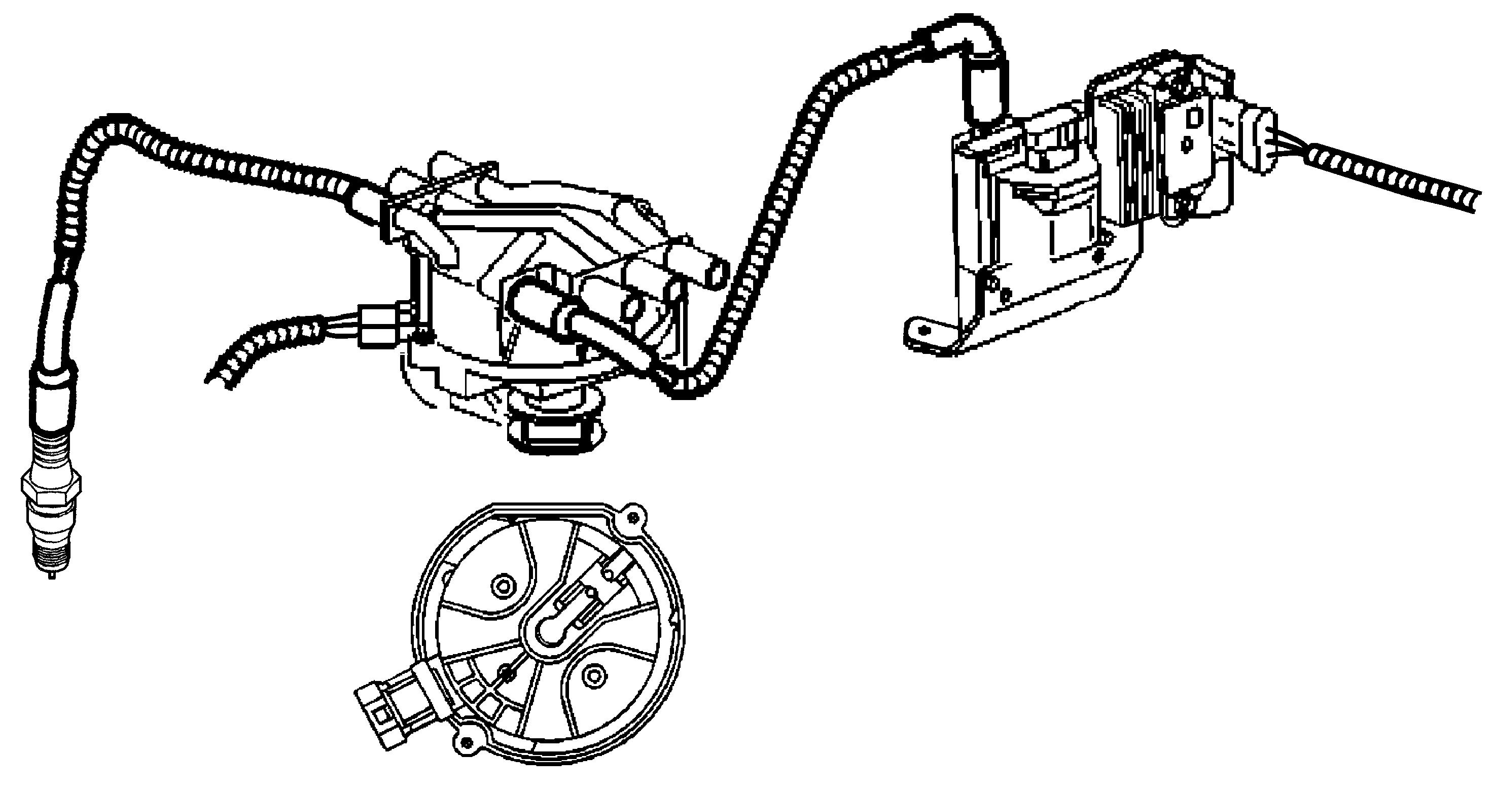
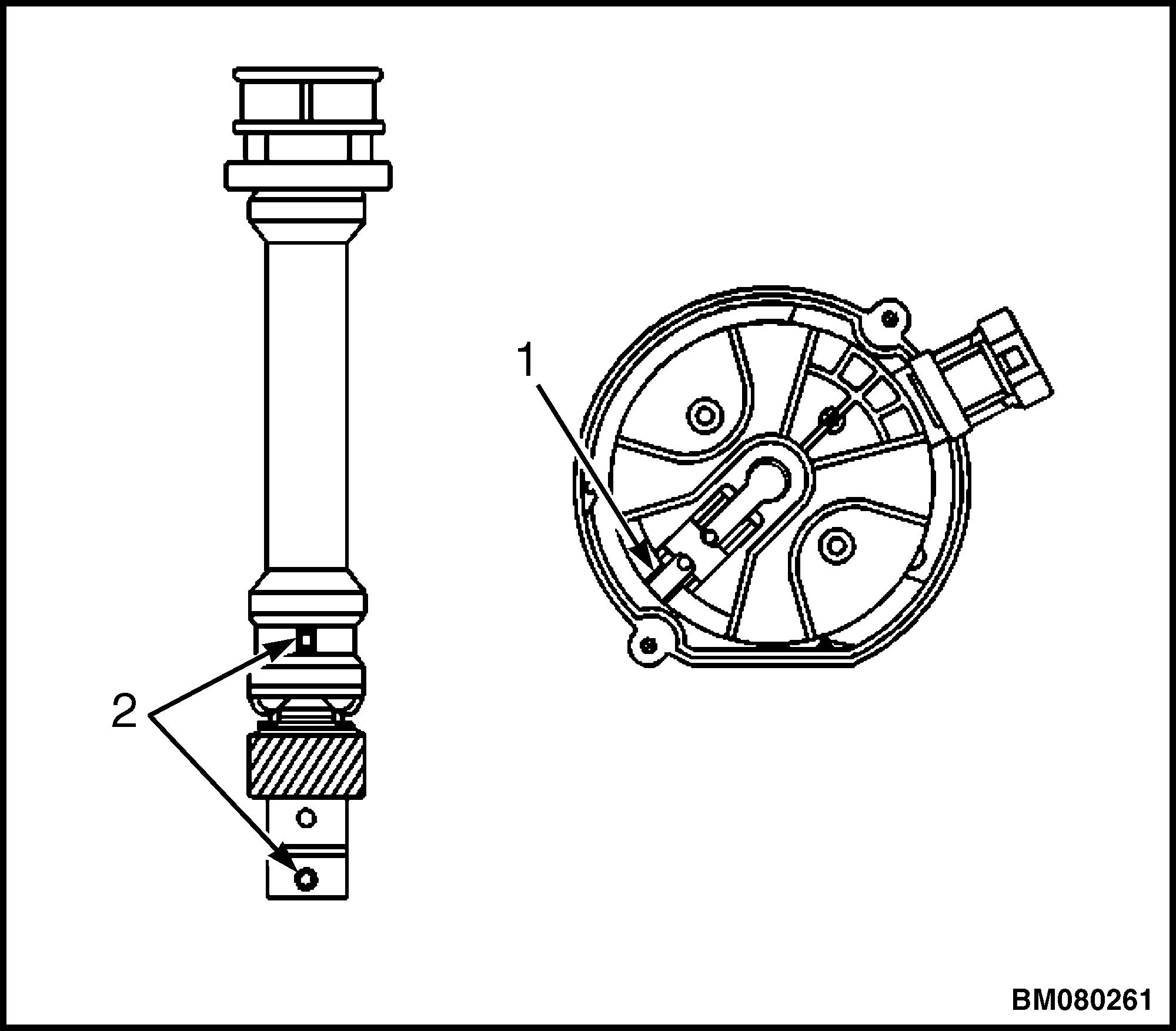
1. Disconnect the spark plug wire at each spark plug. See Figure 1.
a. Twist the boots 1/2 turn before removing the boots.
b. Pull only on the boot or use a tool designed for this purpose in order to remove the wire from each spark plug.
1.SPARK PLUG WIRES
Figure 1. Spark Plug Wire Removal/Installation
2. Disconnect the spark plug wire from the distributor.
a. Twist each spark plug boot 1/2 turn.
b. Pull only on the boot or use a tool designed for this purpose in order to remove the wires from the distributor.
2200 YRM 1097 Spark Plugs and Wires 3
Install
NOTE: If the boot-to-wire movement has occurred, the boot will give a false visual impression of being fully seated. Ensure that the boots have been properly assembled by pushing sideways on the installed boots. Failure to properly seat the terminal onto the spark plug will lead to wire core erosion and result in an engine misfire or crossfire condition and possible internal damage to the engine.
1. Install the spark plug wires at the distributor.
2. Install the spark plug wire to each spark plug. See Figure 1.
3. Inspect the wires for proper installation:
a. Push sideways on each boot in order to inspect the seating.
b. Reinstall any loose boot.
c. Wire routing must be kept intact during service and followed exactly when wires have been disconnected or when replacement of the wires is necessary. Failure to route the wires properly can lead to radio ignition noise and cross firing of the plugs or shorting of the leads to the ground.
d. Any time the spark plug wires or boots are installed on the spark plugs, new dielectric grease needs to be applied inside the boot.
SPARK PLUG INSPECTION
Usage
1. Ensure that the correct spark plug is installed. An incorrect spark plug causes driveability conditions. Refer to Table 1 for the correct spark plug.
2. Ensure that the spark plug has the correct heat range. An incorrect heat range causes the following conditions:
• Spark plug fouling - Colder plug
• Pre-ignition causing spark plug and/or engine damage - Hotter plug
Inspection
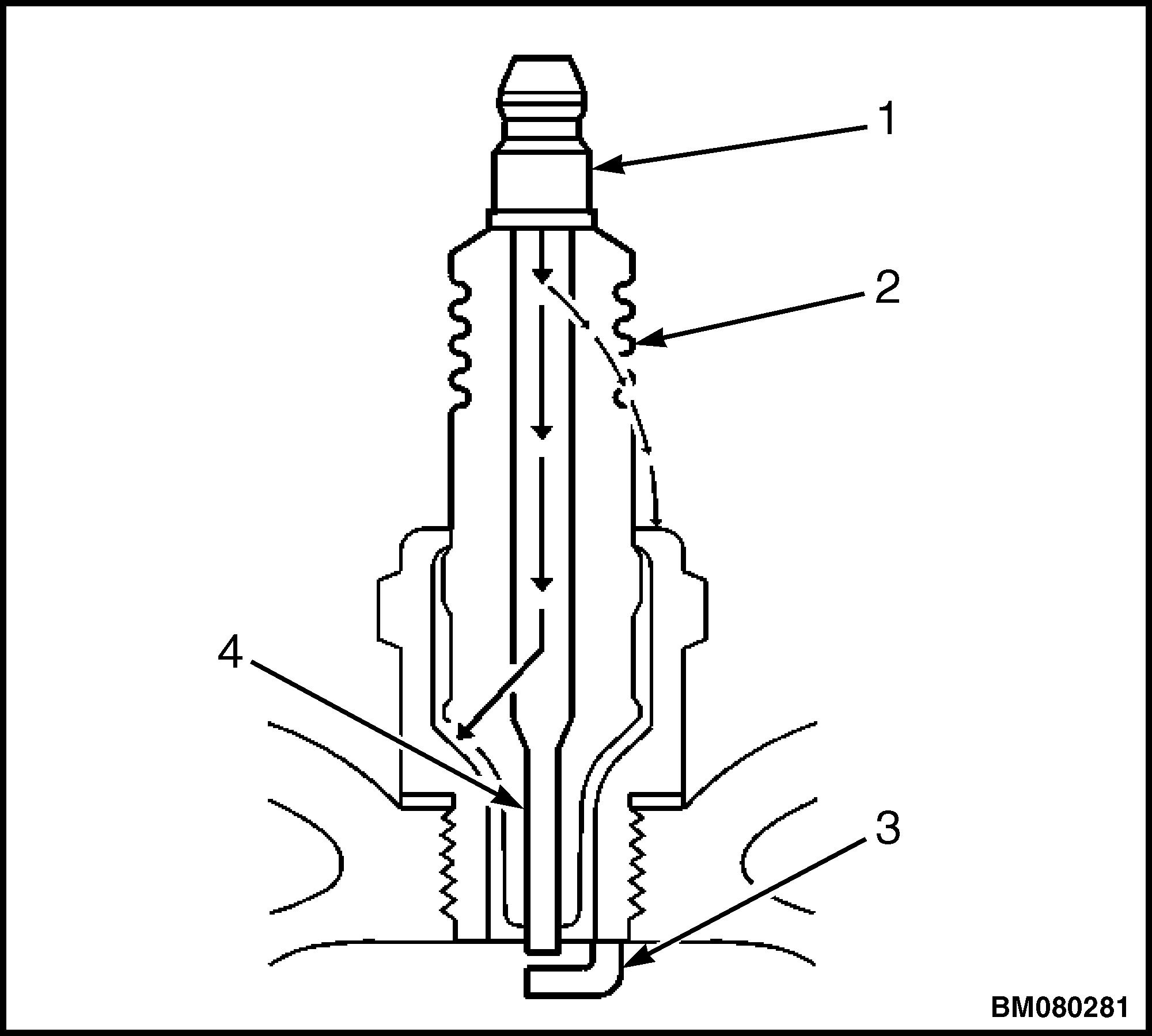
1. Inspect the terminal post for damage. See Figure 2.
a. Inspect for a bent or broken terminal post.
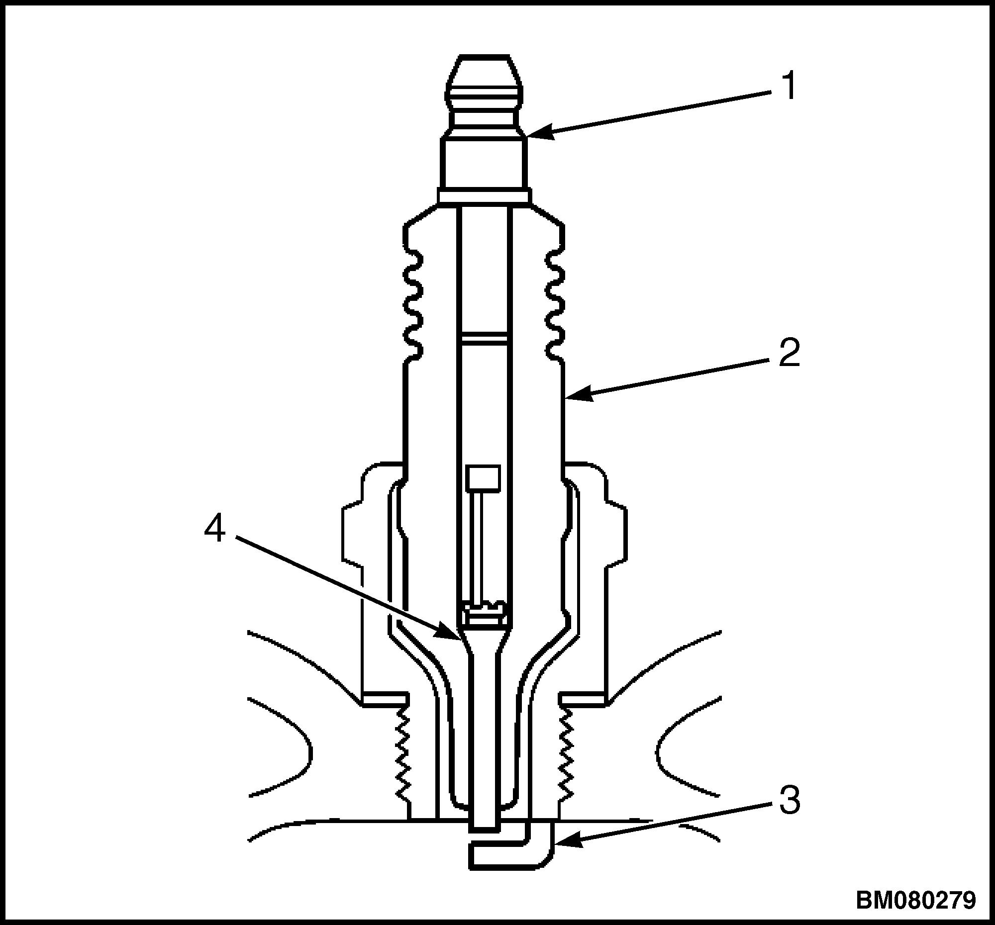
1.TERMINAL POST 2.INSULATOR 3.ELECTRODE 4.ELECTRODE
Figure 2. Spark Plug
b. Test for a loose terminal post by twisting and pulling the post. The terminal post should NOT move.
Spark Plugs and Wires 2200 YRM 1097 4
2. Inspect the insulator for flashover or carbon tracking, soot. See Figure 3. This is caused by the electrical charge traveling across the insulator between the terminal post and ground. Inspect for the following conditions:
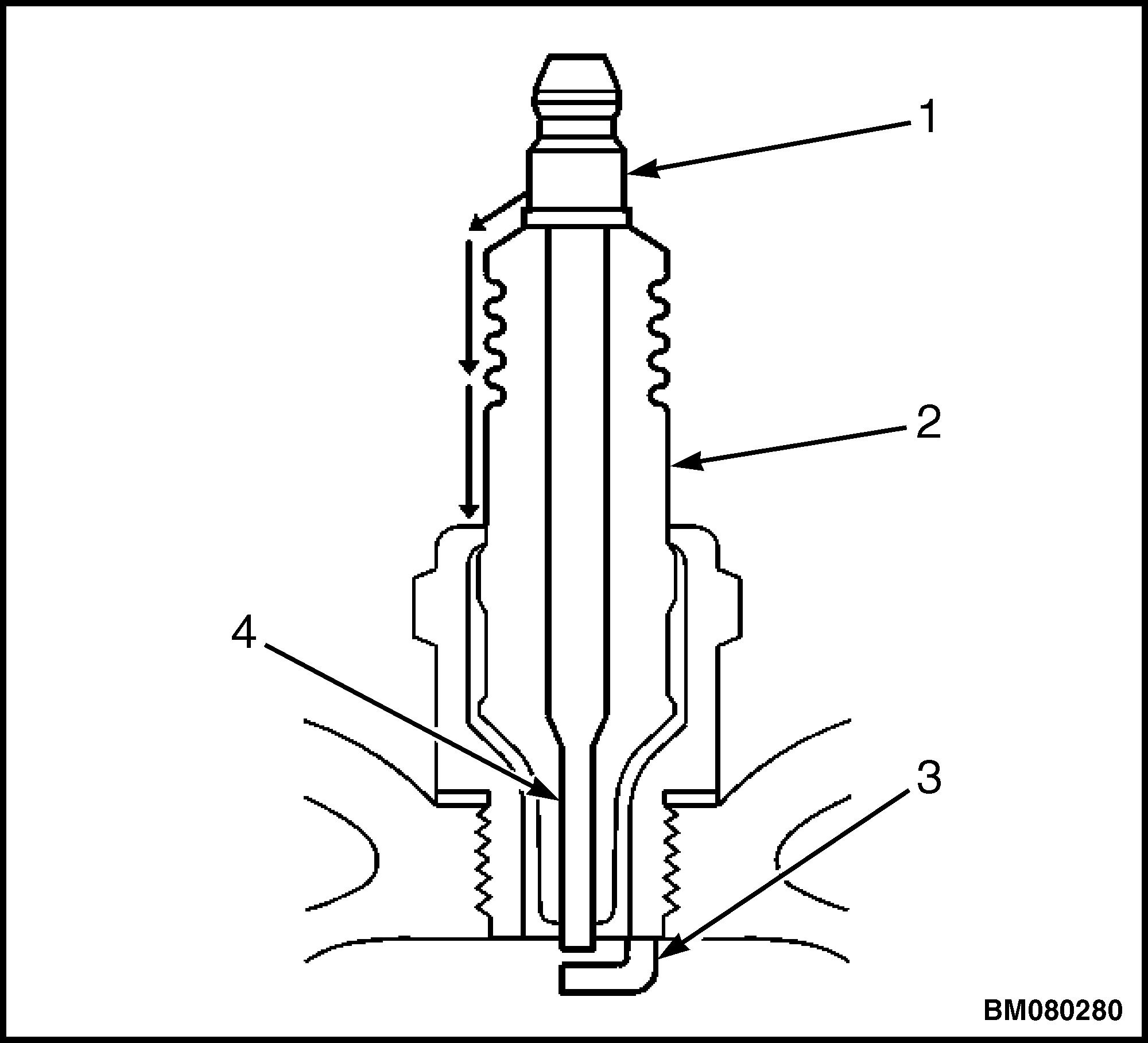
1.TERMINAL POST 2.INSULATOR 3.ELECTRODE 4.ELECTRODE
Figure 3. Spark Plug With Flashover or Carbon Tracking
a. Inspect the spark plug boot for damage.
b. Inspect the spark plug recess area of the cylinder head for moisture, such as oil, coolant, or water. A spark plug boot that is saturated causes arcing to ground.
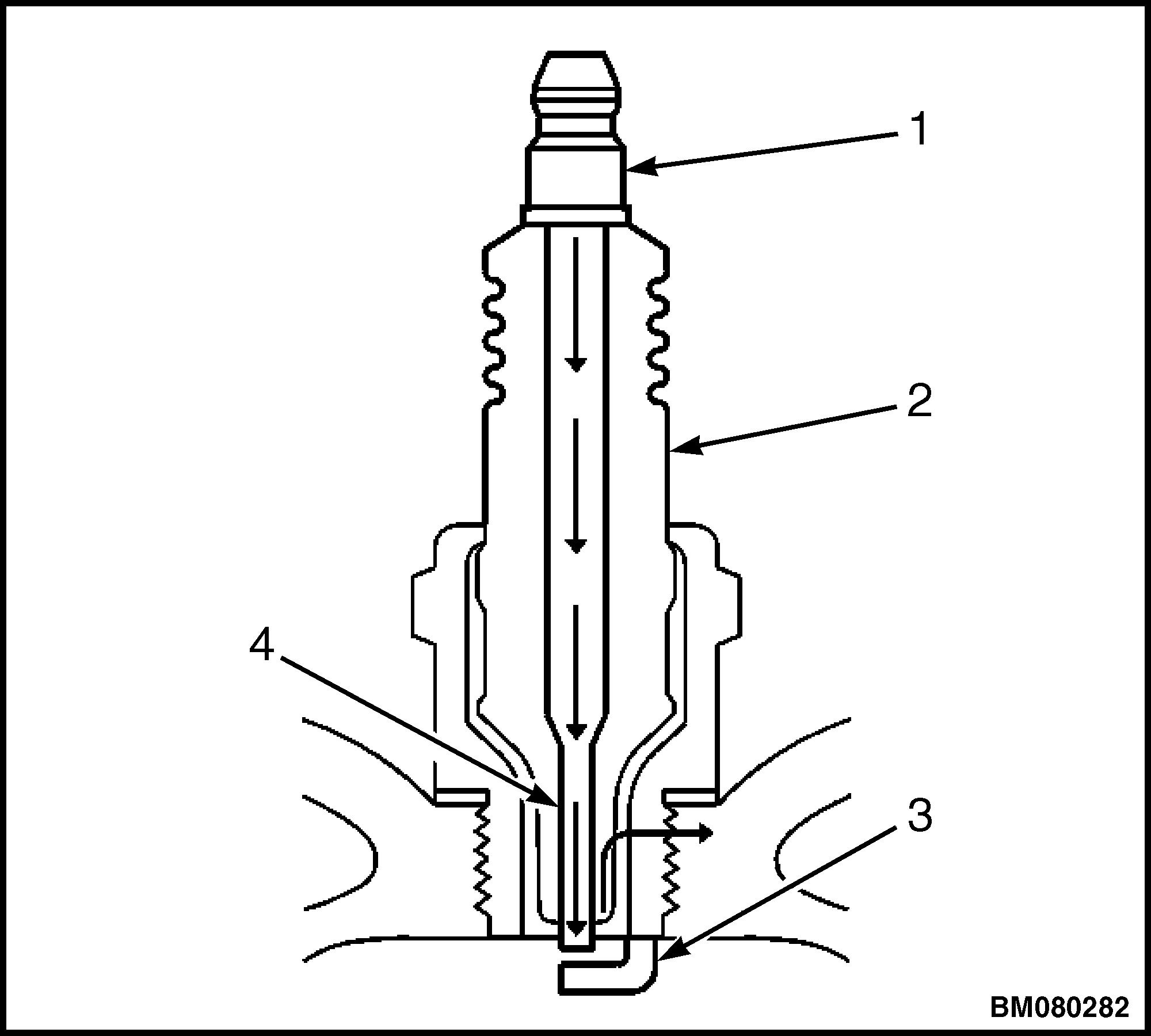
3. Inspect the insulator for cracks. All or part of the electrical charge may arc through the crack instead of the electrodes. See Figure 4.
4. Inspect for evidence of improper arcing. See Figure 5.
a. Measure the gap between the center electrode (4) and the side electrode (3) terminals. An excessively wide electrode gap can prevent correct spark plug operation.
b. Inspect for the correct spark plug torque. Refer to Table 1. Insufficient torque can prevent correct spark plug operation. An over-torqued spark plug causes the insulator to crack.
1.TERMINAL POST 2.INSULATOR 3.ELECTRODE 4.ELECTRODE
Figure 4. Spark Plug Arcing Through a Crack
1.TERMINAL POST 2.INSULATOR 3.ELECTRODE 4.ELECTRODE
Figure 5. Spark Plug Arcing Improperly
c. Inspect for signs of tracking that occurred near the insulator tip instead of the center electrode (4).
d. Inspect for a broken or worn side electrode (3).
2200 YRM 1097 Spark Plugs and Wires 5
e. Inspect for a broken, worn, or loose center electrode (4) by shaking the spark plug.
(1) A rattling sound indicates internal damage.
(2) A loose center electrode (4) reduces the spark intensity.
f. Inspect for bridged electrodes (3, 4). Deposits on the electrodes (3, 4) reduce or eliminate the gap.
g. Inspect for worn or missing platinum pads on the electrodes (3, 4) if equipped.
h. Inspect for excessive fouling.
5. Inspect the spark plug recess area of the cylinder head for debris. Dirty or damaged threads can cause the spark plug not to seat correctly during installation.
Visual Inspection
1. Normal operation - Brown to grayish-tan with small amounts of white powdery deposits are normal combustion by-products from fuels with additives.
2. Carbon fouled - Dry, fluffy black carbon, or soot caused by the following conditions:
• Rich fuel mixtures
• Leaking fuel injectors
• Excessive fuel pressure
• Restricted air filter element
• Incorrect combustion
• Reduced ignition system voltage output
• Weak coils
• Worn ignition wires
• Incorrect spark plug gap
• Excessive idling or slow speeds under light loads can keep spark plug temperatures so low that normal combustion deposits may not burn off.
3. Deposit Fouling - Oil, coolant, or additives that include substances such as silicone, very white coating, reduces the spark intensity. Most powdery deposits will not effect spark intensity unless they form into a glazing over the electrode.
SPARK PLUG REPLACEMENT
Remove
1. Remove the spark plug wires. Refer to Spark Plug Wire Replacement.
2. Loosen each spark plug 1 or 2 turns.
3. Brush or air blast away any dirt from around the spark plugs.
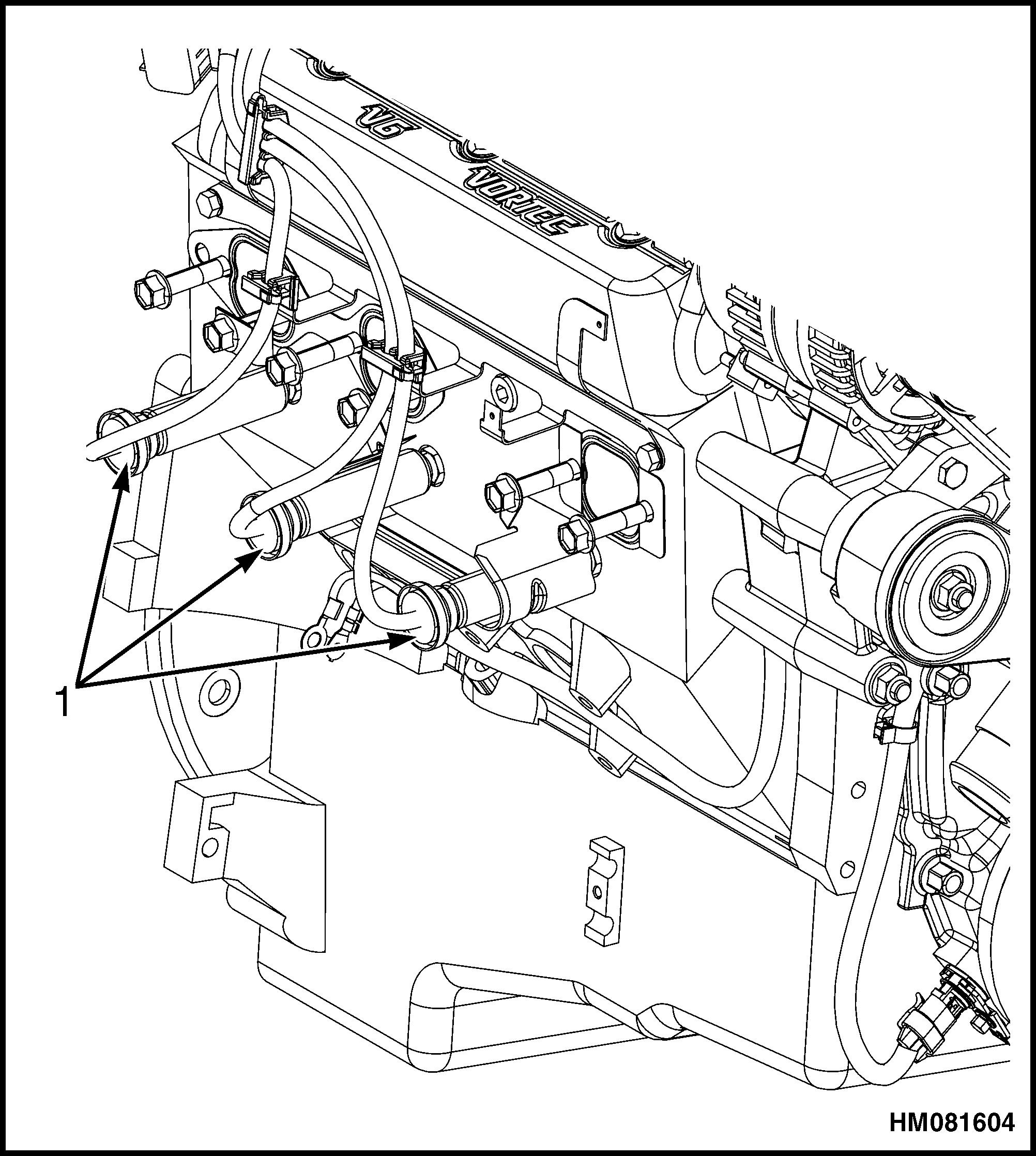
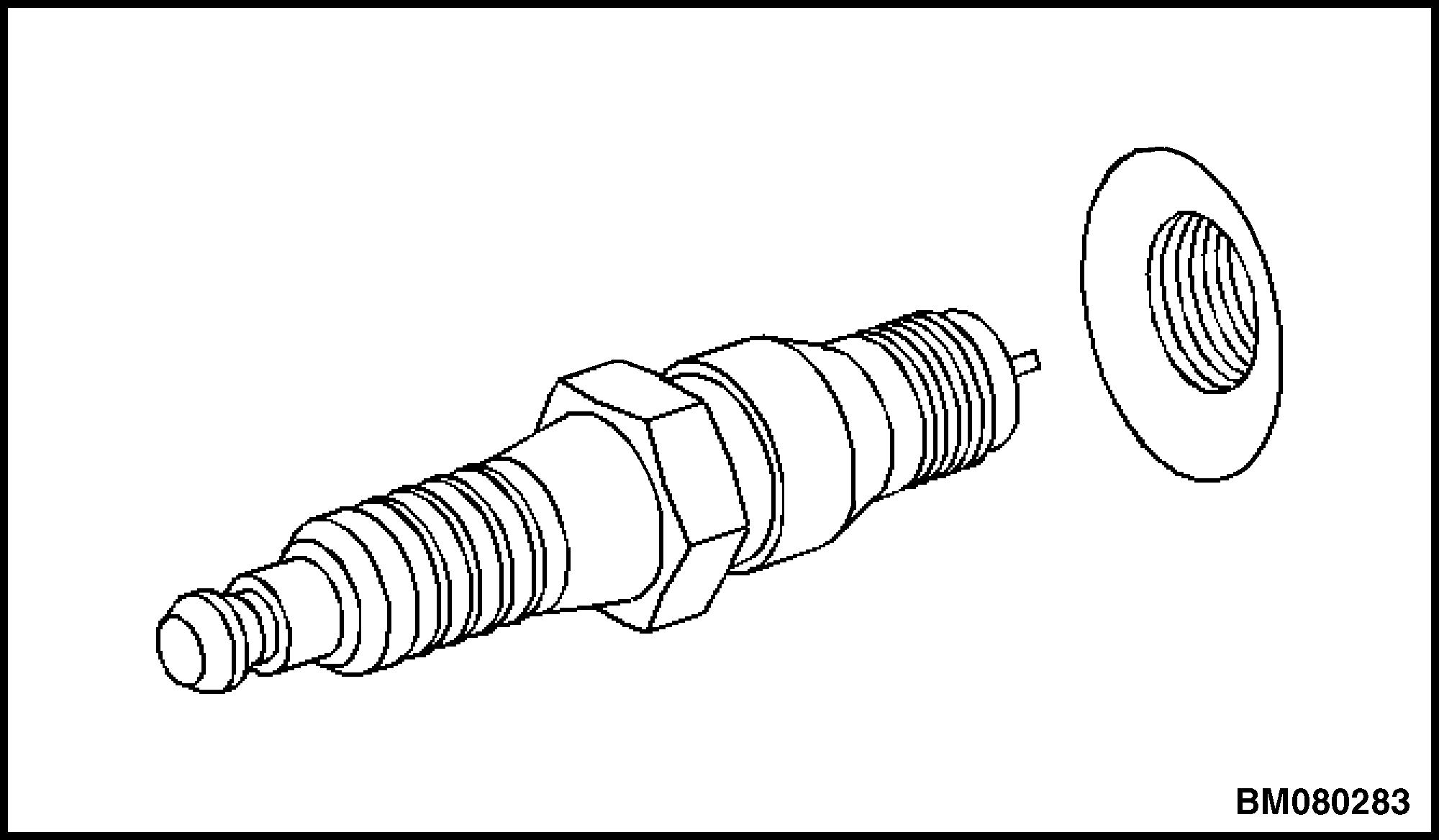
4. Remove the spark plugs one at a time. Place each plug in a tray marked with the corresponding cylinder numbers. See Figure 6.
Install
1. Properly position each spark plug washer.
2. Inspect each spark plug gap. Adjust each plug as needed. See Table 1.
CAUTION
Late model engines use a combination of standard and metric fasteners. The components affected are the starter motor, engine mounts, and flywheel housing mounting. Other components may also have a combination of fasteners. Always verify that the proper fasteners are used whenever removing or replacing any components.
3. Hand start the spark plugs in the corresponding cylinders. See Figure 6.
4. Tighten the spark plugs.
a. For used heads, tighten the spark plugs to 15 N•m (11 lbf ft).
Figure 6. Spark Plug Removal/InstallationSpark Plugs and Wires 2200 YRM 1097 6
b. For new aluminum heads, tighten the spark plugs to 20 N•m (15 lbf ft).
INSPECT
c. For new iron heads, tighten the spark plugs to 30 N•m (22 lbf ft).
Distributor Repair
6. Install the engine cover. Refer to the Frame section for your lift truck.
1. Remove the engine cover. Refer to the Frame section for your lift truck.
NOTE: Discoloration of the cap and some whitish buildup around the cap terminals is normal. Yellowing of the rotor cap, darkening, and some carbon buildup under the rotor segment is normal. Replacement of the cap and the rotor is not necessary unless there is a driveability concern.
2. Inspect the cap for cracks, tiny holes, or carbon tracks between the cap terminal traces. Diagnose the carbon tracks using the following procedure:
a. Remove the cap. Refer to Distributor, Replace.
b. Place 1 lead from the DMM on a cap terminal.
c. Use the other lead in order to probe all other terminals and the center carbon ball.
d. Move the base lead to the next terminal. Probe all other leads.
e. Continue this procedure until you test all the secondary terminals.
f. If there are any non-infinite readings, replace the cap.
3. Inspect the cap for excess buildup of corrosion on the terminals. Scrape clean the terminals. Replace the cap if the corrosion is excessive. Some buildup is normal.
4. Inspect the rotor segment for excess wear. Replace the rotor if excess looseness in the rotor segment is present. See Figure 8.
5. Inspect the shaft for shaft-to-bushing looseness:
a. Inspect the housing for cracks or damage.
b. Insert the shaft in the housing.
c. If the shaft wobbles, replace the housing assembly.
OVERHAUL
Disassemble
1. Remove the engine cover. Refer to the Frame section for your lift truck.
NOTE: The ignition system distributor driven gear and rotor may be installed in multiple positions. In order to avoid mistakes, mark the distributor on the following components in order to ensure the same mounting position upon reassembly:
• Distributor driven gear
• Distributor shaft
• Rotor holes
Installing the driven gear 180 degrees out of alignment, or locating the rotor in the wrong holes, will cause a no-start condition. Premature engine wear or damage may result.
2. Align white paint mark on the bottom stem of the distributor and the pre-drilled indent hole in the bottom of the gear. See Figure 7.
2200 YRM 1097 Distributor Repair 7
Figure 7. Rotor Segment and Distributor Alignment
Legend for Figure 7.
1.ROTOR SEGMENT POSITIONING
2.INDENT HOLE IN BOTTOM OF GEAR
3. With the gear in this position, the rotor segment should be positioned as shown in Figure 7. If not, replace the distributor.
4. Remove the two screws from the rotor. See Figure 8.
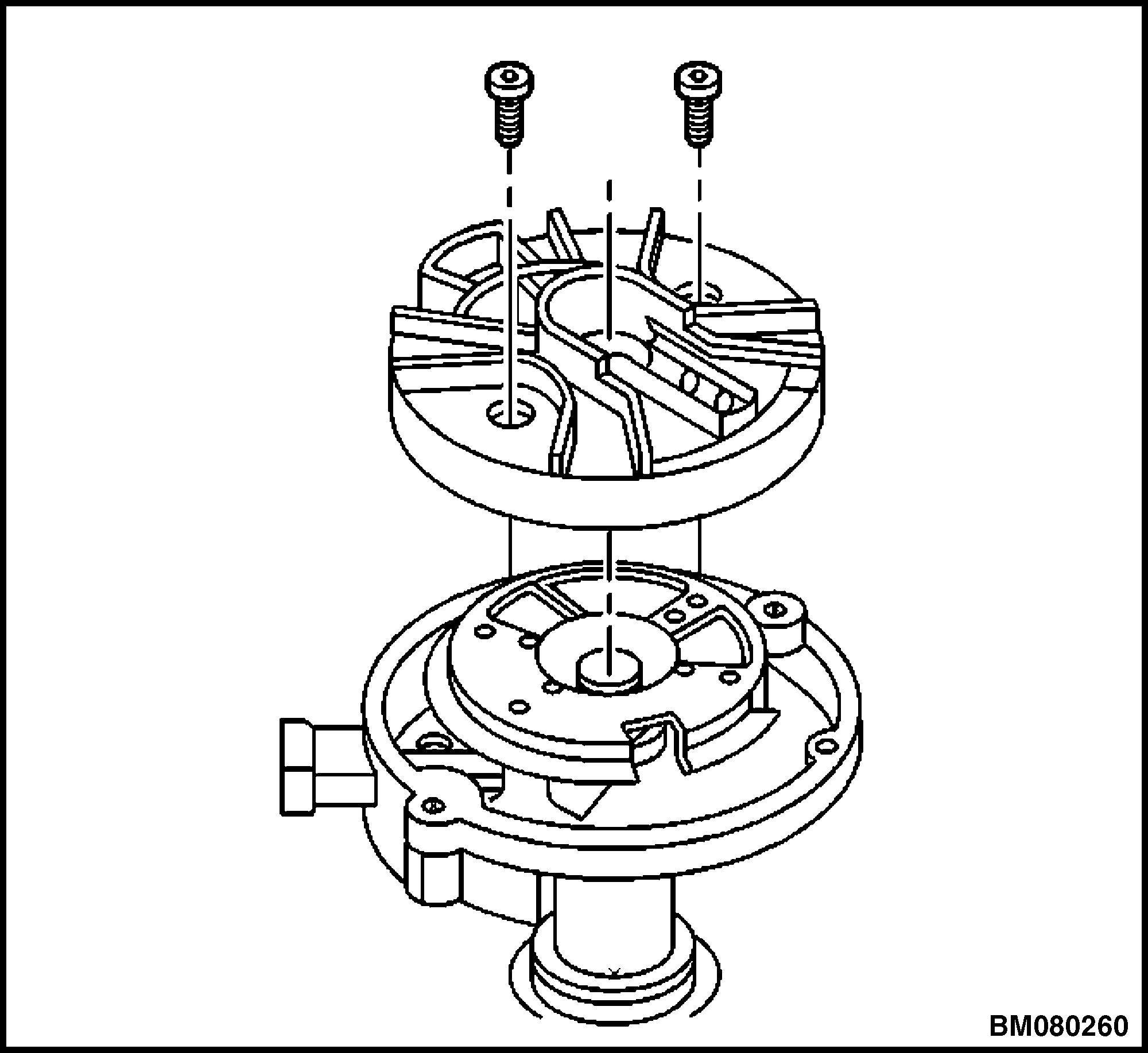
5. Remove the rotor.
6. Note the locating holes that the rotor was removed from (see Figure 9):
• Rotor screw holes (1)
• Rotor locator pin holes (2)
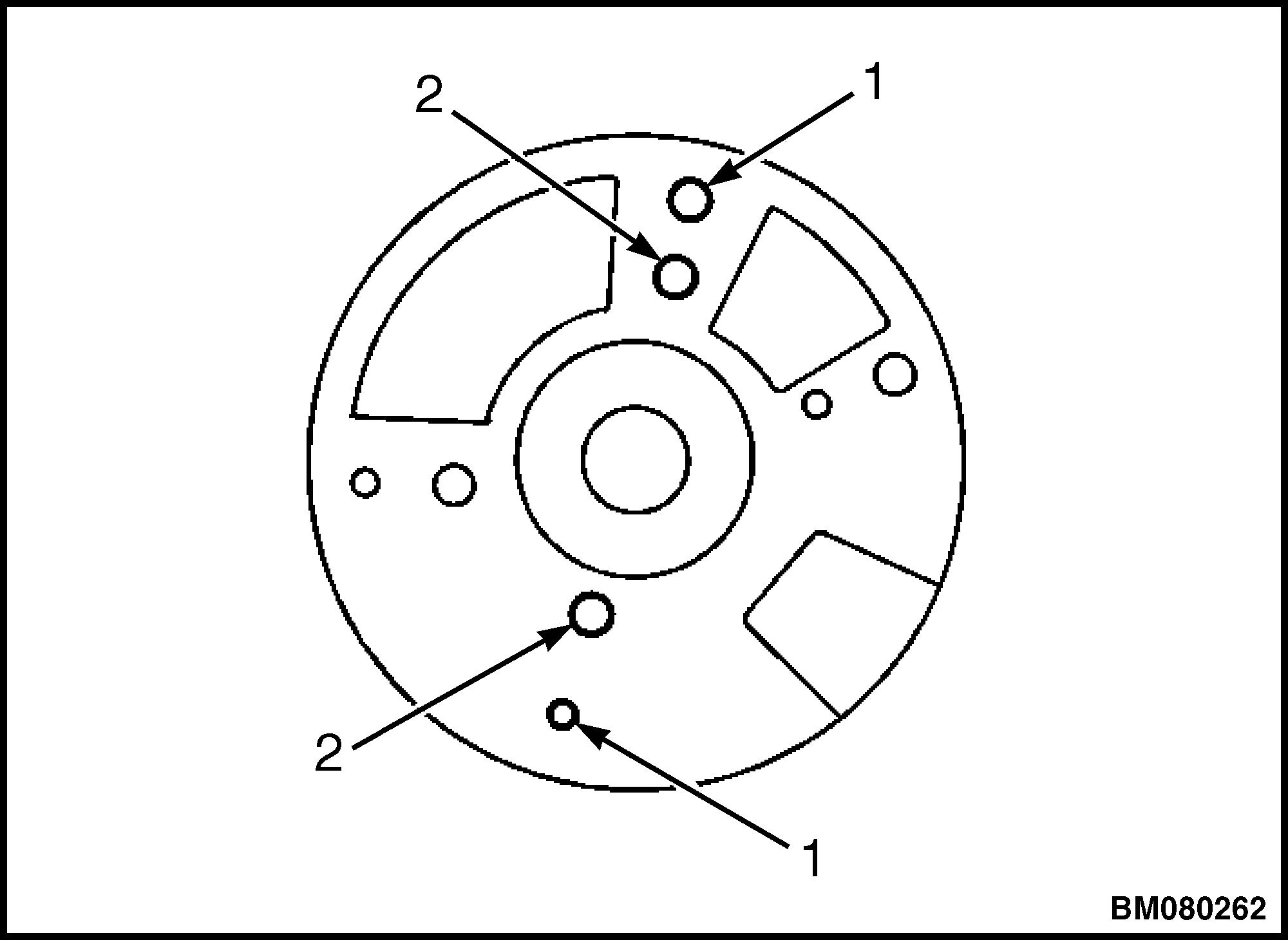
1.ROTOR SCREW HOLE
2.ROTOR LOCATOR PIN HOLE
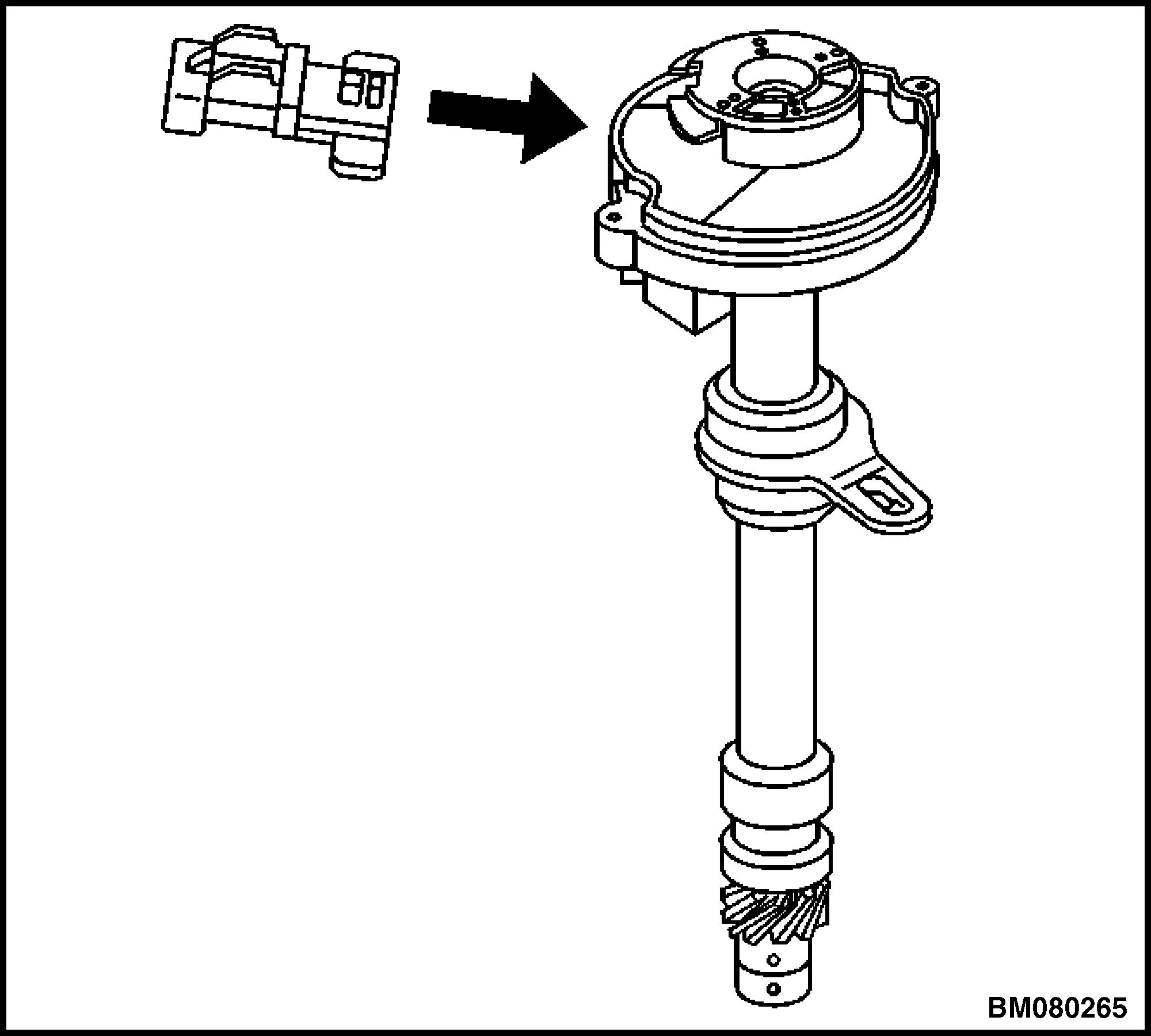
7. Line up the square-cut hole in the vane wheel with the camshaft position (CMP) sensor. See Figure 10.
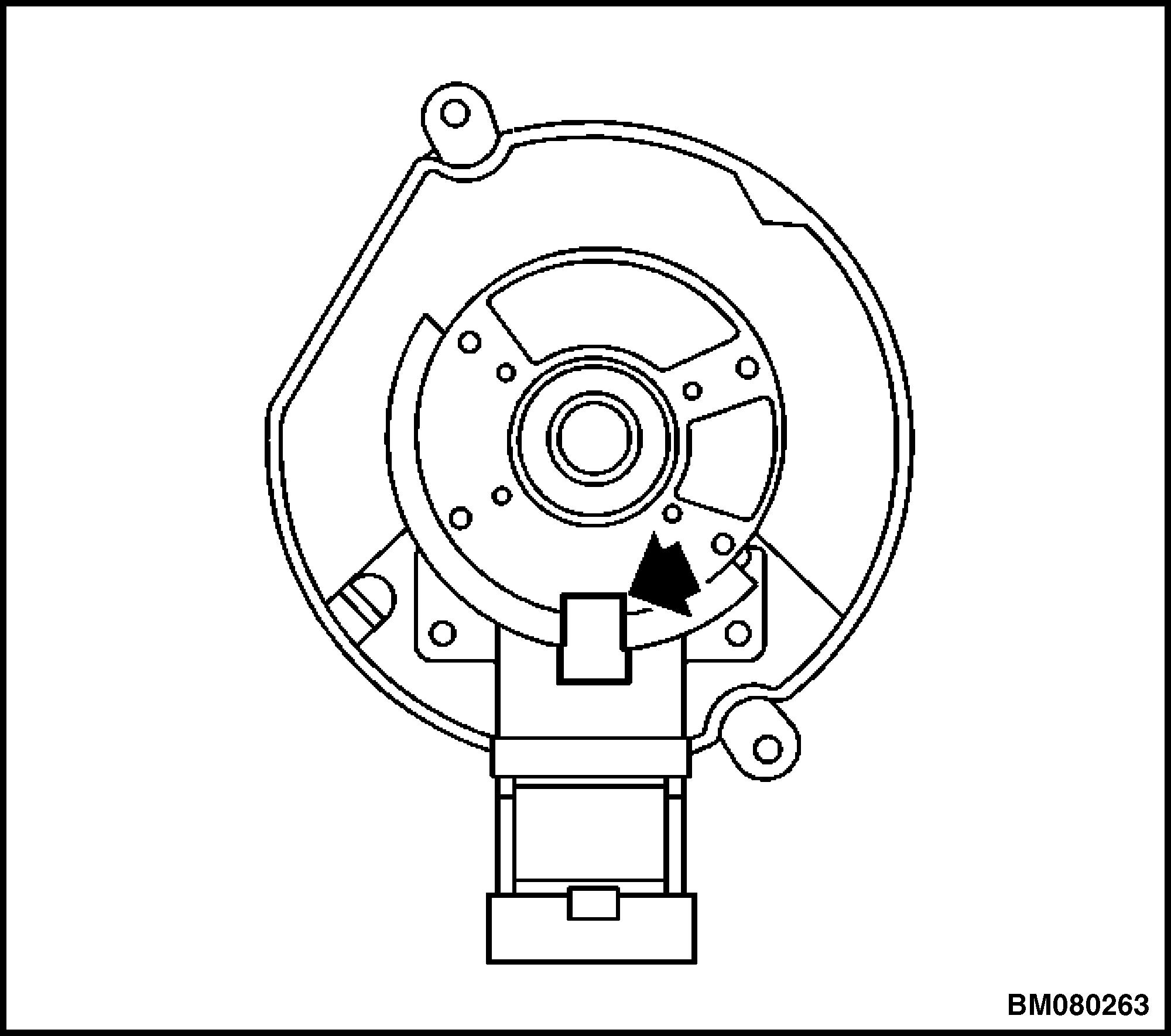 Figure 8. Rotor
Figure 9. Rotor Mounting Holes
Figure 8. Rotor
Figure 9. Rotor Mounting Holes
Distributor Repair 2200 YRM 1097 8
Figure 10. Camshaft Position (CMP) Sensor Alignment
8. Remove the two screws that hold the CMP sensor. See Figure 11.
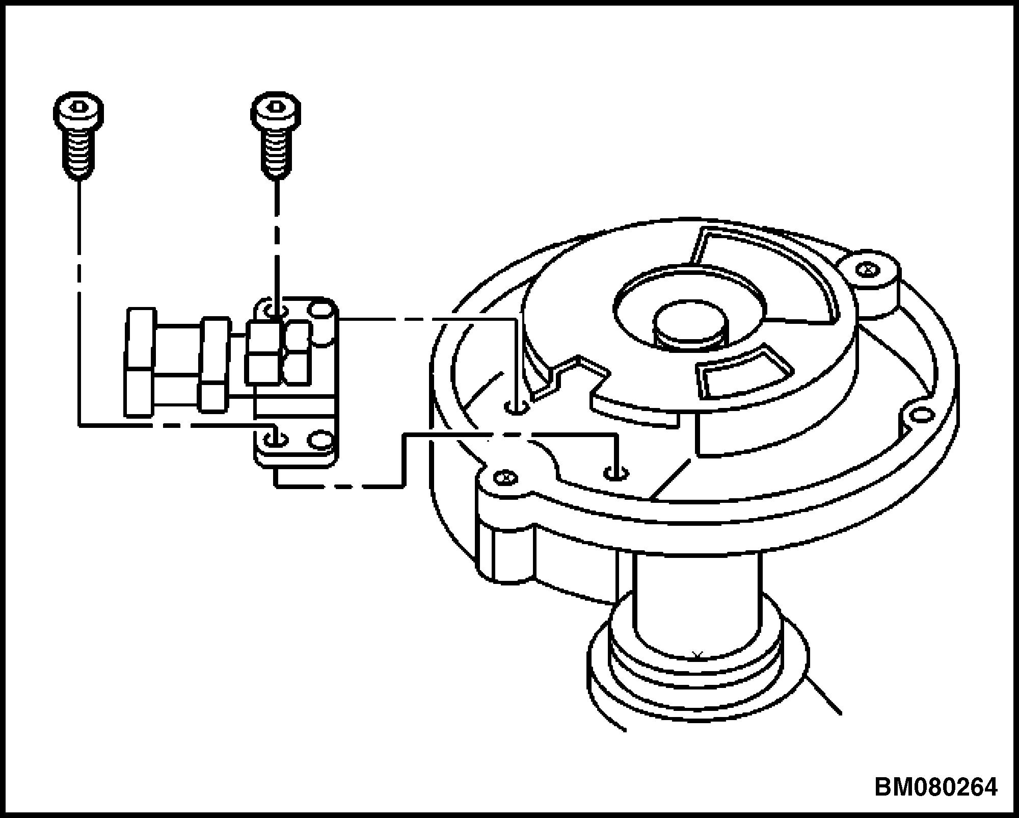
11. Camshaft Position (CMP) Sensor Mounting Screws
9. Discard the screws.
10. Remove the CMP sensor. See Figure 12.
11. Note the dimple located below the roll pin hole on one side of the gear. The dimple will be used to properly orient the gear onto the shaft during reassembly.
12. Support the distributor drive gear in a V-block or similar fixture.
WARNING
To prevent serious eye injury, always wear safe eye protection when performing vehicle maintenance or service.
13. Drive out the roll pin with a suitable punch. See Figure 13.
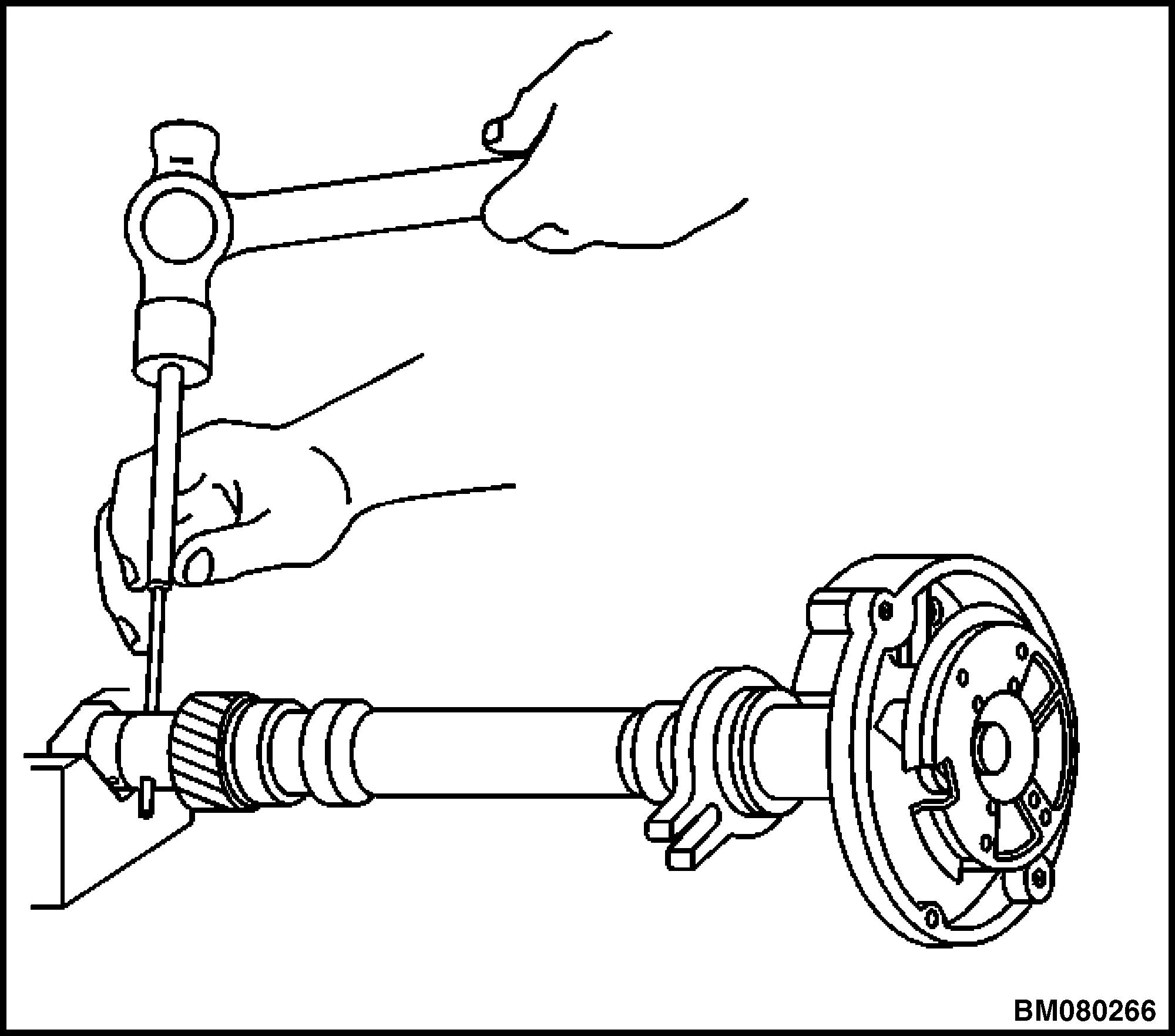
14. Remove the driven gear from the distributor shaft.
15. Remove the round washer.
16. Remove the tang washer.
17. Remove the shim washer. See Figure 14.
Figure Figure 12. Camshaft Position (CMP) Sensor Figure 13. Roll Pin Location2200 YRM 1097 Distributor Repair 9
CLICK HERE TO DOWNLOAD THE COMPLETE MANUAL
• Thank you very much for reading the preview of the manual.
• You can download the complete manual from: www.heydownloads.com by clicking the link below
• Please note: If there is no response to CLICKING the link, please download this PDF first and then click on it.
CLICK HERE TO DOWNLOAD THE
COMPLETE MANUAL
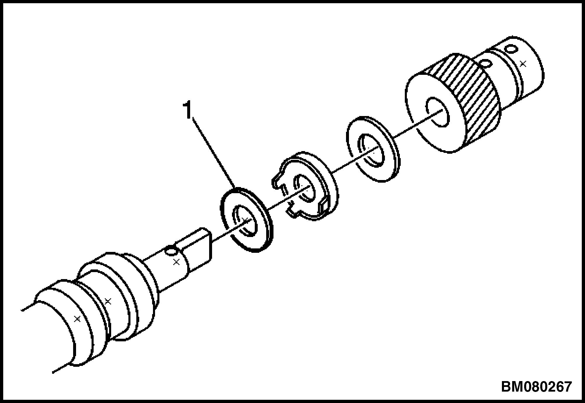
1.SHIM WASHER
Figure 14. Shim Washer Location
18. Remove the old oil seal. See Figure 15.
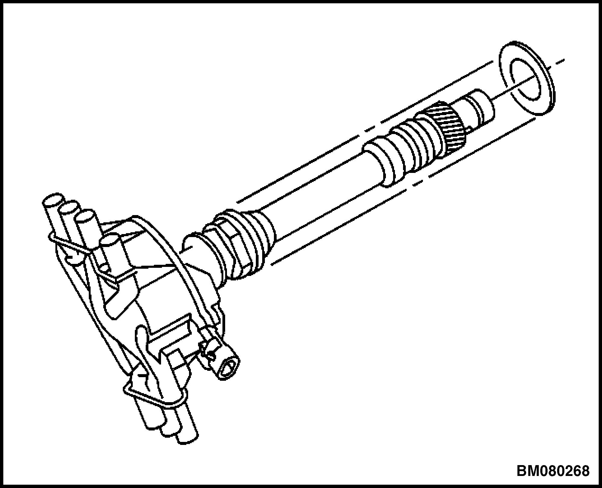
Figure 15. Oil Seal Removal/Installation
Assemble
CAUTION
Installing the driven gear 180 degrees out of alignment or locating the rotor in the wrong holes, will cause a no-start condition. Premature engine wear or damage may result.
1. Line up the square-cut hole in the vane wheel for the CMP sensor. See Figure 10.
2. Insert the sensor into the housing. See Figure 12.
CAUTION
Late model engines use a combination of standard and metric fasteners. The components affected are the starter motor, engine mounts, and flywheel housing mounting. Other components may also have a combination of fasteners. Always verify that the proper fasteners are used whenever removing or replacing any components.
3. Install two new screws for the CMP sensor. Tighten the screws to 2.2 N•m (19 lbf in). See Figure 11.
4. Identify the correct rotor mounting position (see Figure 9):
• At the rotor screw holes (1)
• At the rotor locator pin holes (2)
5. Install the distributor rotor according to the index marks.
6. Install two rotor hold down screws. Tighten the screws to 1.9 N•m (17 lbf in). See Figure 8.
7. Install the shim washer on the bottom of the distributor shaft. See Figure 14.
8. Install the tang washer.
9. Install the round washer.
10. Install the driven gear according to the index marks.
11. Align the rotor segment as shown in Figure 7.
12. Install the gear and align white paint mark on the bottom stem of the distributor and the pre-drilled indent hole in the bottom of the gear.
13. Check to see if the driven gear is installed incorrectly. On an incorrectly installed driven gear, the dimple will be approximately 180 degrees opposite the rotor segment when the gear is installed in the distributor.
14. Support the distributor drive gear in a V-block or similar fixture.
Distributor Repair 2200 YRM 1097 10
WARNING
To prevent serious eye injury, always wear safe eye protection when performing vehicle maintenance or service.
15. Install the roll pin with a suitable punch and hammer in order to hold the driven gear in the correct position. See Figure 13.
16. Install the new oil seal under the mounting flange of the distributor base. See Figure 15.
17. Install the distributor.
18. Install the engine cover. Refer to the Frame section for your lift truck.
REPLACE
Remove
NOTE: There are two procedures available to install the distributor.
Use Install Procedure 1 when the crankshaft has NOT been rotated from the original position.
Use Install Procedure 2 when any of the following components are removed:
• Intake manifold
• Cylinder head
• Camshaft
• Timing chain or sprockets
• Complete engine
If the malfunction indicator lamp (MIL) turns on and DTC P1345 sets after installing the distributor, this indicates an incorrectly installed distributor.
Engine damage or distributor damage may occur. Use Install Procedure 2 in order to install the distributor.
1. Turn OFF the ignition.
2. Remove the engine cover. Refer to the Frame section for your lift truck.
3. Remove air cleaner assembly.
4. Remove the air intake resonator assembly.
5. Remove the ignition coil wire. Note the correct orientation of the wire boot. See Figure 16.

NOTE: V-6 SHOWN, V-8 SIMILAR.
1.COIL WIRE 2.COIL
3.DISTRIBUTOR
Figure 16. Ignition Coil Wire
6. Remove the spark plug wires from the distributor cap.
a. Twist each spark plug 1/2 turn.
b. Pull only on the wire boot in order to remove the wire from the distributor cap.
7. Remove the electrical connector from the base of the distributor.
8. Remove the two screws that retain the distributor cap to the housing. See Figure 17.
2200 YRM 1097 Distributor Repair 11
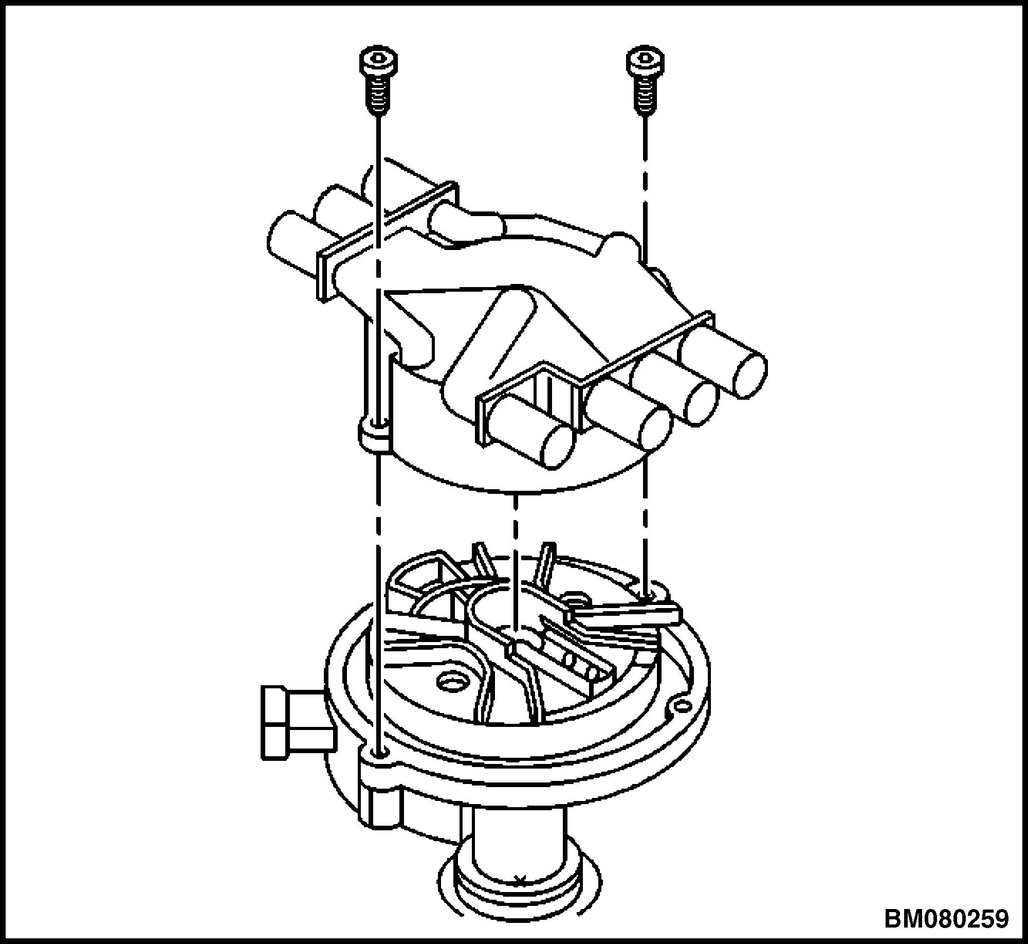
Figure 17. Distributor Cap Removal/Installation
Legend for Figure 17.
NOTE: V-6 SHOWN, V-8 SIMILAR.
9. Discard the screws.
10. Remove the distributor cap from the housing.
11. Use a grease pencil in order to mark the position of the rotor in relation to the distributor housing shown in Figure 18.
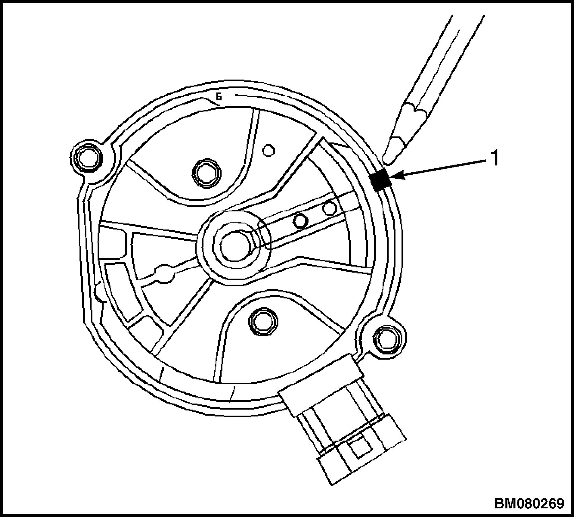
18. Rotor Position Mark
Legend for Figure 18.
1.MARK SHOWING POSITION OF ROTOR IN RELATION TO DISTRIBUTOR HOUSING
12. Mark the distributor housing and the intake manifold with the grease pencil.
13. As the distributor is being removed from the engine, watch the rotor move in a counterclockwise direction about 42 degrees. This will appear as slightly more than one o'clock position. See Figure 19.
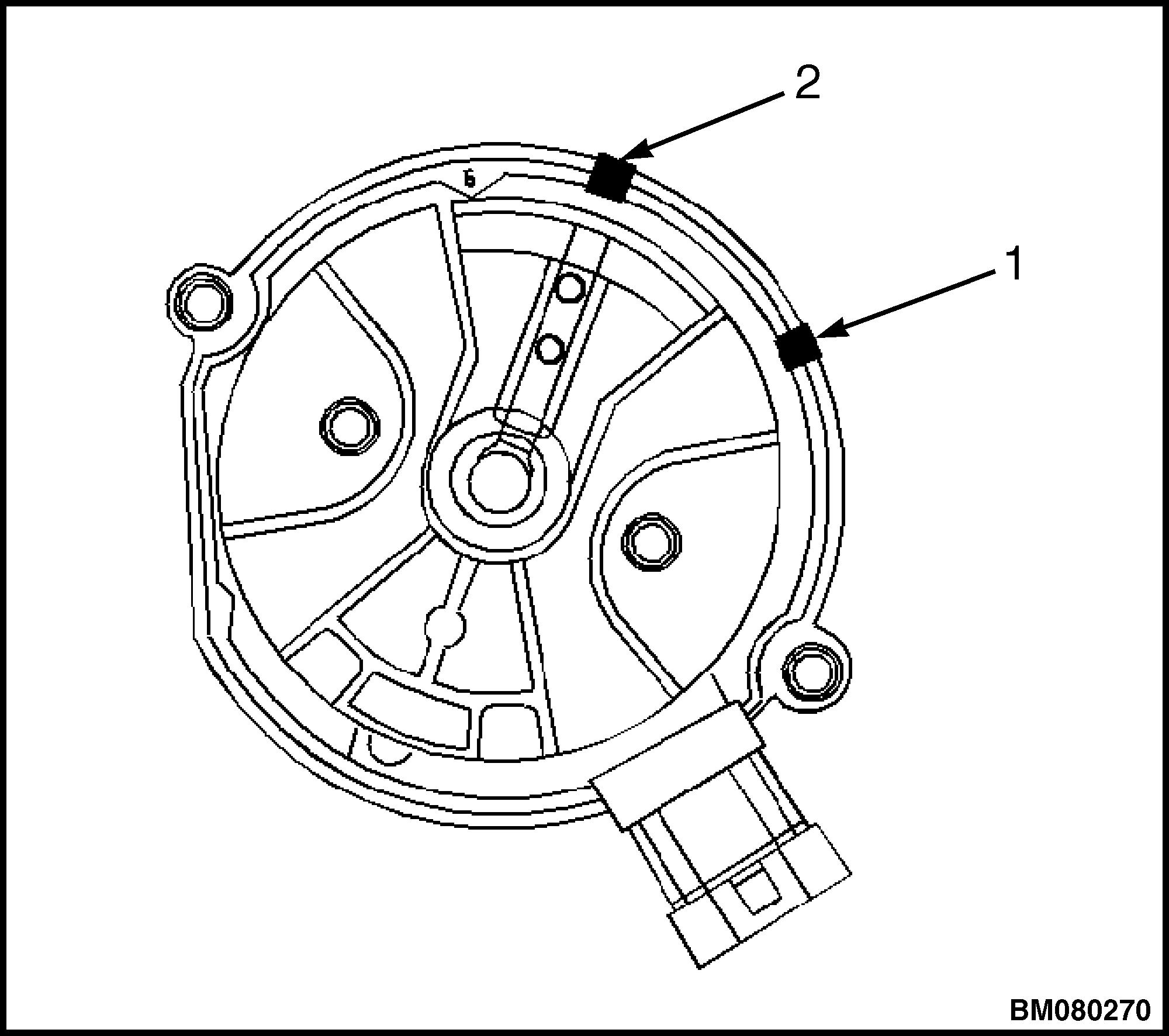
1.MARK SHOWING POSITION OF ROTOR IN RELATION TO DISTRIBUTOR HOUSING
2.MARK ON BASE OF DISTRIBUTOR
Figure 19. Rotor Position in Distributor Housing
14. Note the position of the rotor segment.
15. Place a second mark on the base of the distributor.
This will aid in achieving the proper rotor alignment during the distributor installation.
16. Remove the mounting clamp holddown bolt. See Figure 20.
FigureDistributor Repair 2200 YRM 1097 12
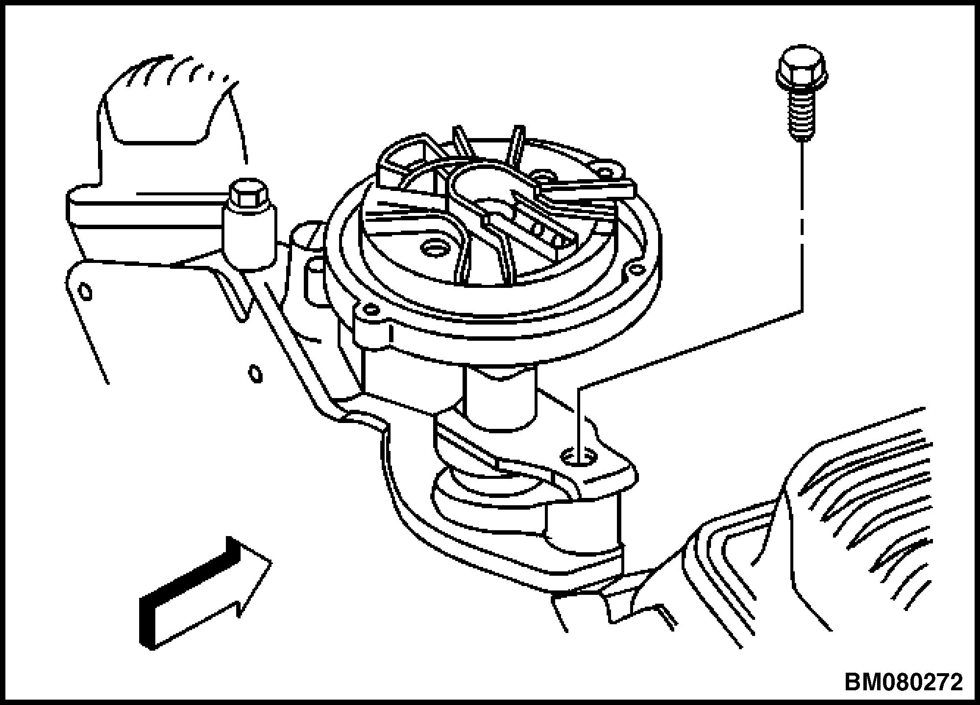
Figure 20. Distributor Mounting Clamp Bolt
17. Remove the distributor. See Figure 21.
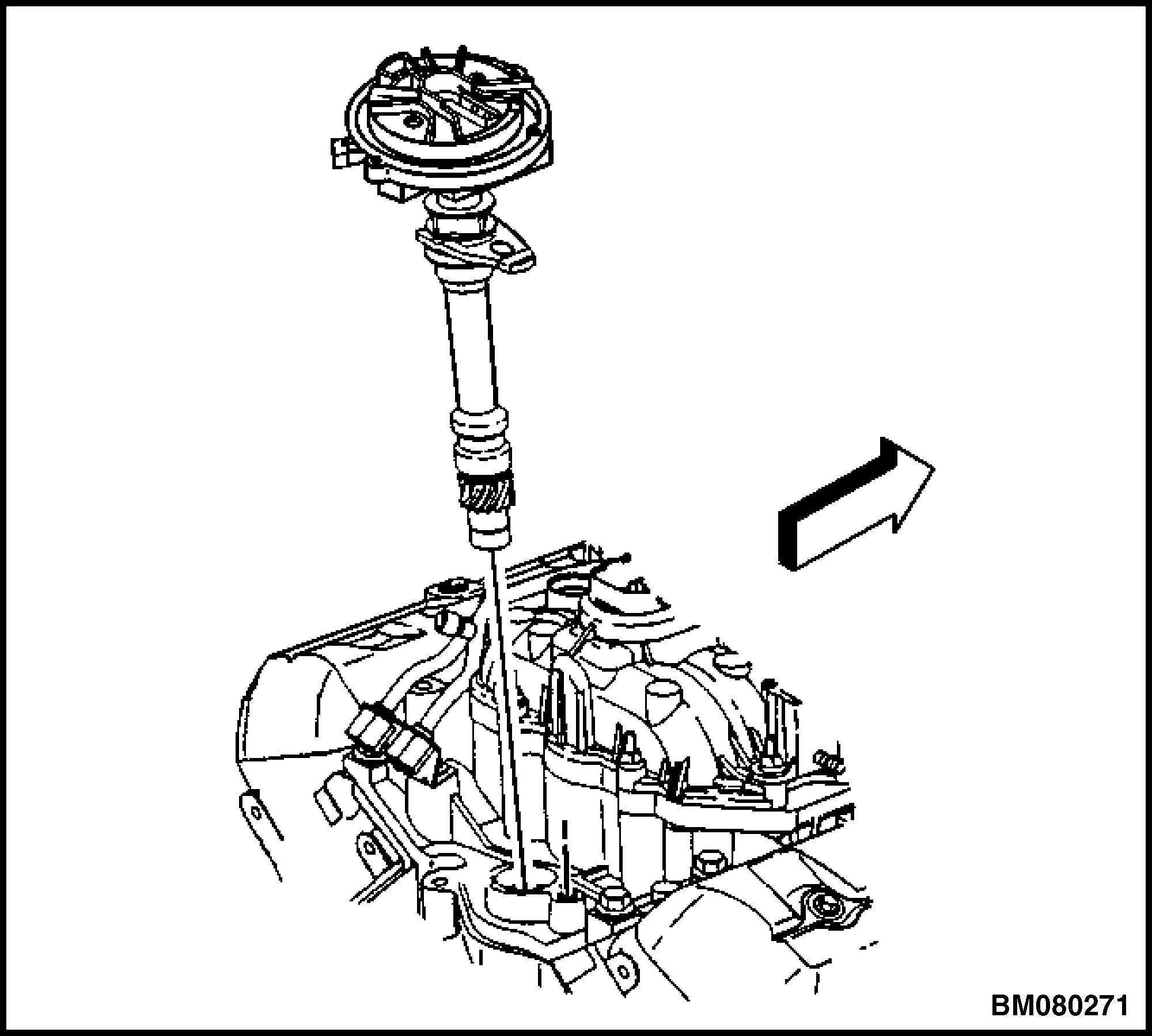
Figure 21. Distributor Removal/Installation
Install Procedure 1
1. If installing a new distributor assembly, place two marks on the new distributor housing in the same location as the marks on the original housing. See Figure 19.
2. Remove the new distributor cap if necessary.
3. Align the rotor with the second mark.
4. Guide the distributor into the engine. See Figure 21.
5. Align the hole in the distributor holddown base over the mounting hole in the intake manifold.
6. As the distributor is being installed, observe the rotor moving in a clockwise direction about 42 degrees. See Figure 18.
7. Once the distributor is completely seated, the rotor segment should be aligned with the mark on the distributor base.
• If the rotor segment is not aligned with the mark, the driven gear teeth and the camshaft have meshed one or more teeth out of alignment.
• In order to correct this condition, remove and reinstall the distributor.
CAUTION
Late model engines use a combination of standard and metric fasteners. The components affected are the starter motor, engine mounts, and flywheel housing mounting. Other components may also have a combination of fasteners. Always verify that the proper fasteners are used whenever removing or replacing any components.
8. Install the distributor mounting clamp bolt. Tighten the bolt to 25 N•m (18 lbf ft). See Figure 20.
9. Install the distributor cap. See Figure 17.
10. Install the new distributor capscrews. Tighten the capscrews to 2.4 N•m (21 lbf in).
11. Install the electrical connector to the distributor.
12. Install the spark plug wires to the distributor cap.
13. Install the ignition coil wire. Note the correct orientation of the wire boot. See Figure 16.
CAUTION
If the malfunction indicator lamp illuminates after installing the distributor and DTC P1345 is set, the distributor has been installed incorrectly.
14. Refer to Install Procedure 2 if the malfunction indicator lamp illuminates after installing the distributor.
15. Install the engine cover. Refer to the Frame section for your lift truck.
2200 YRM 1097 Distributor Repair 13
Install Procedure 2
NOTE: Rotate the number 1 cylinder to top dead center (TDC) of the compression stroke. The engine front cover has two alignment tabs and the crankshaft balancer has two alignment marks spaced 90 degrees apart which are used for positioning the number 1 piston at TDC. See Figure 22. With the piston on the compression stroke and at TDC, the crankshaft balancer alignment mark (1) must align with the engine front cover tab (2) and the crankshaft balancer alignment mark (4) must align with the engine front cover tab (3).
1. Rotate the crankshaft balancer clockwise until the alignment marks on the crankshaft balancer are aligned with the tabs on the engine front cover and the number 1 piston is at TDC of the compression stroke. See Figure 22.
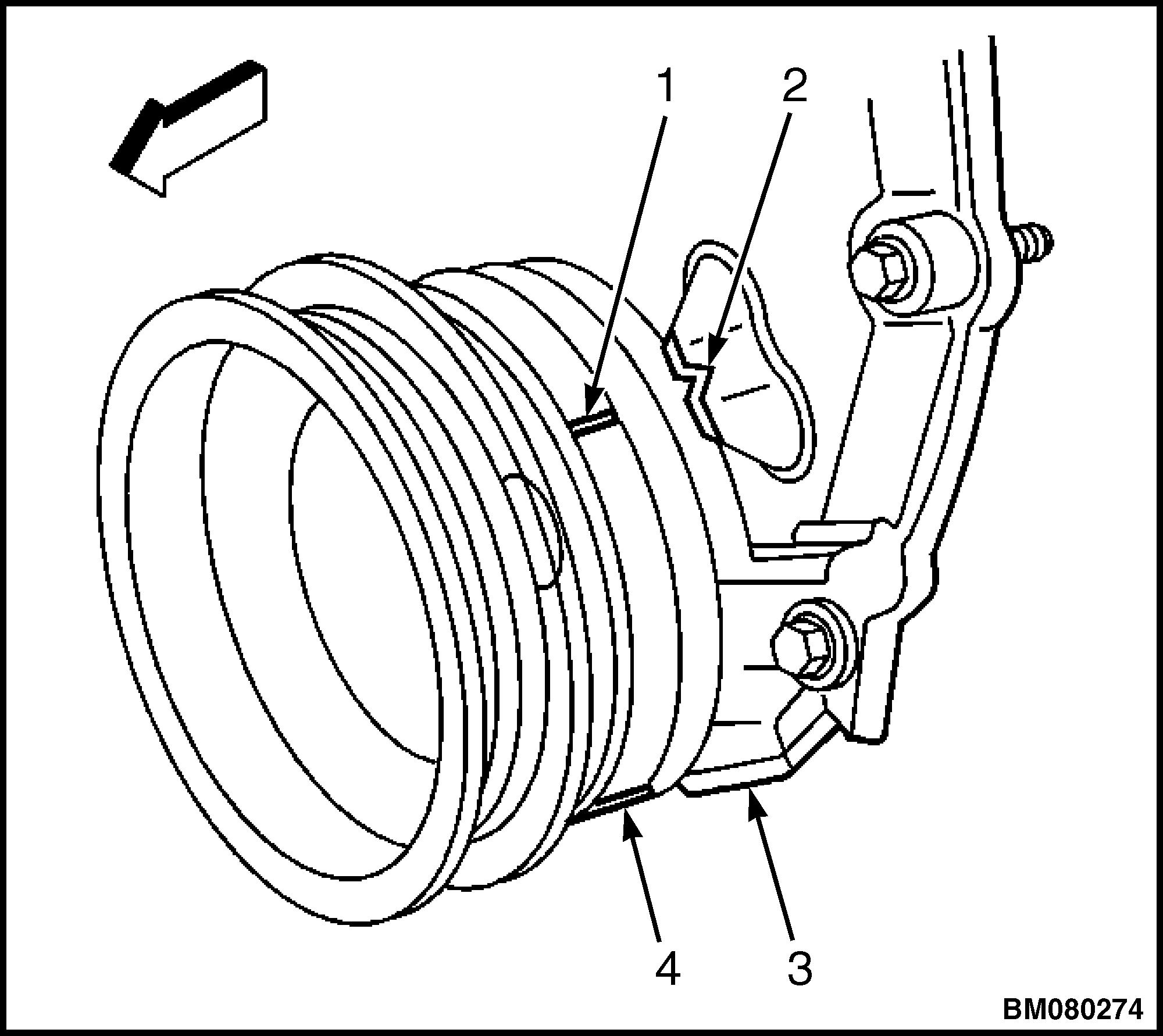
1.CRANKSHAFT BALANCER ALIGNMENT MARK
2.ENGINE FRONT COVER TAB
3.ENGINE FRONT COVER TAB
4.CRANKSHAFT BALANCER ALIGNMENT MARK
NOTE: The ignition system distributor driven gear and rotor may be installed in multiple positions. In order to avoid mistakes, mark the distributor on the following components in order to ensure the same mounting position upon reassembly:
• Distributor driven gear
• Distributor shaft
• Rotor holes
Installing the driven gear 180 degrees out of alignment or locating the rotor in the wrong holes, will cause a no-start condition. Premature engine wear or damage may result.
3. With the gear in this position, the rotor segment should be positioned as shown in Figure 7.
4. Use a long screw driver in order to align the oil pump drive shaft to the drive tab of the distributor.
5. Guide the distributor into the engine. See Figure 21.
Ensure the flat portion of the distributor housing is facing toward the front of the engine.
6. Once the distributor is fully seated, the rotor segment should be aligned with the pointer cast into the distributor base. See Figure 23.
2. Align the white paint mark on the bottom stem of the distributor and the pre-drilled indent hole in the bottom of the gear. See Figure 7.
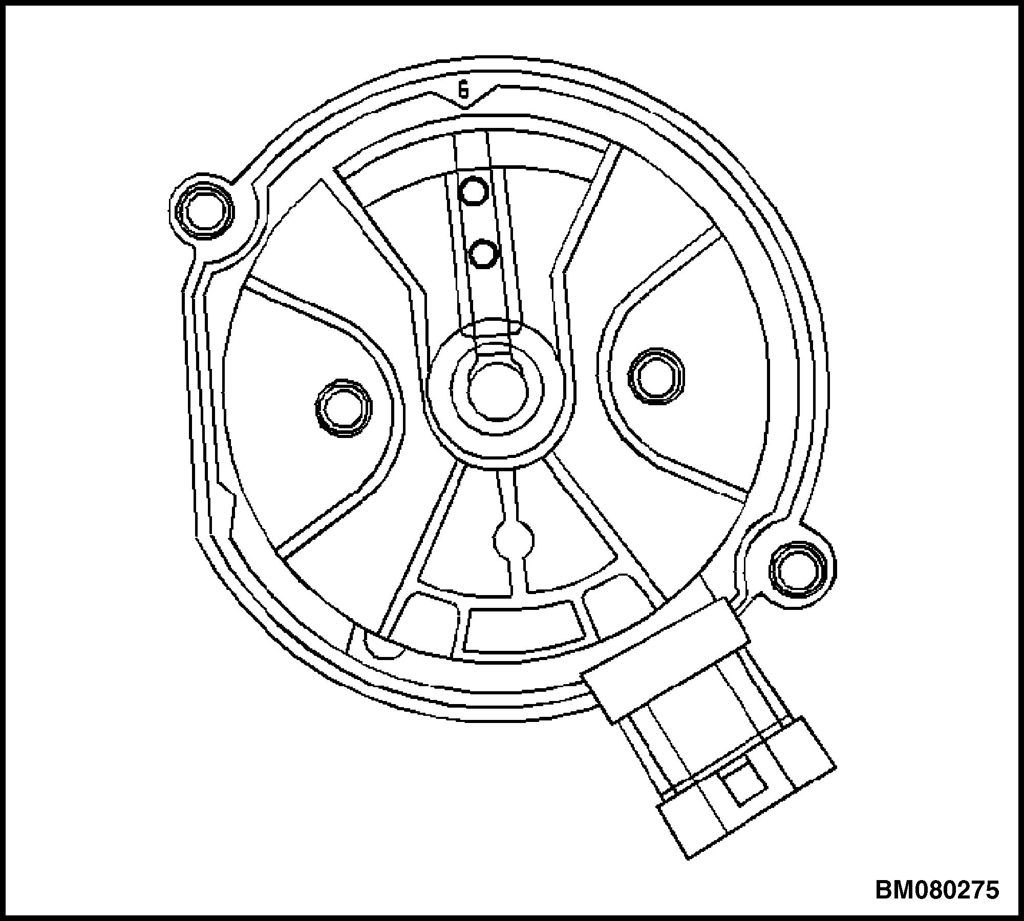 Figure 22. Crankshaft Balancer and Engine Front Cover Alignment Marks
Distributor Repair 2200 YRM 1097 14
Figure 23. Rotor Segment in Distributor Base
If the rotor segment does not come within a few degrees of the pointer, repeat the procedure in order to achieve the proper alignment.
CAUTION
Late model engines use a combination of standard and metric fasteners. The components affected are the starter motor, engine mounts, and flywheel housing mounting. Other components may also have a combination of fasteners. Always verify that the proper fasteners are used whenever removing or replacing any components.
7. Install the distributor mounting clamp bolt. Tighten the bolt to 25 N•m (18 lbf ft). See Figure 20.
8. Install the distributor cap.
9. Install the new distributor capscrews. Tighten the screws to 2.4 N•m (21 lbf in). See Figure 17.
REMOVE
10. Install the electrical connector to the distributor.
11. Install the spark plug wires to the distributor cap.
12. Install the ignition coil wire. Note the correct orientation of the wire boot. See Figure 16.
CAUTION
If the malfunction indicator lamp illuminates after installing the distributor and DTC P1345 is set, the distributor has been installed incorrectly.
13. Repeat Install Procedure 2 if the malfunction indicator lamp illuminates after installing the distributor.
14. Install the engine cover. Refer to the Frame section for your lift truck.
Ignition Coil Replacement
CAUTION
1. Remove the engine cover. Refer to the Frame section for your lift truck.
2. Disconnect the electrical connectors.
3. Remove the ignition coil wire to the distributor. See Figure 24.
4. Remove the studs holding the bracket and the ignition coil to the intake manifold. See Figure 25.
5. Remove the bracket and the ignition coil.
6. Drill and punch out the two rivets holding the ignition coil to the bracket.
7. Remove the ignition coil from the bracket.
INSTALL
NOTE: A replacement ignition coil kit comes with two screws in order to attach the ignition coil to the bracket.
1. Install the ignition coil to the bracket with the two screws.
Late model engines use a combination of standard and metric fasteners. The components affected are the starter motor, engine mounts, and flywheel housing mounting. Other components may also have a combination of fasteners. Always verify that the proper fasteners are used whenever removing or replacing any components.
2. Install the ignition coil and the bracket to the intake manifold with studs. Tighten the studs to 11 N•m (97 lbf in). See Figure 25.
3. Install the ignition coil wire. See Figure 24. The wire must not touch anything like the dipstick. Rubbing will make a ground or short after time of use.
4. Install the electrical connectors.
5. Install the engine cover. Refer to the Frame section for your lift truck.
2200 YRM 1097 Ignition Coil Replacement 15
NOTE: V-6 SHOWN, V-8 SIMILAR.
1.COIL WIRE
2.COIL
3.DISTRIBUTOR
Figure 24. Ignition Coil Wire

NOTE: V -6 SHOWN, V-8 SIMILAR.
1.COIL
2.MOUNTING BOLTS
Figure 25. Ignition Coil
Ignition Control Module Replacement
REMOVE
1. Remove the engine cover. Refer to the Frame section for your lift truck.
2. Disconnect the electrical connector. See Figure 26.
3. Remove the screws holding the ignition control module and the heat sink to the bracket.
4. Remove the ignition control module and the heat sink.
1. Install the ignition control module and the heat sink on the bracket with the screws. Tighten the screws to 3.5 N•m (31 lbf in). See Figure 26.
2. Reconnect the electrical connectors.
3. Install the engine cover. Refer to the Frame section for your lift truck.
INSTALL CAUTION
Late model engines use a combination of standard and metric fasteners. The components affected are the starter motor, engine mounts, and flywheel housing mounting. Other components may also have a combination of fasteners. Always verify that the proper fasteners are used whenever removing or replacing any components.
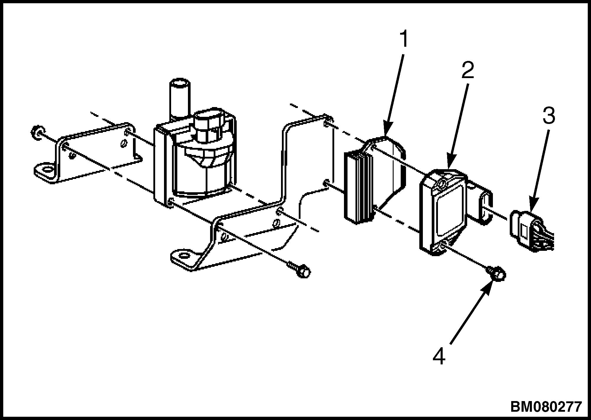
Ignition Control Module Replacement 2200 YRM 1097 16
Figure 26. Ignition Control Module Assembly
1.HEAT SINK
Legend for Figure 26.
2.IGNITION CONTROL MODULE
3.ELECTRICAL CONNECTOR
4.SCREW
Starter Replacement
REMOVE
1. Remove three locknuts, exhaust pipe (5), and two gaskets from exhaust manifold. See Figure 27.
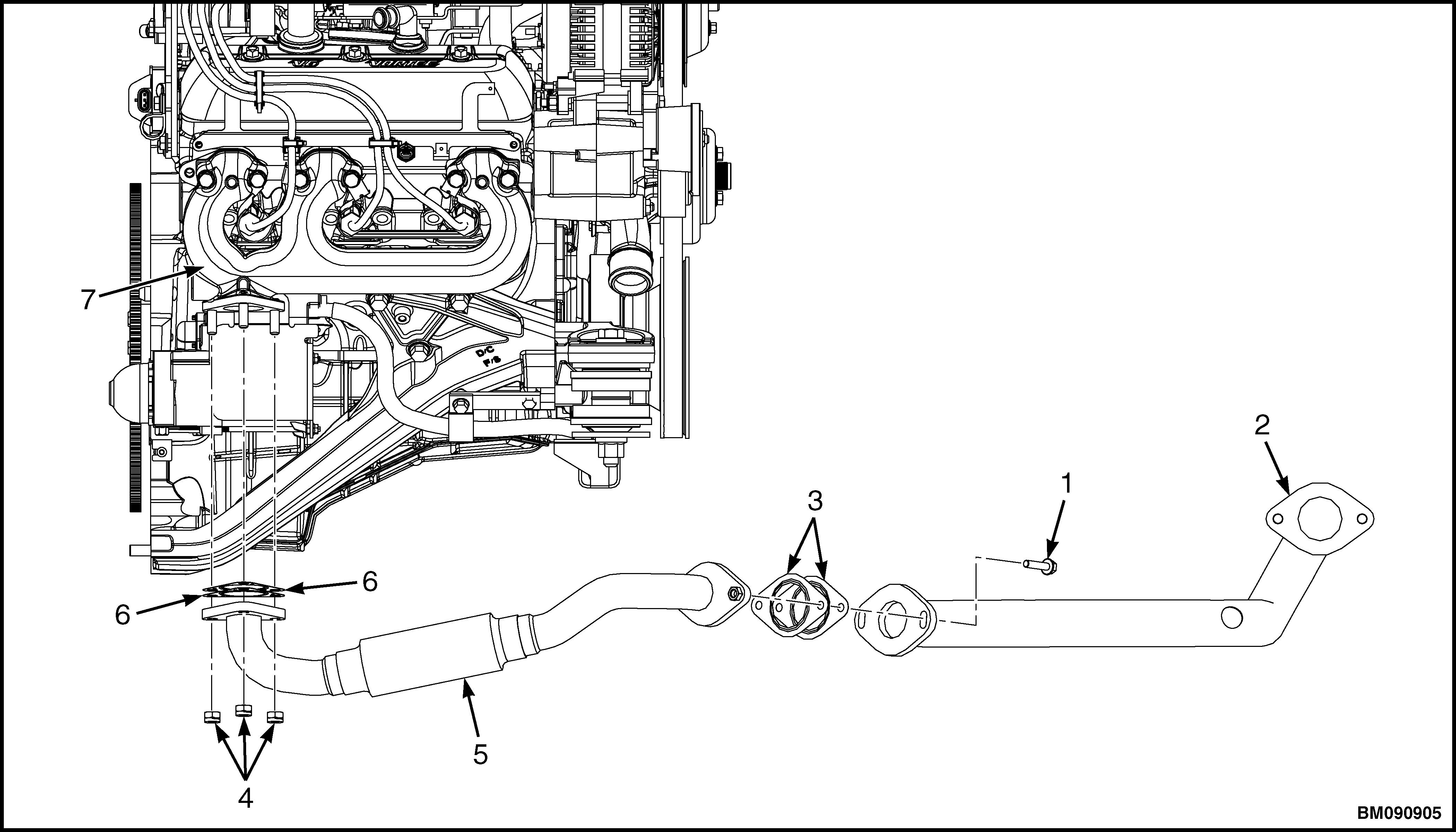
1.CAPSCREW
2.EXHAUST PIPE
3.GASKET
4.LOCKNUT
5.EXHAUST PIPE
6.GASKET
7.EXHAUST MANIFOLD
2200 YRM 1097 Starter Replacement 17
Figure 27. Exhaust Pipe
2. Remove two capscrews, exhaust pipe (5), and two gaskets from exhaust pipe (2). See Figure 27.
3. Disconnect positive (B+) battery cable from starter motor. See Figure 28.
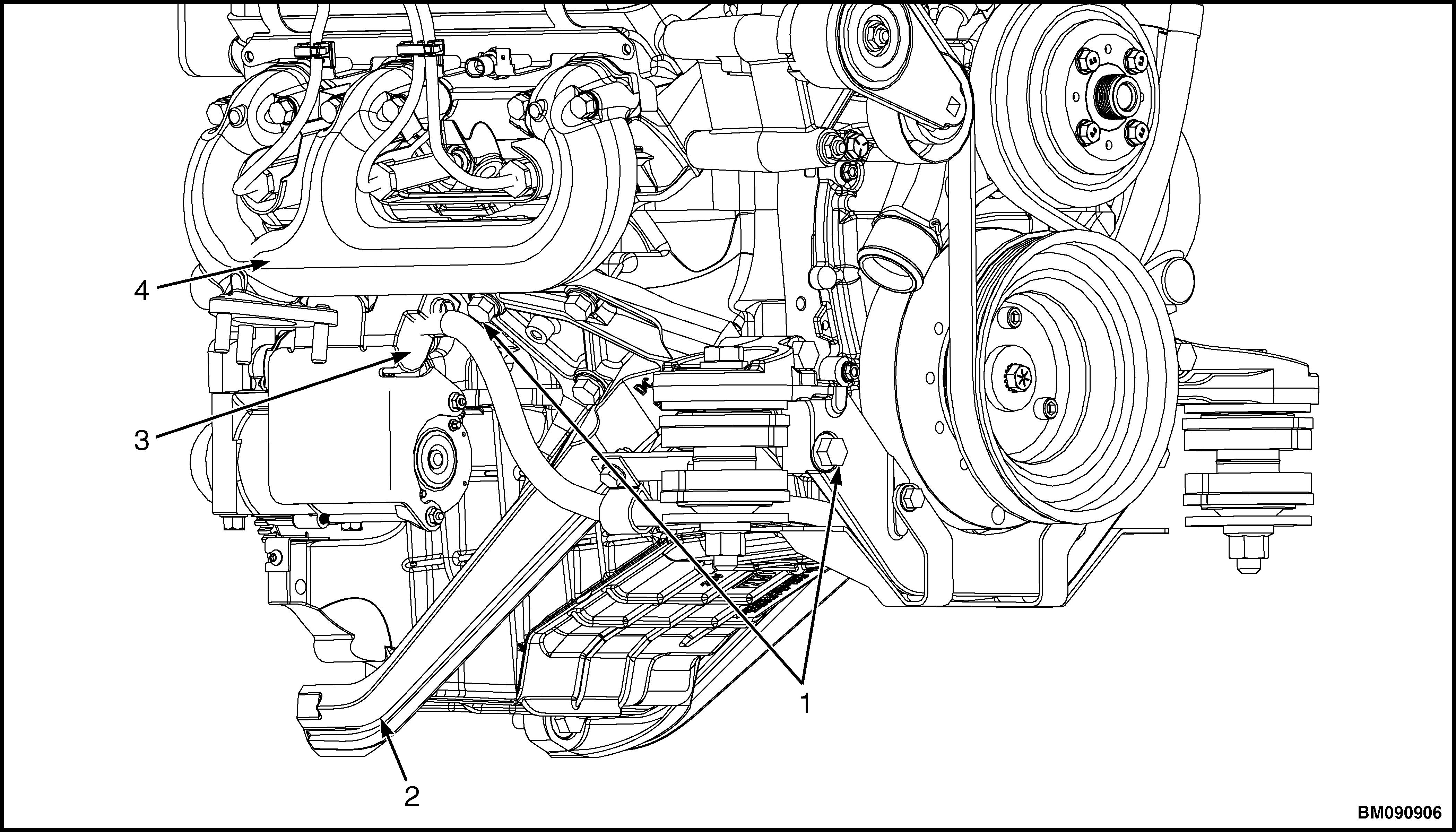
1.CAPSCREW 2.LEFT SIDE ENGINE MOUNT
3.POSITIVE (B+) BATTERY CABLE 4.ENGINE
Starter Replacement 2200 YRM 1097 18
Figure 28. Positive Battery Cable
CLICK HERE TO DOWNLOAD THE COMPLETE MANUAL
• Thank you very much for reading the preview of the manual.
• You can download the complete manual from: www.heydownloads.com by clicking the link below
• Please note: If there is no response to CLICKING the link, please download this PDF first and then click on it.
CLICK HERE TO DOWNLOAD THE
COMPLETE MANUAL
4. Remove six capscrews and left side enging mount from engine to access starter motor. See Figure 28.
5. Remove two nuts and heat shield from starter . See Figure 29.
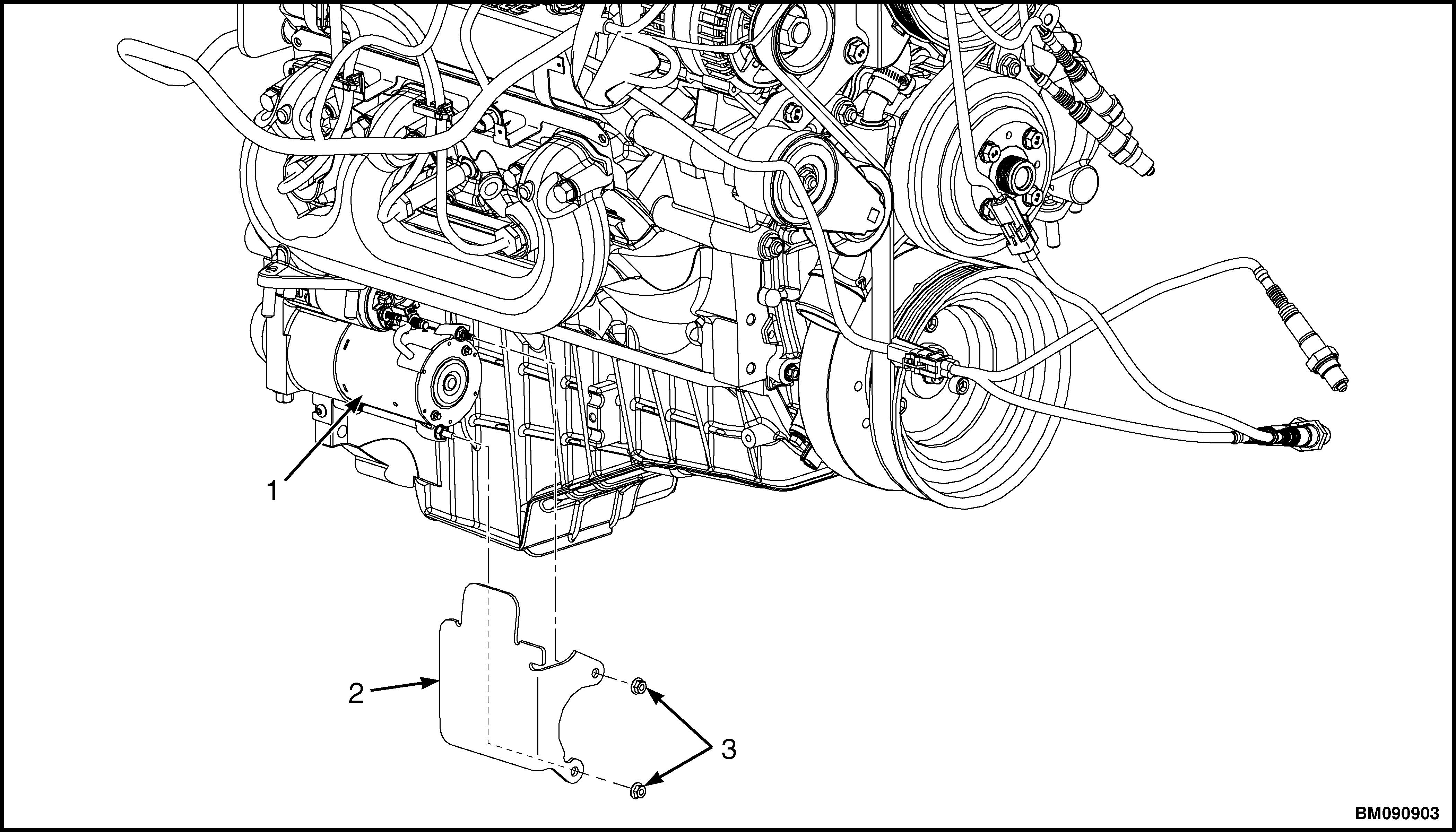
1.STARTER
2.HEAT SHIELD
3.NUT
Starter Replacement 19
Figure 29. Heat Shield
2200 YRM 1097
6. Remove two starter bolts and starter form engine block. See Figure 30.
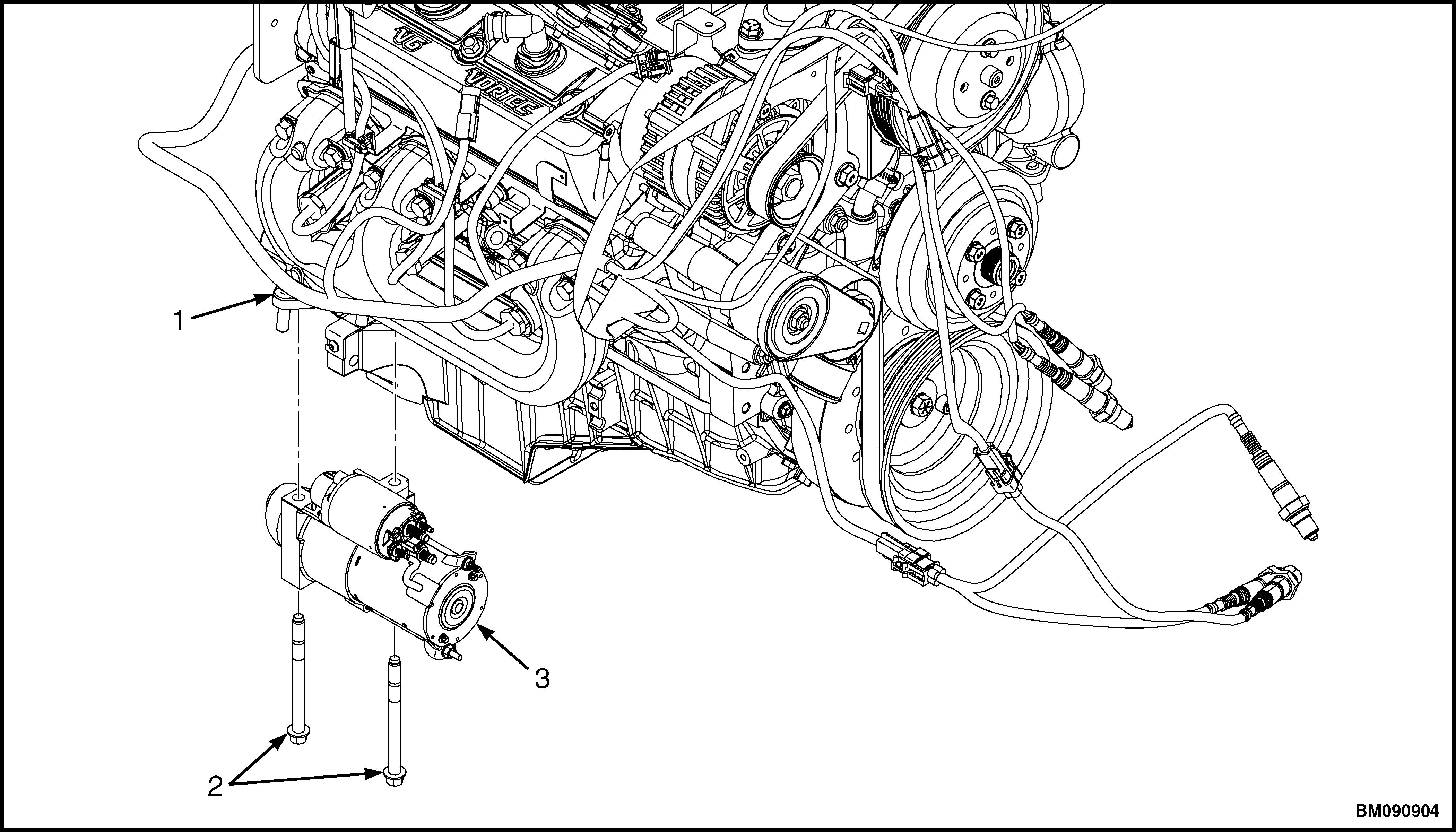
1.ENGINE BLOCK
2.STARTER BOLT
3.STARTER
INSTALL
1. Install starter and two starter bolts on engine block. Tighten bolts to 52 N•m (38 lbf ft). See Figure 30.
2. Install heat shield and two nuts on starter. Tighten nuts to 18 to 24 N•m (159 to 212 lbf in). See Figure 29.
3. Install left side engine mount on engine. Tighten capscrews to 90 N•m (66 lbf ft). See Figure 28.
4. Connect positive (B+) battery cable to starter motor. Tighten terminal nut to 8 to 11 N•m (71 to 97 lbf in). See Figure 28.
5. Install two gaskets, exhaust pipe (5), and two capscrews on exhaust pipe (2). Tighten capscrews to 90 N•m (66 lbf ft). See Figure 27.
6. Install two gaskets, exhaust pipe (5), and three locknuts on exhaust manufold. Tighten capscrews to 39 N•m (29 lbf ft). See Figure 27.
Figure 30. StarterStarter Replacement 2200 YRM 1097 20
Sensors and Switches
GAS AND LPG TRUCKS
Crankshaft Position (CKP) Sensor
Remove
1. Remove the floor mat and floor plate; disconnect the battery for lift truck models
• GLP60-70VX (GP/GLP135-155VX) (C878, D878, E878, F878)
• GLP60-70VX (GLP135-155VX, GP155VXS) (G878)
• GLP80VX, GLP80VX9, GLP90VX (GLP170VX, GLP175VX36, GLP190VX) (A909, B909)
• GLP80VX, GLP80VX9, GLP90VX (C909)
• GLP80VX, GLP80VX9, GLP90VX (D909)
Raise the hood and disconnect the battery for lift truck models
• GC/GLC135-155CA (B879)
• GLC60-70VX (GC/GLC135-155VX) (C879, D879, E879, F879)
• GC070-120LJ/MJ (D818)
• GLC40-55VX; GLC55SVX; (GC/ GLC080-120VX; GC/GLC080-100VXBCS; GC/ GLC120SVX; GC/GLC120VXPRS) (E818, F818)
• GDP60-70CA (GP/GLC/GDP135-155CA (B878)
• GLP/GDP3.5-5.5LJ/MJ (GP/GLP/ GDP70-120LJ/MJ) (E813)
• GLP40VX5/VX6; GLP45SVX5, GLP45VX6, GLP50-55VX (GP/GLP080-120VX ) (F813, G813, H813, J813, K813)
2. Disconnect the crankshaft position (CKP) sensor harness connector. See Figure 31.
3. Remove the CKP sensor mounting bolt. See Figure 32.
4. Remove the CKP sensor. See Figure 33.
Install
CAUTION
When installing the CKP sensor, make sure the sensor is fully seated before tightening the mounting bolt. A poorly seated CKP sensor may perform erratically and may set false DTCs.
NOTE: Do not reuse the original O-ring.
1. Replace the CKP sensor O-ring.
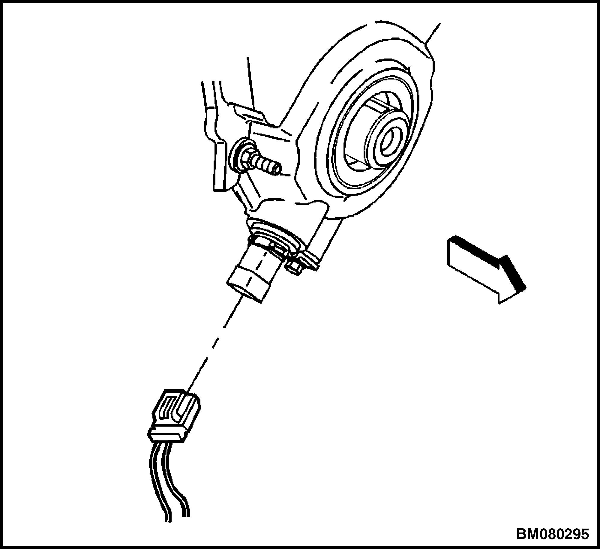
Figure 31. Crankshaft Position (CKP) Sensor Harness
2. Lubricate the O-ring with clean engine oil before installing the CKP sensor.
NOTE: Make sure the CKP sensor mounting surface is clean and free of burrs.
3. Install the CKP sensor. See Figure 33.
CAUTION
Late model engines use a combination of standard and metric fasteners. The components affected are the starter motor, engine mounts, and flywheel housing mounting. Other components may also have a combination of fasteners. Always verify that the proper fasteners are used whenever removing or replacing any components.
4. Install the CKP sensor mounting bolt and tighten the CKP sensor mounting bolt to 9 N•m (80 lbf in). See Figure 32.
5. Connect the CKP sensor harness connector. See Figure 31.
2200 YRM 1097 Sensors and Switches 21
6.
Connect the battery; install floor plate and floor mat for lift truck models
• GLP60-70VX (GC/GLC135-155VX) (C878, D878, E878, F878)
• GLP60-70VX (GLP135-155VX, GP155VXS) (G878)
• GLP80VX, GLP80VX9, GLP90VX (GLP170VX, GLP175VX36, GLP190VX) (A909, B909)
• GLP80VX, GLP80VX9, GLP90VX (C909)
• GLP80VX, GLP80VX9, GLP90VX (D909)
Connect the battery and lower the hood for lift truck models
• GC/GLC/GDC135-155CA (B879)
• GLC/GDC60VX, GLC/GDC70VX (GC/GLC/ GDC135VX, GC/GLC/GDC155VX) (C879, D879, E879, F879)
• GC070-120LJ/MJ (D818)
• GLC40-55VX; GLC55SVX; (GC/ GLC080-120VX; GC/GLC080-100VXBCS; GC/ GLC120SVX; GC/GLC120VXPRS) (E818, F818)
• GDP60-70CA (GP/GLC/GDP135-155CA (B878)
• GLP/GDP3.5-5.5LJ/MJ (GP/GLP/ GDP70-120LJ/MJ) (E813)
• GLP40VX5/VX6; GLP45SVX5, GLP45VX6, GLP50-55VX (GP/GLP080-120VX ) (F813, G813, H813, J813, K813)
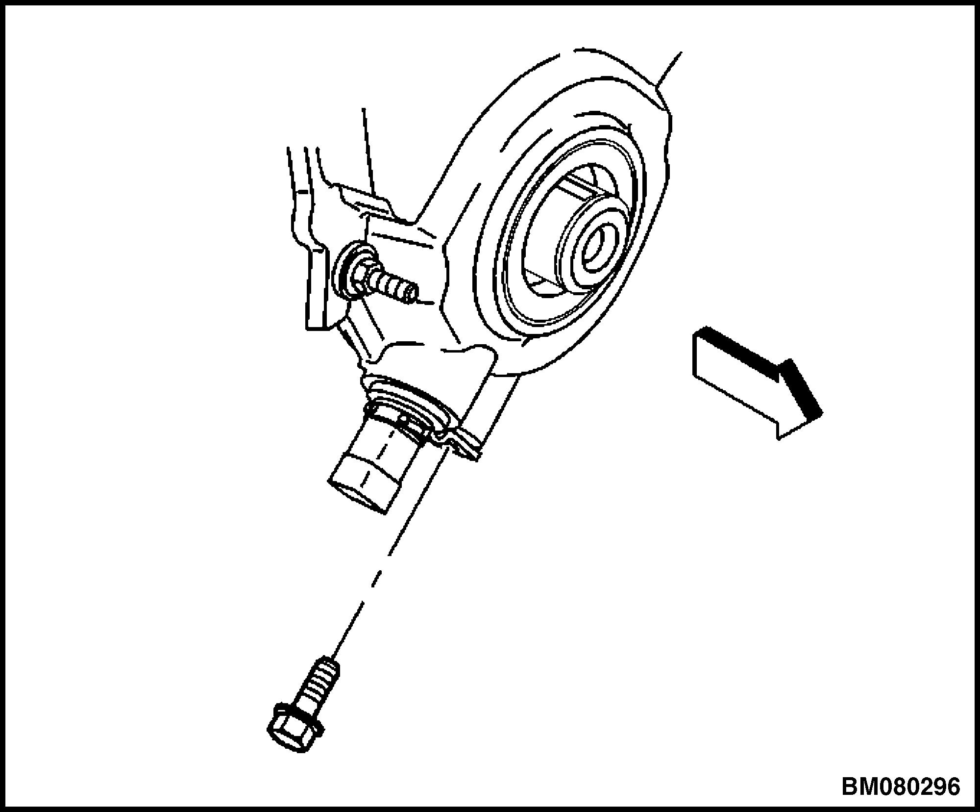
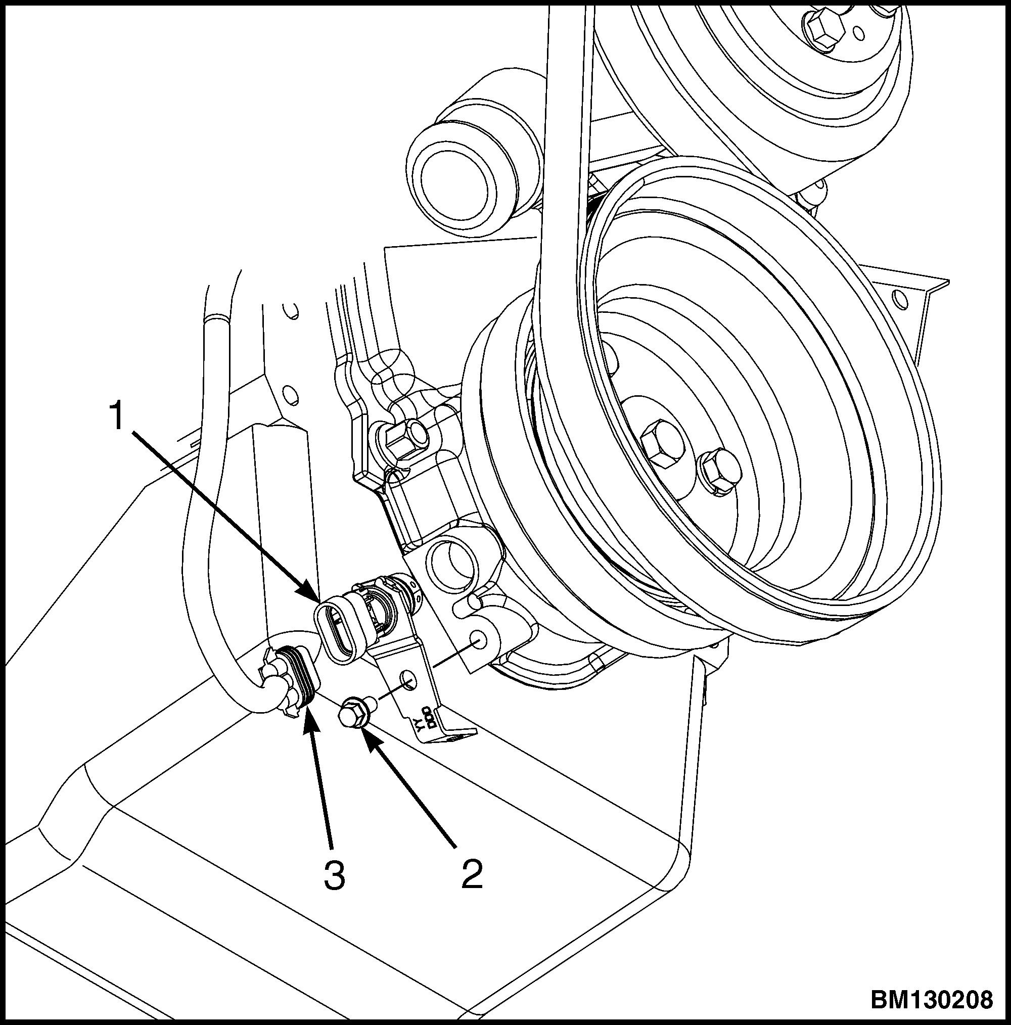
1.CRANKSHAFT POSITION SENSOR
2.MOUNTING BOLT
3.CRANKSHAFT SENSOR HARNESS CONNECTOR
Figure 33. Crankshaft Position (CKP) Sensor Removal/Installation
Camshaft Position (CMP) Sensor
Remove
1. Disconnect the spark plug wires and ignition coil wire from the distributor. Refer to Spark Plug Wire Replacement and Figure 34.
2. Disconnect the camshaft position (CMP) sensor harness connector from the distributor. See Figure 35.
3. Remove the capscrews retaining the distributor cap. Remove the distributor cap. See Figure 36.
4. Remove the rotor retaining screws. See Figure 37.
5. Remove the rotor. See Figure 38.
6. Align the square slot in the reluctor wheel with the CMP sensor. See Figure 39.
Figure 32. Crankshaft Position (CKP) Sensor Mounting BoltSensors and Switches 2200 YRM 1097 22
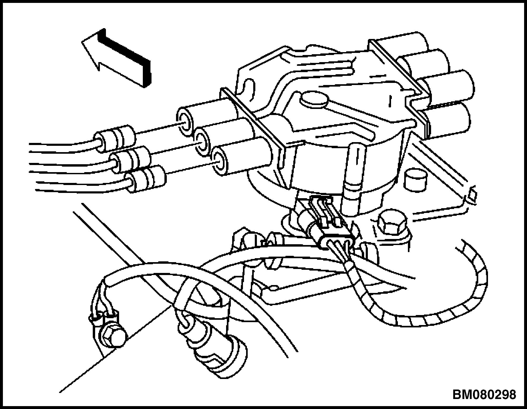
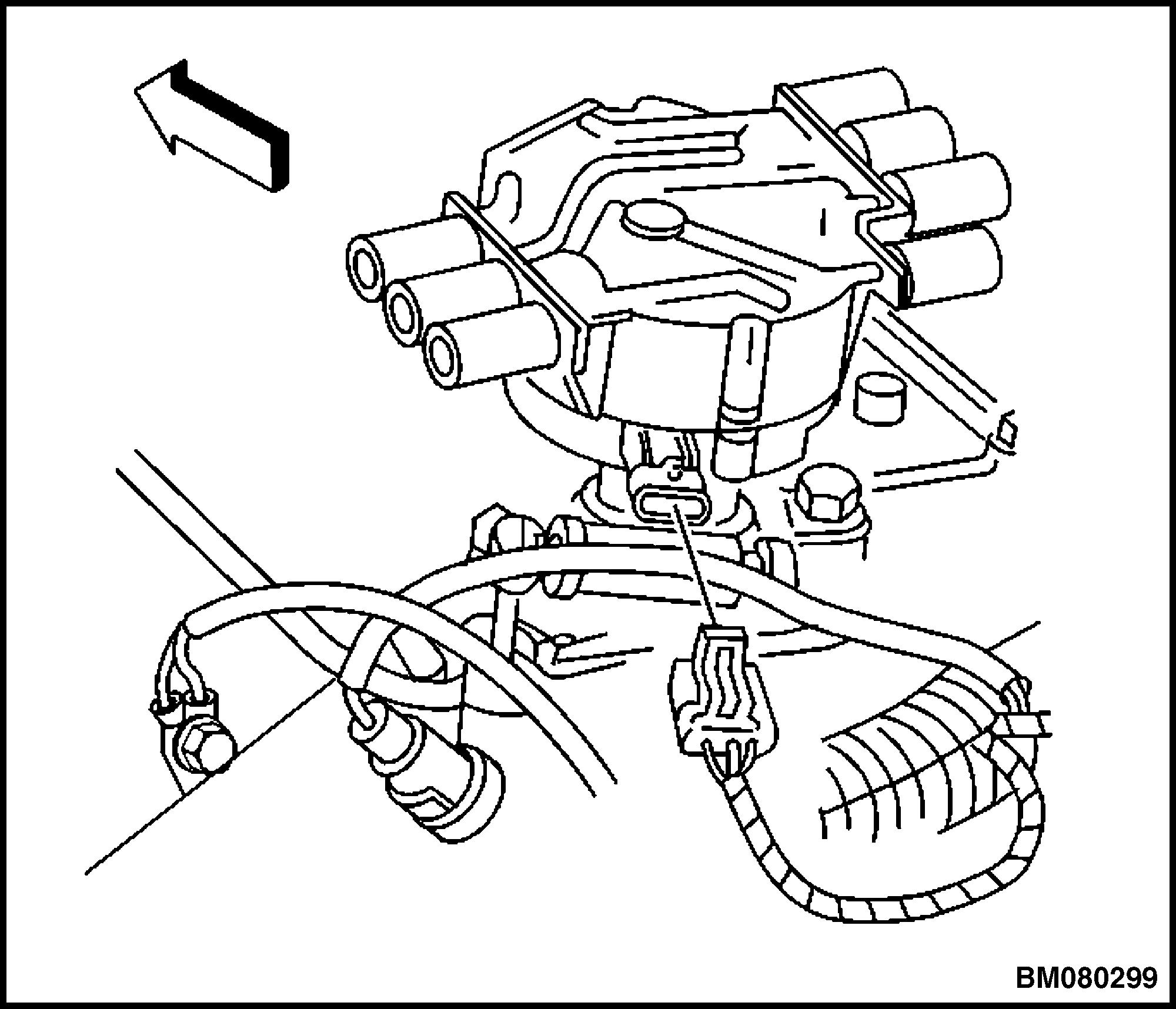
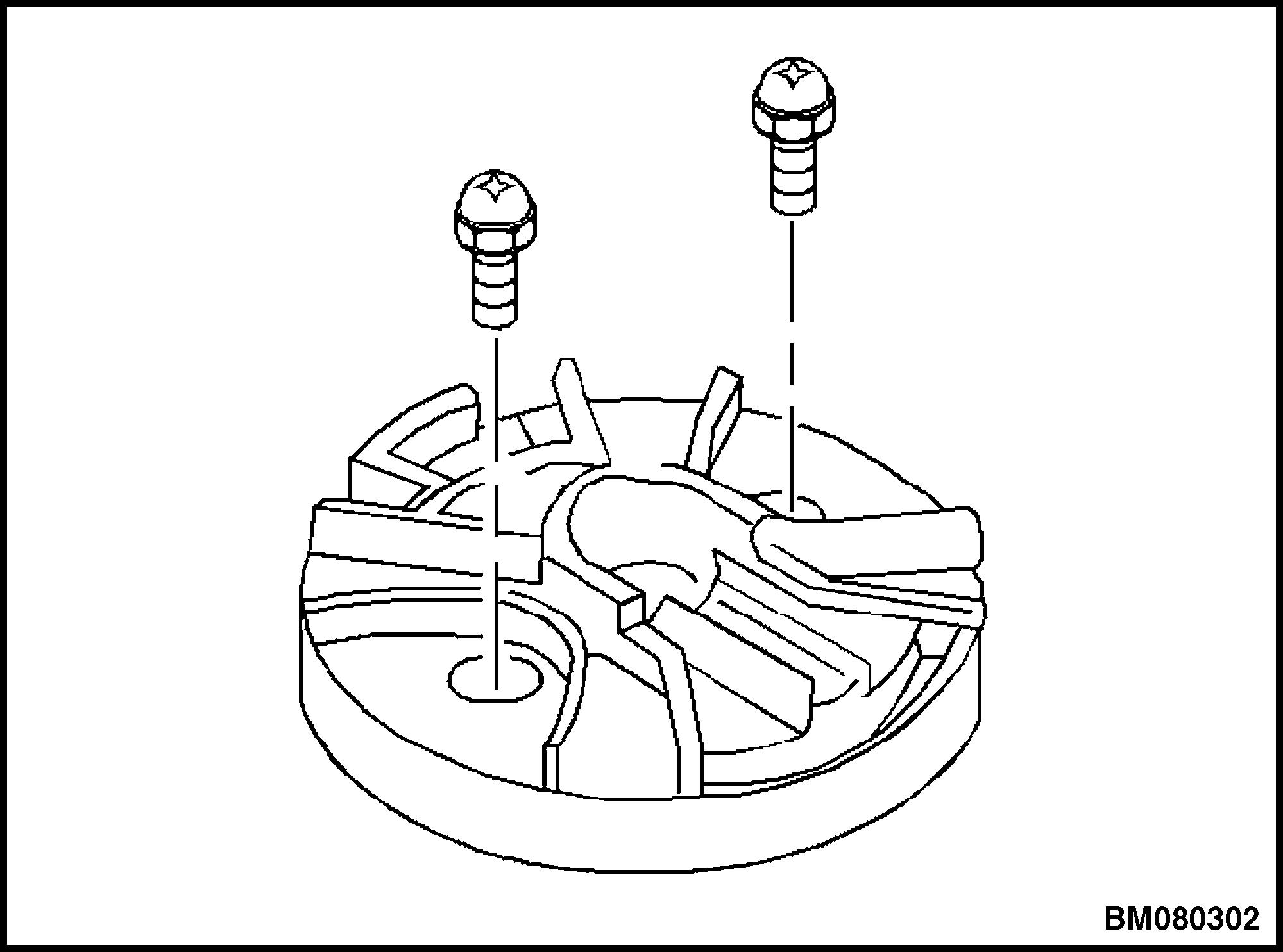 Figure 34. Distributor Cap and Spark Plug Wires
Figure 35. Camshaft Position (CMP) Wire Harness
Figure 36. Distributor Cap Remove/Install
Figure 34. Distributor Cap and Spark Plug Wires
Figure 35. Camshaft Position (CMP) Wire Harness
Figure 36. Distributor Cap Remove/Install
2200 YRM 1097 Sensors and Switches 23
Figure 37. Rotor Retaining Screws
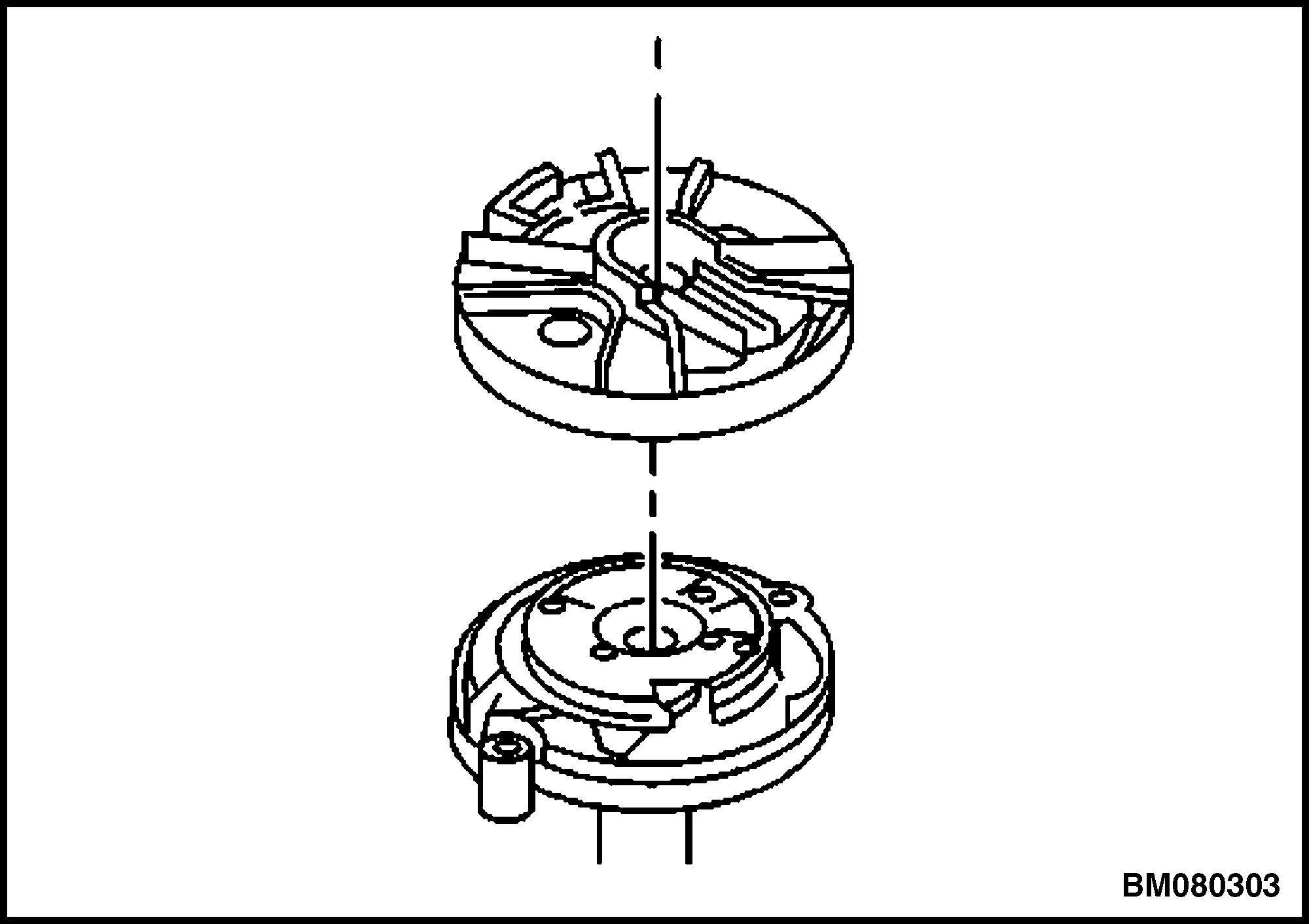
Figure 38. Rotor Remove/Install
Figure 39. Camshaft Position (CMP) Sensor and Reluctor Wheel Alignment
7. Remove the CMP retaining screws. Remove the CMP. See Figure 40.
Install
CAUTION
DO NOT use the old cap, CMP sensor, and rotor screws. Use the replacement screws that have been coated with a thread locking compound.
1. Insert the CMP sensor through the reluctor wheel slot. See Figure 40.
2. Install new CMP mounting screws and tighten to 2.2 N•m (19 lbf in). See Figure 40.
3. Install the rotor onto the reluctor wheel. See Figure 38.
4. Install new rotor retaining screws and tighten to 2 N•m (18 lbf in). See Figure 37.
5. Install the distributor cap and new distributor capscrews. See Figure 36.
6. Connect the CMP sensor harness connector. See Figure 35.
7. Connect the spark plug wires and ignition coil wire. Refer to Spark Plug Wire Replacement and Figure 34.
Figure 40. Camshaft Position Sensor Remove/ Install
Oil Pressure Sensor
Remove
1. Remove the floor mat and floor plate; disconnect the battery for lift truck models
• GLP60-70VX (GC/GLC135-155VX) (C878, D878, E878, F878)
• GLP60-70VX (GLP135-155VX, GP155VXS) (G878)
• GLP80VX, GLP80VX9, GLP90VX (GLP170VX, GLP175VX36, GLP190VX) (A909, B909)
• GLP80VX, GLP80VX9, GLP90VX (C909)
• GLP80VX, GLP80VX9, GLP90VX (D909)
Sensors and Switches 2200 YRM 1097 24
Raise the hood and disconnect the battery for lift truck models
• GC/GLC/GDC135-155CA (B879)
• GLC/GDC60VX, GLC/GDC70VX (GC/GLC/ GDC135VX, GC/GLC/GDC155VX) (C879, D879, E879, F879)
• GC070-120LJ/MJ (D818)
• GLC40-55VX; GLC55SVX; (GC/ GLC080-120VX; GC/GLC080-100VXBCS; GC/ GLC120SVX; GC/GLC120VXPRS) (E818, F818)
• GDP60-70CA (GP/GLC/GDP135-155CA (B878)
• GLP/GDP3.5-5.5LJ/MJ (GP/GLP/ GDP70-120LJ/MJ) (E813)
• GLP40VX5/VX6; GLP45SVX5, GLP45VX6, GLP50-55VX (GP/GLP080-120VX ) (F813, G813, H813, J813, K813)
2. Disconnect the electrical connector for the oil pressure sensor. See Figure 41.
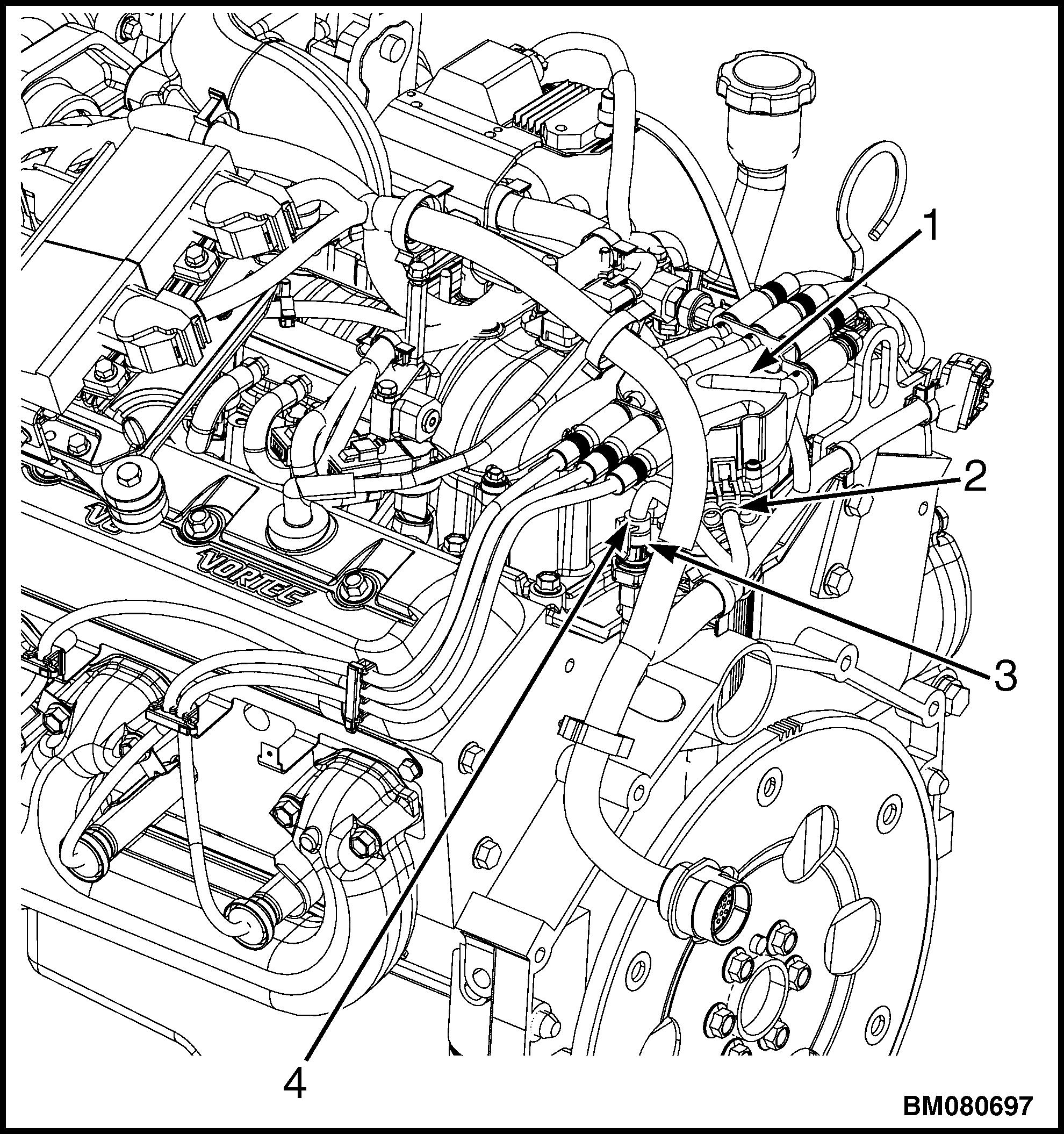
1.DISTRIBUTOR
2.CAMSHAFT POSITION SENSOR
3.OIL PRESSURE SENSOR
4.ELECTRICAL CONNECTOR, OIL PRESSURE SENSOR
Figure 41. Camshaft and Oil Pressure Sensors
3. Remove the oil pressure sensor.
Install
1. Install new oil pressure sensor onto engine. Tighten sensor to 20 N•m (177 lbf in).
2. Connect the electrical connector for the oil pressure sensor. See Figure 41.
3. Connect the battery; install floor plate and floor mat for lift truck models
• GLP60-70VX (GC/GLC135-155VX) (C878, D878, E878, F878
• GLP60-70VX (GLP135-155VX, GP155VXS) (G878)
• GLP80VX, GLP80VX9, GLP90VX (GLP170VX, GLP175VX36, GLP190VX) (A909, B909)
• GLP80VX, GLP80VX9, GLP90VX (C909)
• GLP80VX, GLP80VX9, GLP90VX (D909)
Connect the battery and lower the hood for lift truck models
• GC/GLC/GDC135-155CA (B879)
• GLC/GDC60VX, GLC/GDC70VX (GC/GLC/ GDC135VX, GC/GLC/GDC155VX) (C879, D879, E879, F879)
• GC070-120LJ/MJ (D818)
• GLC40-55VX; GLC55SVX; (GC/ GLC080-120VX; GC/GLC080-100VXBCS; GC/ GLC120SVX; GC/GLC120VXPRS) (E818, F818)
• GDP60-70CA (GP/GLC/GDP135-155CA (B878)
• GLP/GDP3.5-5.5LJ/MJ (GP/GLP/ GDP70-120LJ/MJ) (E813)
• GLP40VX5/VX6; GLP45SVX5, GLP45VX6, GLP50-55VX (GP/GLP080-120VX ) (F813, G813, H813, J813, K813)
2200 YRM 1097 Sensors and Switches 25
Manifold Absolute Pressure (MAP)/ Manifold Air Temperature (MAT) Sensor
Remove
1. Remove the floor mat and floor plate; disconnect the battery for lift truck models
• GLP60-70VX (GC/GLC135-155VX) (C878, D878, E878, F878)
• GLP60-70VX (GLP135-155VX, GP155VXS) (G878)
• GLP80VX, GLP80VX9, GLP90VX (GLP170VX, GLP175VX36, GLP190VX) (A909, B909)
• GLP80VX, GLP80VX9, GLP90VX (C909)
• GLP80VX, GLP80VX9, GLP90VX (D909)
Raise the hood and disconnect the battery for lift truck models
• GC/GLC/GDC135-155CA (B879)
• GLC/GDC60VX, GLC/GDC70VX (GC/GLC/ GDC135VX, GC/GLC/GDC155VX) (C879, D879, E879, F879)
• GC070-120LJ/MJ (D818)
• GLC40-55VX; GLC55SVX; (GC/ GLC080-120VX; GC/GLC080-100VXBCS; GC/ GLC120SVX; GC/GLC120VXPRS) (E818, F818)
• GDP60-70CA (GP/GLC/GDP135-155CA (B878)
• GLP/GDP3.5-5.5LJ/MJ (GP/GLP/ GDP70-120LJ/MJ) (E813)
• GLP40VX5/VX6; GLP45SVX5, GLP45VX6, GLP50-55VX (GP/GLP080-120VX ) (F813, G813, H813, J813, K813)
2. Disconnect the electrical connector from the MAP/MAT sensor. See Figure 42.
3. Remove the nut and MAP/MAT sensor from the intake manifold.
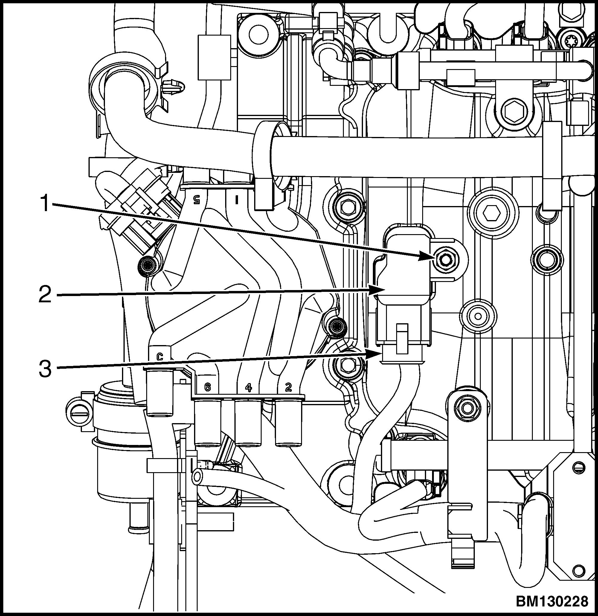
1.RETAINING NUT
2.MAP/MAT SENSOR
3.ELECTRICAL CONNECTOR
Figure 42. MAP/MAT Sensor
Install
1. Place the MAP/MAT sensor in position on the intake manifold and install the retaining nut. Tighten retaining nut to 6 N•m (53 lbf in).
2. Connect the electrical connector to the MAP/MAT sensor. See Figure 42. Verify that the connector clicks/locks into place.
3. Connect the battery; install floor plate and floor mat for lift truck models
• GLP60-70VX (GC/GLC135-155VX) (C878, D878, E878, F878)
• GLP60-70VX (GLP135-155VX, GP155VXS) (G878)
• GLP80VX, GLP80VX9, GLP90VX (GLP170VX, GLP175VX36, GLP190VX) (A909, B909)
• GLP80VX, GLP80VX9, GLP90VX (C909)
• GLP80VX, GLP80VX9, GLP90VX (D909)
Sensors and Switches 2200 YRM 1097 26
Connect the battery and lower the hood for lift truck models
• GC/GLC/GDC135-155CA (B879)
• GLC/GDC60VX, GLC/GDC70VX (GC/GLC/ GDC135VX, GC/GLC/GDC155VX) (C879, D879, E879, F879)
• GC070-120LJ/MJ (D818)
• GLC40-55VX; GLC55SVX; (GC/ GLC080-120VX; GC/GLC080-100VXBCS; GC/ GLC120SVX; GC/GLC120VXPRS) (E818, F818)
• GDP60-70CA (GP/GLC/GDP135-155CA (B878)
• GLP/GDP3.5-5.5LJ/MJ (GP/GLP/ GDP70-120LJ/MJ) (E813)
• GLP40VX5/VX6; GLP45SVX5, GLP45VX6, GLP50-55VX (GP/GLP080-120VX ) (F813, G813, H813, J813, K813)
Engine Coolant Temperature (ECT) Sensor
Remove
1. Remove the floor mat and floor plate; disconnect the battery for lift truck models
• GLP60-70VX (GC/GLC135-155VX) (C878, D878, E878, F878)
• GLP60-70VX (GLP135-155VX, GP155VXS) (G878)
• GLP80VX, GLP80VX9, GLP90VX (GLP170VX, GLP175VX36, GLP190VX) (A909, B909)
• GLP80VX, GLP80VX9, GLP90VX (C909)
• GLP80VX, GLP80VX9, GLP90VX (D909)
Raise the hood and disconnect the battery for lift truck models
• GC/GLC/GDC135-155CA (B879)
• GLC/GDC60VX, GLC/GDC70VX (GC/GLC/ GDC135VX, GC/GLC/GDC155VX) (C879, D879, E879, F879)
• GC070-120LJ/MJ (D818)
• GLC40-55VX; GLC55SVX; (GC/ GLC080-120VX; GC/GLC080-100VXBCS; GC/ GLC120SVX; GC/GLC120VXPRS) (E818, F818)
• GDP60-70CA (GP/GLC/GDP135-155CA (B878)
• GLP/GDP3.5-5.5LJ/MJ (GP/GLP/ GDP70-120LJ/MJ) (E813)
• GLP40VX5/VX6; GLP45SVX5, GLP45VX6, GLP50-55VX (GP/GLP080-120VX ) (F813, G813, H813, J813, K813)
2. Disconnect the electrical connector from the ECT sensor.
See Figure 43 for lift trucks built before January, 2010.
See Figure 44 for lift trucks built after January, 2010.
3. Remove the ECT sensor.
See Figure 43 for lift trucks built before January, 2010.
See Figure 44 for lift trucks built after January, 2010.

1.ELECTRICAL CONNECTOR
2.ECT SENSOR
3.INTAKE MANIFOLD
Figure 43. ECT Sensor for Lift Trucks Built Before January, 2010
2200 YRM 1097 Sensors and Switches 27
CLICK HERE TO DOWNLOAD THE COMPLETE MANUAL
• Thank you very much for reading the preview of the manual.
• You can download the complete manual from: www.heydownloads.com by clicking the link below
• Please note: If there is no response to CLICKING the link, please download this PDF first and then click on it.
CLICK HERE TO DOWNLOAD THE
COMPLETE MANUAL
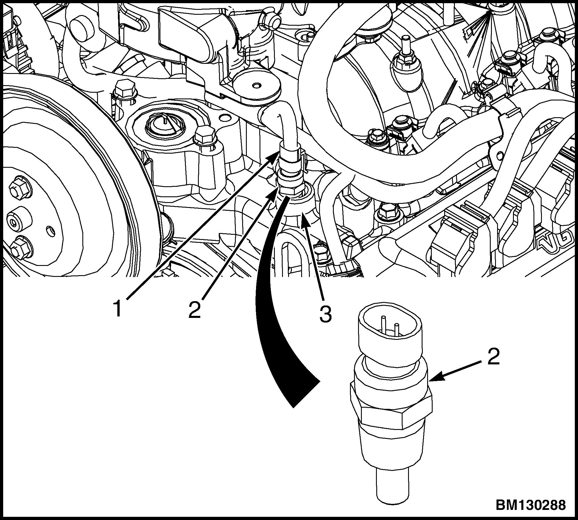
1.ELECTRICAL CONNECTOR
2.ECT SENSOR
3.INTAKE MANIFOLD
Figure 44. ECT Sensor for Lift Trucks Built After January, 2010
Install
1. Install the new ECT sensor. Tighten the sensor to 20 N•m (14.75 lbf ft).
See Figure 43 for lift trucks built before January, 2010.
See Figure 44 for lift trucks built after January, 2010.
2. Connect the electrical connector to the ECT sensor.
See Figure 43 for lift trucks built before January, 2010.
See Figure 44 for lift trucks built after January, 2010.
3. Connect the battery; install floor plate and floor mat for lift truck models
• GLP60-70VX (GC/GLC135-155VX) (C878, D878, E878, F878)
• GLP60-70VX (GLP135-155VX, GP155VXS) (G878)
• GLP80VX, GLP80VX9, GLP90VX (GLP170VX, GLP175VX36, GLP190VX) (A909, B909)
• GLP80VX, GLP80VX9, GLP90VX (C909)
• GLP80VX, GLP80VX9, GLP90VX (D909)
Connect the battery and lower the hood for lift truck models
• GC/GLC/GDC135-155CA (B879)
• GLC/GDC60VX, GLC/GDC70VX (GC/GLC/ GDC135VX, GC/GLC/GDC155VX) (C879, D879, E879, F879)
• GC070-120LJ/MJ (D818)
• GLC40-55VX; GLC55SVX; (GC/ GLC080-120VX; GC/GLC080-100VXBCS; GC/ GLC120SVX; GC/GLC120VXPRS) (E818, F818)
• GDP60-70CA (GP/GLC/GDP135-155CA (B878)
• GLP/GDP3.5-5.5LJ/MJ (GP/GLP/ GDP70-120LJ/MJ) (E813)
• GLP40VX5/VX6; GLP45SVX5, GLP45VX6, GLP50-55VX (GP/GLP080-120VX ) (F813, G813, H813, J813, K813)
Air Flow Restriction Switch
NOTE: The air flow restriction switch is an optional feature on these lift trucks and is a part of the Electronic Monitoring package option.
Remove
1. Remove the floor mat and floor plate; disconnect the battery for lift truck models
• GLP60-70VX (GC/GLC135-155VX) (C878, D878, E878, F878)
• GLP60-70VX (GLP135-155VX, GP155VXS) (G878)
• GLP80VX, GLP80VX9, GLP90VX (GLP170VX, GLP175VX36, GLP190VX) (A909, B909)
• GLP80VX, GLP80VX9, GLP90VX (C909)
• GLP80VX, GLP80VX9, GLP90VX (D909)
Raise the hood and disconnect the battery for lift truck models
• GC/GLC/GDC135-155CA (B879)
• GLC/GDC60VX, GLC/GDC70VX (GC/GLC/ GDC135VX, GC/GLC/GDC155VX) (C879, D879, E879, F879)
• GC070-120LJ/MJ (D818)
• GLC40-55VX; GLC55SVX; (GC/ GLC080-120VX; GC/GLC080-100VXBCS; GC/ GLC120SVX; GC/GLC120VXPRS) (E818, F818)
• GDP60-70CA (GP/GLC/GDP135-155CA (B878)
• GLP/GDP3.5-5.5LJ/MJ (GP/GLP/ GDP70-120LJ/MJ) (E813)
Sensors and Switches 2200 YRM 1097 28
• GLP40VX5/VX6; GLP45SVX5, GLP45VX6, GLP50-55VX (GP/GLP080-120VX ) (F813, G813, H813, J813, K813)
2. Disconnect the air flow restriction switch electrical connection. See Figure 45.
3. Remove air filter restriction switch from air cleaner.
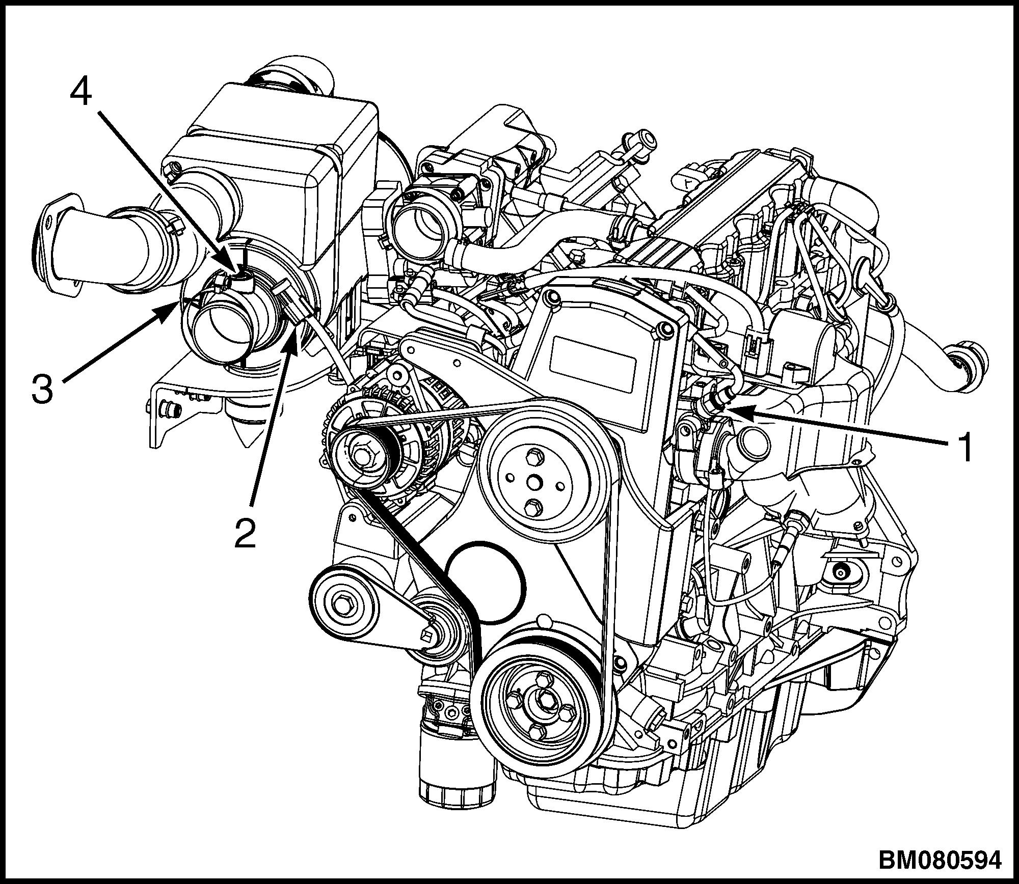
NOTE: AIR CLEANER HOSE NOT SHOWN FOR CLARITY. SWITCH NOT SHOWN, BUT ITEM #4 POINTS TO ITS LOCATION.
1.ECT SENSOR
2.AIR FLOW RESTRICTION ELECTRICAL CONNECTOR
3.AIR CLEANER
4.AIR FLOW RESTRICTION SWITCH
Figure 45. Air Flow Restriction Switch
Install
1. Install new air flow restriction switch into air cleaner.
2. Connect the air flow restriction switch electrical connection. See Figure 45.
3. Connect the battery; install floor plate and floor mat for lift truck models
• GLP60-70VX (GC/GLC135-155VX) (C878, D878, E878, F878)
• GLP60-70VX (GLP135-155VX, GP155VXS) (G878)
• GLP80VX, GLP80VX9, GLP90VX (GLP170VX, GLP175VX36, GLP190VX) (A909, B909)
• GLP80VX, GLP80VX9, GLP90VX (C909)
• GLP80VX, GLP80VX9, GLP90VX (D909)
Connect the battery and lower the hood for lift truck models
• GC/GLC/GDC135-155CA (B879)
• GLC/GDC60VX, GLC/GDC70VX (GC/GLC/ GDC135VX, GC/GLC/GDC155VX) (C879, D879, E879, F879)
• GC070-120LJ/MJ (D818)
• GLC40-55VX; GLC55SVX; (GC/ GLC080-120VX; GC/GLC080-100VXBCS; GC/ GLC120SVX; GC/GLC120VXPRS) (E818, F818)
• GDP60-70CA (GP/GLC/GDP135-155CA (B878)
• GLP/GDP3.5-5.5LJ/MJ (GP/GLP/ GDP70-120LJ/MJ) (E813)
• GLP40VX5/VX6; GLP45SVX5, GLP45VX6, GLP50-55VX (GP/GLP080-120VX ) (F813, G813, H813, J813, K813)
2200 YRM 1097 Sensors and Switches 29
Application
Specifications and Special Tools
Table 1. Ignition System Specifications for GM 4.3L Engines
Firing Order 1-6-5-4-3-2
Spark Plug Wire Resistance 1,000 ohms per ft
Spark Plug Torque 15 N•m (11 lbf ft)
Spark Plug Specifications, GFI LPG Fuel System
B879
C879, D879
R44LTS
C878, D878
E813
F813, G813, H813
D879, E879, F879
E818, F818
R44LTS
D878, E878 AC R44LTS
G813, H813, J813, K813
F878, G878
R44LTS
R44LTS
in.
in.
in.
Specification
Model Spark Plug Type Spark Plug Gap Metric English
AC
0.89 mm 0.035 in.
AC
1.5 mm 0.059 in. D818 AC
0.89 mm 0.035 in. E818, AC
1.5 mm 0.059 in.
AC
0.89 mm 0.035
R44LTS
41-993, 41-101
R44LTS
41-993, 41-101
B878
in.
AC
1.5 mm 0.059
41-993, 41-101
in.
0.89 mm 0.035
AC R44LTS
in.
AC
1.5 mm 0.059 in.
Model Spark Plug Type Spark Plug Gap Metric English
41-993, 41-101
Spark Plug Specifications, PSI LPG Fuel System
AC
0.89 mm 0.035
in.
0.89 mm 0.035
AC R44LTS
in.
0.89
mm 0.035
0.89 mm 0.035
AC
AC
0.89 mm 0.035
Specifications and Special Tools 2200 YRM 1097 30
Table 2. Ignition System Specifications for GM 5.7L Engine Application
Spark Plug Wire Resistance 1225 Ohms per ft. (± 245 Ohms per ft.)
Spark Plug Torque 15 N•m (11 lbf ft)
Spark Plug Specifications
Table 3. Fastener Tightening Specifications
Specification
1-8-4-3-6-5-7-2
Firing Order
Model Spark Plug Type Spark Plug Gap Metric English A909, B909, C909, D909 AC R42LTS 0.89 mm 0.035 in.
Application Specification Metric English Distributor Capscrews 2.4 N•m 21 lbf in Distributor Mounting Clamp Bolt 25 N•m 18 lbf ft Distributor Rotor Retaining Screws 1.9 N•m 17 lbf in Ignition Coil Bracket Stud 11 N•m 97 lbf in Ignition Coil Mounting Screws 11 N•m 97 lbf in Ignition Module Mounting Screws 3.5 N•m 31 lbf in Spark Plug-New Iron Head 30 N•m 22 lbf ft Spark Plug-Used Head 15 N•m 11 lbf ft Engine Mount Capscrews 90 N•m 66 lbf ft Exhaust Lock Nuts 39 N•m 29 lbf ft Starter Heat Shield Nuts 18 to 24 N•m 159 to 212 lbf in Starter Bolts 52 N•m 38 lbf ft 2200 YRM 1097 Specifications and Special Tools 31
Table 4. Special Tools
Illustration
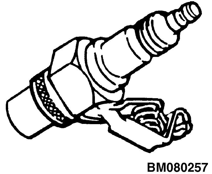
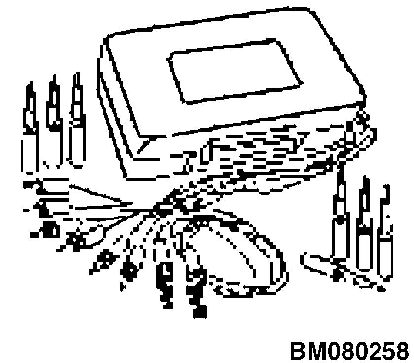
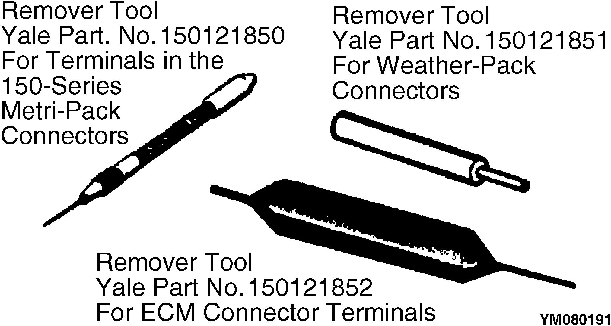
Tool Number/Description
OTC Part No. 7230 Spark Tester
OTC Part No. KMJ35616A Connector Test Adapter Kit
Tool Kit for Terminal Repair Terminals cannot be removed from their connectors nor repaired without special tools. This kit has the special removal and installation tools and crimping tools required to make repairs in Micro-Pack, Metri-Pack, and Weather-Pack connectors. This repair kit does not have the terminals nor the connectors.
Specifications and Special Tools 2200 YRM 1097 32
2200 YRM 1097 3/20 (11/19)(9/15)(4/15)(3/15)(5/14)
DIAGNOSTIC TROUBLESHOOTING MANUAL
GLC20-35VX (GC/GLC040-070VX, GC/ GLC055SVX) [A910];GLP/GDP20-35VX (GP/GLP/ GDP040-070VX) [B875];GC/GLC030VX, GC/GLC035VX, GC/ GLC040SVX [C809];GLP/GDP16VX, GLP/GDP18VX, GLP/ GDP20SVX (GP/GLP/GDP030VX, GP/GLP/GDP035VX, GP/GLP/GDP040SVX) [C810];GLP/GDP60VX, GLP/ GDP70VX (GP/GLP/GDP135VX, GP/GLP/GDP155VX) [C878, D878, E878];GLC/GDC60VX, GLC/GDC70VX (GC/GLC/ GDC135VX, GC/GLC/GDC155VX) [C879, D879, E879, F879];GLC40, 45, 55VX; GLC55SVX (GC/GLC080, 100, 120VX; GC/GLC080, 100VXBCS; GC/GLC120SVX; GC/ GLC120VXPRS) [E818, F818, G818];GLP/GDP40VX5/VX6; GLP/GDP45SVX5, GLP/ GDP45VX6; GLP/ GDP50-55VX (GP/GLP/GDP080, 090, 100, 110, 120VX) [F813, G813, H813, J813, K813];GDP80VX, GDP80VX9, GDP90VX (GDP170VX, GDP175VX36, GDP190VX) [A909, B909, C909];GLP/GDP20VX, 25VS, 30VX, 35VX (GP/GLP/ GDP040VX, 50VX, 60VX, 70VX) [C875];GLC030-035VX, GLC040SVX [D809];GLP/GDP16-18VX, GLP/GDP20SVX (GLP/ GDP030-035VX, GLP/GDP040SVX) [D810];GLC20-35VX (GC/ GLC040-070VX, GC/GLC055SVX) [C910];GLP/GDP20VX, GLP/ GDP25VX, GLP/GDP30VX, GLP/GDP35VX (GP/GLP/ GDP040VX, GP/GLP/GDP050VX, GP/GLP/GDP060VX, GP/GLP/GDP070VX ) [D875];GLP/GDP60-70VX (GLP/ GDP135-155VX) [F878]
Maintenance
PART NO. 524221866 9000 YRM 1112
Safety Precautions TROUBLESHOOTING PROCEDURES
•The Service Manuals are updated on a regular basis, but may not reflect recent design changes to the product. Updated technical service information may be available from your local authorized Yale® dealer. Service Manuals provide general guidelines for maintenance and service and are intended for use by trained and experienced technicians. Failure to properly maintain equipment or to follow instructions contained in the Service Manual could result in damage to the products, personal injury, property damage or death.
•When lifting parts or assemblies, make sure all slings, chains, or cables are correctly fastened, and that the load being lifted is balanced. Make sure the crane, cables, and chains have the capacity to support the weight of the load.
•Do not lift heavy parts by hand, use a lifting mechanism.
•Wear safety glasses.
•DISCONNECT THE BATTERY CONNECTOR before doing any maintenance or repair on electric lift trucks. Disconnect the battery ground cable on internal combustion lift trucks.
•Always use correct blocks to prevent the unit from rolling or falling. See HOW TO PUT THE LIFT TRUCK ON BLOCKS in the Operating Manual or the Periodic Maintenance section.
•Keep the unit clean and the working area clean and orderly.
•Use the correct tools for the job.
•Keep the tools clean and in good condition.
•Always use YALE APPROVED parts when making repairs. Replacement parts must meet or exceed the specifications of the original equipment manufacturer.
•Make sure all nuts, bolts, snap rings, and other fastening devices are removed before using force to remove parts.
•Always fasten a DO NOT OPERATE tag to the controls of the unit when making repairs, or if the unit needs repairs.
•Be sure to follow the WARNING and CAUTION notes in the instructions.
•Gasoline, Liquid Petroleum Gas (LPG), Compressed Natural Gas (CNG), and Diesel fuel are flammable. Be sure to follow the necessary safety precautions when handling these fuels and when working on these fuel systems.
•Batteries generate flammable gas when they are being charged. Keep fire and sparks away from the area. Make sure the area is well ventilated.
NOTE: The following symbols and words indicate safety information in this manual:
WARNING
Indicates a condition that can cause immediate death or injury!
CAUTION
Indicates a condition that can cause property damage!
On the lift truck, the WARNING symbol and word are on orange background. The CAUTION symbol and word are on yellow background.
CLICK HERE TO DOWNLOAD THE COMPLETE MANUAL
• Thank you very much for reading the preview of the manual.
• You can download the complete manual from: www.heydownloads.com by clicking the link below
• Please note: If there is no response to CLICKING the link, please download this PDF first and then click on it.
CLICK HERE TO DOWNLOAD THE
COMPLETE MANUAL
TABLE OF CONTENTS
SECTION 9010 - OPERATIONAL DIAGNOSTIC PROCEDURES
Group 05 - Operational Checkout ...........................................................................................................9010-05-1
SECTION 9020 - ENGINE
Group 10 - Principles of Operation .........................................................................................................9020-10-1
Group 30 - Observed Symptoms ............................................................................................................9020-30-1
Group 40 - Tests and Adjustments .........................................................................................................9020-40-1
SECTION 9030 - ELECTRICAL SYSTEM
Group 03 - General Maintenance and Diagnostic Data ..........................................................................9030-03-1
Diagnostic Trouble Code (DTC) Chart.................................................................................................9030-03-7
Group 10 - Principles of Operation .........................................................................................................9030-10-1
Group 20 - Diagnostic Trouble Codes ....................................................................................................9030-20-1
Group 30 - Observed Symptoms ............................................................................................................9030-30-1
SECTION 9040 - DRIVE TRAIN
Group 10 - Principles of Operation .........................................................................................................9040-10-1
Group 30 - Observed Symptoms ............................................................................................................9040-30-1
Group 40 - Tests and Adjustments .........................................................................................................9040-40-1
SECTION 9050 - HYDRAULIC SYSTEMS
Group 10 - Principles of Operation .........................................................................................................9050-10-1
Group 30 - Observed Symptoms ............................................................................................................9050-30-1
Group 33 - Observed Symptoms-Gear Pump ........................................................................................9050-33-1
Group 35 - Observed Symptoms-Variable Displacement Pump (VDP) ..................................................9050-35-1
Group 40 - Tests and Adjustments .........................................................................................................9050-40-1
Group 43 - Tests and Adjustments-Gear Pump ......................................................................................9050-43-1
Group 45 - Tests and Adjustments-Variable Displacement Pump (VDP) ...............................................9050-45-1
SECTION 9060 - OPERATORS STATION
Group 10 - Principles of Operation .........................................................................................................9060-10-1
SECTION 9070 - FRONT END (MAST) AND CHASSIS
Group 10 - Principles of Operation .........................................................................................................9070-10-1
Group 30 - Observed Symptoms ............................................................................................................9070-30-1
SECTION 9080 - SUPPLEMENTARY DATA
Group 50 - Abbreviations and Acronyms ................................................................................................9080-50-1
Group 60 - Special Tools List ..................................................................................................................9080-60-1
Group 70 - Fault Mode Indicator Reference ...........................................................................................9080-70-1
Group 80 - Supplier Specification Data ..................................................................................................9080-80-1
©2020 Yale Materials Handling Corp.
Diagnostic Troubleshooting ManualTable of Contents i
This section is for the following models:
GLC20-35VX (GC/GLC040-070VX, GC/GLC055SVX) [A910]; GLP/GDP20-35VX (GP/GLP/GDP040-070VX) [B875]; (GC/GLC030VX, GC/GLC035VX, GC/GLC040SVX) [C809]; GLP/GDP16VX, GLP/GDP18VX, GLP/GDP20SVX (GP/GLP/GDP030VX, GP/GLP/ GDP035VX, GP/GLP/GDP040SVX) [C810];
GLP/GDP60VX, GLP/GDP70VX (GP/GLP/GDP135VX, GP/GLP/GDP155VX) [C878, D878, E878];
GLC/GDC60VX, GLC/GDC70VX (GC/GLC/GDC135VX, GC/GLC/GDC155VX) [C879, D879, E879, F879];
GLC40, 45, 55VX; GLC55SVX (GC/GLC080, 100, 120VX; GC/GLC080, 100VXBCS; GC/GLC120SVX; GC/GLC120VXPRS) [E818, F818, G818];
GLP/GDP40VX5/VX6; GLP/GDP45SVX5, GLP/ GDP45VX6; GLP/GDP50-55VX (GP/GLP/GDP080, 090, 100, 110, 120VX) [F813, G813, H813, J813, K813];
GDP80VX, GDP80VX9, GDP90VX (GDP170VX, GDP175VX36, GDP190VX) [A909, B909, C909];
GLP/GDP20VX, 25VS, 30VX, 35VX (GP/GLP/GDP040VX, 50VX, 60VX, 70VX) [C875]; (GLC030-035VX, GLC040SVX) [D809];
GLP/GDP16-18VX, GLP/GDP20SVX (GLP/GDP030-035VX, GLP/GDP040SVX) [D810]; GLC20-35VX (GC/GLC040-070VX, GC/GLC055SVX) [C910]; GLP/GDP20VX, GLP/GDP25VX, GLP/GDP30VX, GLP/GDP35VX (GP/GLP/ GDP040VX, GP/GLP/GDP050VX, GP/GLP/GDP060VX, GP/GLP/GDP070VX ) [D875];
GLP/GDP60-70VX (GLP/GDP135-155VX) [F878]
Table of ContentsDiagnostic Troubleshooting Manual ii
How To Use This Troubleshooting Manual
GENERAL INSTRUCTIONS AND SAFETY INFORMATION
WARNING
DO NOT add to or modify the lift truck. Any modification that affects the safe operation of the truck cannot be undertaken without written authorization of the Yale company.
Any change to the lift truck, the tires, or its equipment can change the lifting capacity. The lift truck must be rated as equipped and the nameplate must show the new rating capacity.
WARNING
The technician must be aware of, and follow, all general safety precautions that are published in the Operating Manual and that are posted as Safety Decals on and in the lift truck.
Before starting, the technician should be familiar with certain policies, requirements, and instructions used in the troubleshooting procedures. Using the troubleshooting procedures correctly helps the technician to perform the procedure safely and prevents damage to the machine and support equipment.
HOW TO USE DIAGNOSTIC TROUBLESHOOTING MANUAL
Manual Layout:
Sections: The manual is divided into nine sections, each representing a major system, functional area, or specific operation on the lift truck.
•9010 – Operational Diagnostic Procedures
•9020 – Engine
•9030 – Electrical System
•9040 – Powertrain
•9050 – Hydraulic Systems
•9060 – Operator's Station
•9070 – Front End (Mast) and Chassis
•9080 – Supplementary Data
Groups: The sections of the manual are further subdivided into groups, where applicable, that identify specific functions, operating criteria, or maintenance tasks.
•01 – Introduction to the Troubleshooting Manual
•03 – General Maintenance/Diagnostic Data
•05 – Operational Checkout
•10 – Principles of Operation
•20 – Diagnostic Trouble Codes
•30 – Observed Symptoms
•40 – Test and Adjustments
NOTE: Not all groups will appear in all sections.
Supplementary Data: The supplementary data section of the manual includes information and data that apply to many sections or groups and is stored here for access by all users of the manual. This data includes, but is not limited to:
•Abbreviations and Acronyms
•Special Tools List
•Fault Mode Indication Reference Table
•Supplier Specification Data
Diagnostic Troubleshooting ManualHow To Use This Troubleshooting Manual Check the Service Manual section in Yale Axcess Online for possible updates and check pertinent Bulletins Confidential/Proprietary - Do Not Copy or Duplicate iii
GENERAL INSTRUCTIONS
1Become familiar with the content, layout, and access provisions of data in this manual. This will improve your efficiency and decrease the time required to resolve the problems.
2Use all sections of the manual for relevant information on the subject system.
3Once you begin a troubleshooting procedure, do not skip steps.
4If you reach the end of a procedure without resolving the problem and you are not directed to another procedure contact Resident Service Engineering through the Contact Management System.
5Do not limit yourself, remember to apply your own experience and knowledge to assist in resolving the problems, but do not compromise safety in doing so.
6Most of the cross-reference data in the manual will be electronically linked for rapid and easy access. Use the links wherever the cursor highlights an item as a linkable option.
As an example of this linking option:
Assume that during a procedure or test, it is necessary to refer to a different section of manual, in this case, the Light Circuit Check in the Operational Checkout part of this manual.
The instruction would read, "refer to, or see" followed by text identifying what the reference is (for hard-copy, paper manual use). When the cursor is placed over the text, it will then indicate that it is active, and left-clicking will direct the system to take you directly to that reference.
How To Use This Troubleshooting ManualDiagnostic Troubleshooting Manual Check the Service Manual section in Yale Axcess Online for possible updates and check pertinent Bulletins iv Confidential/Proprietary - Do Not Copy or Duplicate
Service Manual Lookup
The following service manuals are referenced throughout this manual. Be sure to have the correct service manual for your lift truck model.
Alternator With Regulator 2200YRM0002
•GLC20-35VX (GC/GLC040-070VX,GC/ GLC055SVX) (A910)
•GLP/GDP20-35VX (GP/GLP/GDP040-070VX) (B875)
Brake System 1800YRM1135
•GC/GLC040SVX (C809)
•GLP/GDP16VX, GLP/GDP18VX, GLP/ GDP20SVX (GP/GLP/GDP030VX, GP/GLP/ GDP035VX, GP/GLP/GDP040SVX) (C810)
•GLC20-35VX (GC/GLC040-070VX,GC/ GLC055SVX) (A910)
•GLP/GDP20-35VX (GP/GLP/GDP040-070VX) (B875)
Brake System - DANA 1800YRM1247
•GLC40, 45, 55VX;GLC55SVX; (GC/GLC080, 100, 120VX; GC/GLC080, 100VXBCS; GC/ GLC120SVX; GC/GLC120VXPRS) (E818)
•GLP/GDP40VX5/VX6; GLP/GDP45SVX5,GLP/ GDP45VX6, GLP/GDP50-55VX (GP/GLP/ GDP080, 090, 100, 110, 120VX) (F813, G813, H813)
•GLC/GDC60VX, GLC/GDC70VX (GC/GLC/ GDC135VX, GC/GLC/GDC155VX) (C879, D879, E879, F879)
•GLP/GDP60VX, GLP/GDP70VX (GP/GLP/ GDP135VX, GP/GLP/GDP155VX) (C878, D878, E878)
•GLP/GDP80VX, GLP/GDP80VX9, GLP/ GDP90VX (GLP/GDP170VX, GLP/ GDP175VX36,GLP/GDP190VX) (A909, B909)
Calibration Procedures 8000YRM1134
ALL LIFT TRUCKS
Capacities and Specifications 8000YRM1751
•GLC030-035VX, GLC040SVX (D809); GLP16-18VX, GLP20SVX (GLP030-035VX, GLP040SVX) (D810)
Capacities and Specifications 8000YRM1151
•GLC20-35VX (GC/GLC040-070VX,GC/ GLC055SVX) (A910)
•GLP/GDP20-35VX (GP/GLP/GDP040-070VX) (B875)
Capacities and Specifications 8000YRM1208
•GC/GLC040SVX (C809)
•GLP/GDP16VX, GLP/GDP18VX, GLP/ GDP20SVX (GP/GLP/GDP030VX, GP/GLP/ GDP035VX, GP/GLP/GDP040SVX) (C810)
Capacities and Specifications 8000YRM1249
•GLC40, 45, 55VX;GLC55SVX; (GC/GLC080, 100, 120VX; GC/GLC080, 100VXBCS; GC/ GLC120SVX; GC/GLC120VXPRS) (E818)
•GLP/GDP40VX5/VX6; GLP/GDP45SVX5,GLP/ GDP45VX6, GLP/GDP50-55VX (GP/GLP/ GDP080, 090, 100, 110, 120VX) (F813, G813)
Capacities and Specifications 8000YRM1320
•GLC/GDC60VX, GLC/GDC70VX (GC/GLC/ GDC135VX, GC/GLC/GDC155VX) (C879, D879)
•GLP/GDP60VX, GLP/GDP70VX (GP/GLP/ GDP135VX, GP/GLP/GDP155VX) (C878, D878)
Capacities and Specifications 8000YRM1408
•GLP/GDP80VX, GLP/GDP80VX9, GLP/ GDP90VX (GLP/GDP170VX, GLP/ GDP175VX36,GLP/GDP190VX) (A909)
Capacities and Specifications 8000YRM1559
•GLP/GDP40VX5/VX6; GLP/GDP45SVX5,GLP/ GDP45VX6, GLP/GDP50-55VX (GP/GLP/ GDP080, 090, 100, 110, 120VX) (H813)
Capacities and Specifications 8000YRM1572
•GLC/GDC60VX, GLC/GDC70VX (GC/GLC/ GDC135VX, GC/GLC/GDC155VX) (E879)
Capacities and Specifications 8000YRM1584
•GLP/GDP60VX, GLP/GDP70VX (GP/GLP/ GDP135VX, GP/GLP/GDP155VX) (E878)
Capacities and Specifications 8000YRM1587
•GLP/GDP80VX, GLP/GDP80VX9, GLP/ GDP90VX (GLP/GDP170VX, GLP/ GDP175VX36,GLP/GDP190VX) (B909)
Capacities and Specifications 8000YRM1599
•GLC40, 45, 55VX;GLC55SVX; (GC/GLC080, 100, 120VX; GC/GLC080, 100VXBCS; GC/ GLC120SVX; GC/GLC120VXPRS) (F818)
Capacities and Specifications 8000YRM1605
•GLP/GDP40VX5/VX6; GLP/GDP45SVX5,GLP/ GDP45VX6, GLP/GDP50-55VX (GP/GLP/ GDP080, 090, 100, 110, 120VX) (H813)
Capacities and Specifications 8000YRM1607
•GLC/GDC60VX, GLC/GDC70VX (GC/GLC/ GDC135VX, GC/GLC/GDC155VX) (F879)
Diagnostic Troubleshooting ManualService Manual Lookup Check the Service Manual section in Yale Axcess Online for possible updates and check pertinent Bulletins Confidential/Proprietary - Do Not Copy or Duplicate v
Cooling System 0700YRM1123
•GC/GLC040SVX (C809)
•GLP/GDP16VX, GLP/GDP18VX, GLP/ GDP20SVX (GP/GLP/GDP030VX, GP/GLP/ GDP035VX, GP/GLP/GDP040SVX) (C810)
•GLC20-35VX (GC/GLC040-070VX,GC/ GLC055SVX) (A910)
•GLP/GDP20-35VX (GP/GLP/GDP040-070VX) (B875)
•GLC40, 45, 55VX;GLC55SVX; (GC/GLC080, 100, 120VX; GC/GLC080, 100VXBCS; GC/ GLC120SVX; GC/GLC120VXPRS) (E818, F818)
•GLP/GDP40VX5/VX6; GLP/GDP45SVX5,GLP/ GDP45VX6, GLP/GDP50-55VX (GP/GLP/ GDP080, 090, 100, 110, 120VX) (F813, G813, H813, J813)
•GLC/GDC60VX, GLC/GDC70VX (GC/GLC/ GDC135VX, GC/GLC/GDC155VX) (C879, D879, E879, F879)
•GLP/GDP60VX, GLP/GDP70VX (GP/GLP/ GDP135VX, GP/GLP/GDP155VX) (C878, D878, E878)
•GLP/GDP80VX, GLP/GDP80VX9, GLP/ GDP90VX (GLP/GDP170VX, GLP/ GDP175VX36,GLP/GDP190VX) (A909, B909)
Cylinder Repair (Mast S/N A551, A555, A559, A661, A662, A663, A66, B507, B508, B509, B551, B555, B559, B562, B563, B564, B661, B662, B663, C515, C551, C555, C559, D507, D508, D509, D515, D562, D563, D564, E509, and E564) 2100YRM1139
•GC/GLC040SVX (C809)
•GLP/GDP16VX, GLP/GDP18VX, GLP/ GDP20SVX (GP/GLP/GDP030VX, GP/GLP/ GDP035VX, GP/GLP/GDP040SVX) (C810)
•GLC20-35VX (GC/GLC040-070VX,GC/ GLC055SVX) (A910)
•GLP/GDP20-35VX (GP/GLP/GDP040-070VX) (B875)
•GLC40, 45, 55VX;GLC55SVX; (GC/GLC080, 100, 120VX; GC/GLC080, 100VXBCS; GC/ GLC120SVX; GC/GLC120VXPRS) (E818, F818)
•GLP/GDP40VX5/VX6; GLP/GDP45SVX5,GLP/ GDP45VX6, GLP/GDP50-55VX (GP/GLP/ GDP080, 090, 100, 110, 120VX) (F813, G813, H813, J813)
Cylinder Repair (Mast S/N A513, A514, A613, A614, B513, B514) 2100YRM1328
•GLC/GDC60VX, GLC/GDC70VX (GC/GLC/ GDC135VX, GC/GLC/GDC155VX) (C879, D879, E879, F879)
•GLP/GDP60VX, GLP/GDP70VX (GP/GLP/ GDP135VX, GP/GLP/GDP155VX) (C878, D878, E878)
•GLP/GDP80VX, GLP/GDP80VX9, GLP/ GDP90VX (GLP/GDP170VX, GLP/ GDP175VX36,GLP/GDP190VX) (A909, B909)
Diagrams and Schematics 8000YRM1152
•GC/GLC040SVX (C809)
•GLP/GDP16VX, GLP/GDP18VX, GLP/ GDP20SVX (GP/GLP/GDP030VX, GP/GLP/ GDP035VX, GP/GLP/GDP040SVX) (C810)
•GLC20-35VX (GC/GLC040-070VX,GC/ GLC055SVX) (A910)
•GLP/GDP20-35VX (GP/GLP/GDP040-070VX) (B875)
•GLC40, 45, 55VX;GLC55SVX; (GC/GLC080, 100, 120VX; GC/GLC080, 100VXBCS; GC/ GLC120SVX; GC/GLC120VXPRS) (E818)
•GLP/GDP40VX5/VX6; GLP/GDP45SVX5,GLP/ GDP45VX6, GLP/GDP50-55VX (GP/GLP/ GDP080, 090, 100, 110, 120VX) (F813)
•GLC/GDC60VX, GLC/GDC70VX (GC/GLC/ GDC135VX, GC/GLC/GDC155VX) (C879)
•GLP/GDP60VX, GLP/GDP70VX (GP/GLP/ GDP135VX, GP/GLP/GDP155VX) (C878)
Diagrams and Schematics 8000YRM1387
•GC/GLC040SVX (C809)
•GLP/GDP16VX, GLP/GDP18VX, GLP/ GDP20SVX (GP/GLP/GDP030VX, GP/GLP/ GDP035VX, GP/GLP/GDP040SVX) (C810)
•GLC40, 45, 55VX;GLC55SVX; (GC/GLC080, 100, 120VX; GC/GLC080, 100VXBCS; GC/ GLC120SVX; GC/GLC120VXPRS) (E818)
•GLP/GDP40VX5/VX6; GLP/GDP45SVX5,GLP/ GDP45VX6, GLP/GDP50-55VX (GP/GLP/ GDP080, 090, 100, 110, 120VX) (F813, G813)
•GLC/GDC60VX, GLC/GDC70VX (GC/GLC/ GDC135VX, GC/GLC/GDC155VX) (D879)
•GLP/GDP60VX, GLP/GDP70VX (GP/GLP/ GDP135VX, GP/GLP/GDP155VX) (D878)
Diagrams and Schematics 8000YRM1409
•GC/GLC040SVX (C809)
•GLP/GDP16VX, GLP/GDP18VX, GLP/ GDP20SVX (GP/GLP/GDP030VX, GP/GLP/ GDP035VX, GP/GLP/GDP040SVX) (C810)
•GLC40, 45, 55VX;GLC55SVX; (GC/GLC080, 100, 120VX; GC/GLC080, 100VXBCS; GC/ GLC120SVX; GC/GLC120VXPRS) (E818)
•GLP/GDP40VX5/VX6; GLP/GDP45SVX5,GLP/ GDP45VX6, GLP/GDP50-55VX (GP/GLP/ GDP080, 090, 100, 110, 120VX) (G813)
Service Manual LookupDiagnostic Troubleshooting Manual Check the Service Manual section in Yale Axcess Online for possible updates and check pertinent Bulletins vi Confidential/Proprietary - Do Not Copy or Duplicate
•GLC20-35VX (GC/GLC040-070VX,GC/ GLC055SVX) (A910)
•GLP/GDP20-35VX (GP/GLP/GDP040-070VX) (B875)
Frame 0100YRM1243
•GLC40, 45, 55VX;GLC55SVX; (GC/GLC080, 100, 120VX; GC/GLC080, 100VXBCS; GC/ GLC120SVX; GC/GLC120VXPRS) (E818, F818)
•GLP/GDP40VX5/VX6; GLP/GDP45SVX5,GLP/ GDP45VX6, GLP/GDP50-55VX (GP/GLP/ GDP080, 090, 100, 110, 120VX) (F813, G813, H813, J813)
Frame 0100YRM1316
•GLC/GDC60VX, GLC/GDC70VX (GC/GLC/ GDC135VX, GC/GLC/GDC155VX) (C879, D879, E879, F879)
Frame 0100YRM1321
•GLP/GDP60VX, GLP/GDP70VX (GP/GLP/ GDP135VX, GP/GLP/GDP155VX) (C878, D878)
•GLP/GDP80VX, GLP/GDP80VX9, GLP/ GDP90VX (GLP/GDP170VX, GLP/ GDP175VX36,GLP/GDP190VX) (A909)
Frame 0100YRM1581
•GLP/GDP60VX, GLP/GDP70VX (GP/GLP/ GDP135VX, GP/GLP/GDP155VX) (E878)
•GLP/GDP80VX, GLP/GDP80VX9, GLP/ GDP90VX (GLP/GDP170VX, GLP/ GDP175VX36,GLP/GDP190VX) (B909)
Gasoline Fuel System 0900YRM1127
•GC/GLC040SVX (C809)
•GLP/GDP16VX, GLP/GDP18VX, GLP/ GDP20SVX (GP/GLP/GDP030VX, GP/GLP/ GDP035VX, GP/GLP/GDP040SVX) (C810)
•GLC20-35VX (GC/GLC040-070VX,GC/ GLC055SVX) (A910)
•GLP/GDP20-35VX (GP/GLP/GDP040-070VX) (B875)
Gasoline Fuel System 0900YRM1244
•GLC40, 45, 55VX;GLC55SVX; (GC/GLC080, 100, 120VX; GC/GLC080, 100VXBCS; GC/ GLC120SVX; GC/GLC120VXPRS) (E818)
•GLP/GDP40VX5/VX6; GLP/GDP45SVX5,GLP/ GDP45VX6, GLP/GDP50-55VX (GP/GLP/ GDP080, 090, 100, 110, 120VX) (F813, G813)
•GLC/GDC60VX, GLC/GDC70VX (GC/GLC/ GDC135VX, GC/GLC/GDC155VX) (C879, D879)
•GLP/GDP60VX, GLP/GDP70VX (GP/GLP/ GDP135VX, GP/GLP/GDP155VX) (C878, D878)
Gasoline Fuel System 0900YRM1325
•GC/GLC040SVX (C809)
•GLP/GDP16VX, GLP/GDP18VX, GLP/ GDP20SVX (GP/GLP/GDP030VX, GP/GLP/ GDP035VX, GP/GLP/GDP040SVX) (C810)
•GLP/GDP20-35VX (GP/GLP/GDP040-070VX) (B875)
Gasoline Fuel System PSI GM 4.3L 0900YRM1570
•GLC40, 45, 55VX;GLC55SVX; (GC/GLC080, 100, 120VX; GC/GLC080, 100VXBCS; GC/ GLC120SVX; GC/GLC120VXPRS) (E818, F818)
•GLP/GDP40VX5/VX6; GLP/GDP45SVX5,GLP/ GDP45VX6, GLP/GDP50-55VX (GP/GLP/ GDP080, 090, 100, 110, 120VX) (H813, J813)
•GLC/GDC60VX, GLC/GDC70VX (GC/GLC/ GDC135VX, GC/GLC/GDC155VX) (E879, F879)
•GLP/GDP60VX, GLP/GDP70VX (GP/GLP/ GDP135VX, GP/GLP/GDP155VX) (D878, E878)
GM 4.3L V-6 Engines 0600YRM1251
•GLC40, 45, 55VX;GLC55SVX; (GC/GLC080, 100, 120VX; GC/GLC080, 100VXBCS; GC/ GLC120SVX; GC/GLC120VXPRS) (E818, F818)
•GLP/GDP40VX5/VX6; GLP/GDP45SVX5,GLP/ GDP45VX6, GLP/GDP50-55VX (GP/GLP/ GDP080, 090, 100, 110, 120VX) (F813, G813, H813, J813)
•GLC/GDC60VX, GLC/GDC70VX (GC/GLC/ GDC135VX, GC/GLC/GDC155VX) (C879, D879, E879, F879)
•GLP/GDP60VX, GLP/GDP70VX (GP/GLP/ GDP135VX, GP/GLP/GDP155VX) (C878, D878, E878)
GM Engines, 5.7 Liter V-8 LPG 0600YRM1432
•GLP/GDP80VX, GLP/GDP80VX9, GLP/ GDP90VX (GLP/GDP170VX, GLP/ GDP175VX36,GLP/GDP190VX) (A909, B909)
High Voltage Switch (HVS) Ignition, GM4.3L EPA Compliant Engines and GM5.7L LPG EPA Compliant Engine 2200YRM1097
•GLC40, 45, 55VX;GLC55SVX; (GC/GLC080, 100, 120VX; GC/GLC080, 100VXBCS; GC/ GLC120SVX; GC/GLC120VXPRS) (E818, F818)
Service Manual LookupDiagnostic Troubleshooting Manual Check the Service Manual section in Yale Axcess Online for possible updates and check pertinent Bulletins viii Confidential/Proprietary - Do Not Copy or Duplicate
CLICK HERE TO DOWNLOAD THE COMPLETE MANUAL
• Thank you very much for reading the preview of the manual.
• You can download the complete manual from: www.heydownloads.com by clicking the link below
• Please note: If there is no response to CLICKING the link, please download this PDF first and then click on it.
CLICK HERE TO DOWNLOAD THE
COMPLETE MANUAL