Technical Manual
© Bucyrus All Rights Reserved
R
BI005584
BUCYRUS
• Thank you very much for reading the preview of the manual.
• You can download the complete manual from: www.heydownloads.com by clicking the link below
• Please note: If there is no response to CLICKING the link, please download this PDF first and then click on it.

CLICK HERE TO DOWNLOAD THE COMPLETE MANUAL
CLICK HERE TO DOWNLOAD THE COMPLETE MANUAL

BUCYRUS 495HD MINING SHOVEL MAINTENANCE and OPERATION MANUAL SN: 141157 SN: 141162 Manual No.1 0287 Bucyrus International, Inc. 1100 Milwaukee Ave. • P.O.Box 500 • South Milwaukee, Wisconsin 53172-0500 USA BI005584
Insert page 1-14 from file BI005584-00_2c.pdf here BI005584
495HD Electric Mining Shovel
495H 0 Mining Shovel
Maintenance and Operation Manual
Manual No.1 0287
sn: 141157 Lot 55
sn: 141162 Lot 56
-Table of Contents-
This manual is divided into major sections covering the various serviceable components and systems of the 495HD Mining Shovel. These sections and their contents are organized as shown below.

Section 1- INTRODUCTION
Section 2- OPERATION
Section 3- LUBRICATION
Section 4- PREVENTIVE MAINTENANCE
Section 5- SERVICE PROCEDURES
Section 6- BRAKES AND COUPLINGS
Section 7- COMPRESSED AIR SYSTEM
Section 8- AIR FILTRATION
Section 9- ENGINEERING DATA
International, Inc.
Bucyrus
BUCYRUS
IMPORTANT NOTE This document is protected under applicable copyright laws to the extent available. Any unauthorized and unlawful reproduction, distribution or other use shall be subject to liability. © 2004 Bucyrus International, Inc. All Rights Reserved. Nov. 2004 Manual No. 10287 BI005584
Bucyrus International,
495HD Electric Mining Shovel
THIS MANUAL PROVIDES INFORMATION AND DATA FOR THE MAINTENANCE AND OPERATION OF THIS MACHINE. ALL ELECTRICAL EQUIPMENT MUST BE SERVICED BY QUALIFIED INDIVIDUALS WHO HAVE BEEN PROPERLY TRAINED TO WORK WITH HIGH VOLTAGE SYSTEMS, VARIABLE FREQUENCY AC DRIVES, ANDI OR WARD LEONARD LOOP DC DRIVES. FAILURE TO COMPLY COULD RESULT IN PERSONAL INJURY OR DEATH.

A
DANGER:DO NOT ATIEMPT MECHANICAL OR ELECTRICAL MAINTENANCE ON THIS MACHINE WITHOUT A FULL UNDERSTANDING OF EACH COMPONENT'S OPERATION AND FUNCTION. COMPONENTS UTILIZING ELECTRICAL POWER, AIR PRESSURE, HYDRAULIC PRESSURE AND COMPRESSION OR TENSION SPRINGS FOR OPERATION MUST BE DEACTIVATED AND ISOLATED PRIOR TO DISASSEMBLY.
The FEEDER CABLE must contain a provision for a ground connection, especially whenever 2,300 volts or greater are used. At the substation, the power line must terminate (see paragraph on ground circuits) to a suitable permanent ground. At the machine, the power line must securely terminate through a bolted connection to the machine frame. This provides a constant ground for the machine and its electrical equipment. Failure to provide this adequate ground endangers employees and equipment.
THE NEED FOR A POWER LINE GROUNDING CIRCUIT ADEQUATE FOR THE MACHINE CANNOT Without a good grounding system, high voltages exist between the machine ad the ground.The portable trail cable and power lines supplying electric energy to the machine ust have a ground wire, ample in capacity, running parallel to the main wires over the entire distance from the transformer to the machine. A suitable grounding system must be used at the transformer. Consult your local electrical supplier for details.
r
DUE TO THE INHERENT DANGERS IN THE OPERATION OF HIGH VOLTAGE ELECTRICAL EQUIPMENT, A SAFE GROUNDING SYSTEM IS REQUIRED THAT INCLUDES GROUNDCONDUCTORS IN THE CABLE, A NEUTRAL GROUNDING RESISTOR, AND RELATED RELAYS AND SWITCHGEAR. A GROUND CONTINUITY CHECK SYSTEM IS ALSO RECOMMENDED.
I Manual No. 10268 Nov. 2004 BI005584
BUCYRUS ,"'I....
ADANGER: Inc.
AOANGER:l
Always refer to the safety information in this section of this manual before starting any maintenance procedure on this machine.
BUCYRUS 495HD Electric Mining Shovel Section
Bucyrus International, Inc. Introduction
1
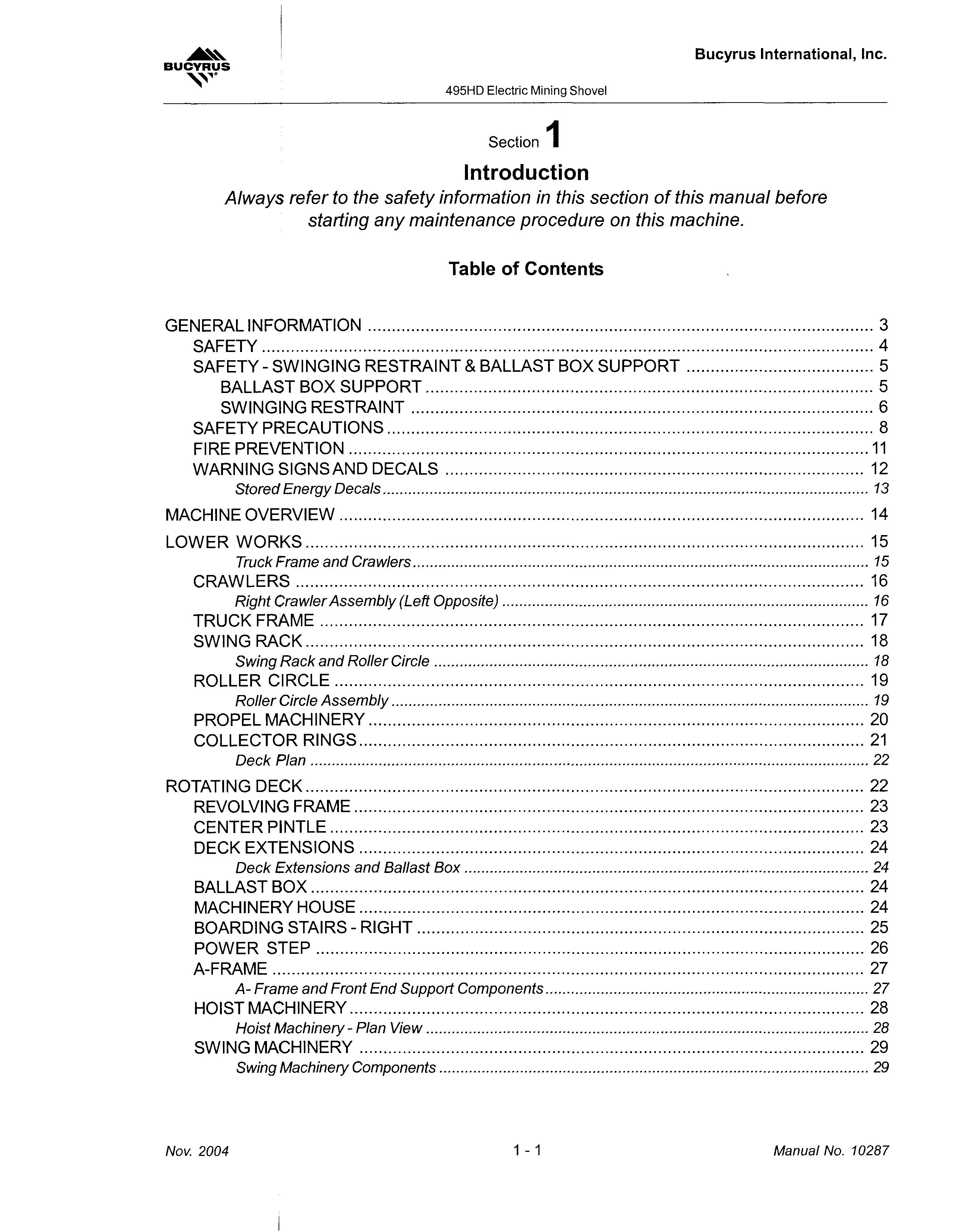
Table of Contents GENERAL INFORMATION 3 SAFETY 4 SAFETY - SWINGING RESTRAINT & BALLAST BOX SUPPORT 5 BALLAST BOX SUPPORT 5 SWINGING RESTRAINT 6 SAFETY PRECAUTIONS 8 FIRE PREVENTION 11 WARNING SIGNS AND DECALS 12 Stored Energy Decals 13 MACHINE OVERVIEW 14 LOWER WORKS 15 Truck Frame and Crawlers 15 CRAWLERS 16 Right Crawler Assembly (Left Opposite) 16 TRUCK FRAME 17 SWING RACK 18 Swing Rack and Roller Circle 18 ROLLER CI RCLE 19 Roller Circle Assembly 19 PROPEL MACHINERY 20 COLLECTOR RINGS 21 Deck Plan 22 ROTATING DECK 22 REVOLVING FRAME 23 CENTER PiNTLE 23 DECK EXTENSIONS 24 Deck Extensions and Ballast Box 24 BALLAST BOX 24 MACHINERY HOUSE 24 BOARDING STAIRS - RIGHT 25 POWER STEP 26 A-FRAME 27 A- Frame and Front End Support Components 27 HOIST MACHINERy 28 Hoist Machinery - Plan View 28 SWING MACHINERY 29 Swing Machinery Components 29 Nov. 2004 1-1 Manual No. 10287 BI005584
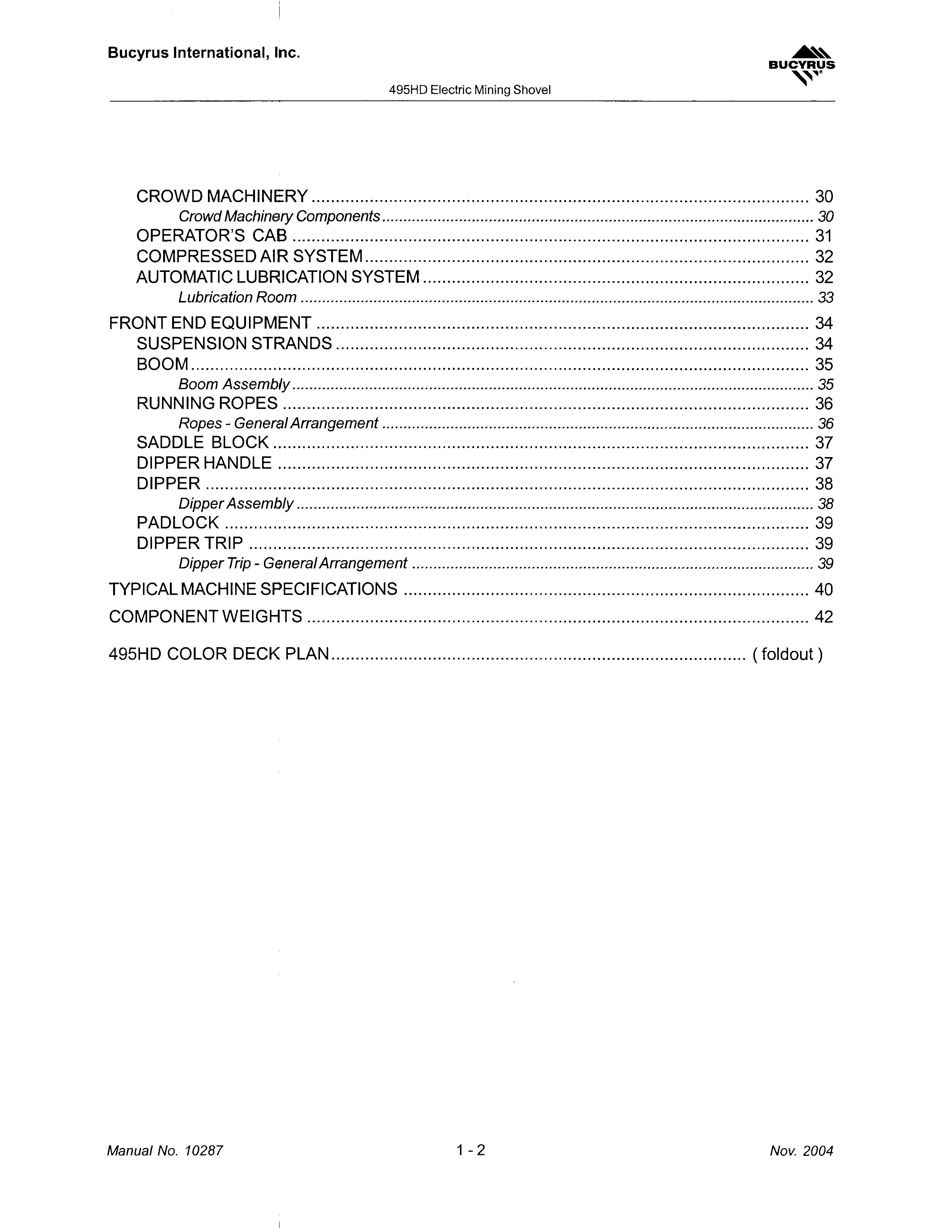
Bucyrus International, Inc. 495HD Electric Mining Shovel BUCYRUS CROWD MACHINERY 30 Crowd Machinery Components 30 OPERATOR'S CAB 31 COMPRESSED AIR SYSTEM 32 AUTOMATIC LUBRICATION SYSTEM 32 Lubrication Room 33 FRONT END EQUIPMENT 34 SUSPENSION STRANDS 34 BOOM 35 Boom Assembly 35 RUNNING ROPES 36 Ropes - General Arrangement 36 SADDLE BLOCK 37 DIPPER HANDLE 37 DIPPER 38 Dipper Assembly 38 PADLOCK 39 DIPPER TRIP 39 Dipper Trip - General Arrangement 39 TYPICAL MACHINE SPECIFICATIONS 40 COMPONENT WEIGHTS 42 495HD COLOR DECK PLAN (foldout) Manual No. 10287 1-2 Nov. 2004 BI005584
GENERAL INFORMATION
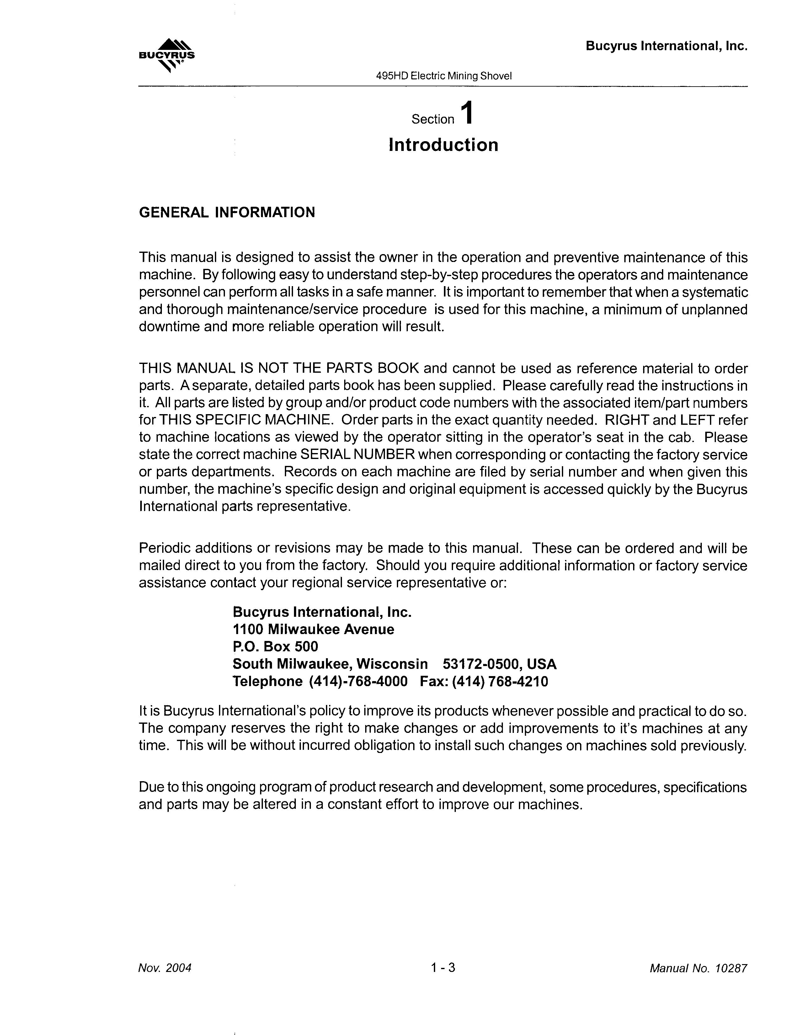
This manual is designed to assist the owner in the operation and preventive maintenance of this machine. By following easy to understand step-by-step procedures the operators and maintenance personnel can perform all tasks in a safe manner. It is important to remember that when a systematic and thorough maintenance/service procedure is used for this machine, a minimum of unplanned downtime and more reliable operation will result.
THIS MANUAL IS NOT THE PARTS BOOK and cannot be used as reference material to order parts. A separate,detailed parts book has been supplied. Please carefully read the instructions in it. All parts are listed by group and/or product code numbers with the associated item/part numbers forTHIS SPECIFIC MACHINE. Order parts in the exact quantity needed. RIGHT and LEFT refer to machine locations as viewed by the operator sitting in the operator's seat in the cab. Please state the correct machine SERIAL NUMBER when corresponding or contacting the factory service or parts departments. Records on each machine are filed by serial number and when given this number, the machine's specific design and original equipment is accessed quickly by the Bucyrus International parts representative.
Periodic additions or revisions may be made to this manual. These can be ordered and will be mailed direct to you from the factory. Should you require additional information or factory service assistance contact your regional service representative or:
Bucyrus International, Inc.
1100 Milwaukee Avenue
P.O. Box 500
South Milwaukee, Wisconsin 53172-0500, USA
Telephone (414)-768-4000 Fax: (414) 768-4210
It is Bucyrus International's policy to improve its products whenever possible and practical to do so. The company reserves the right to make changes or add improvements to it's machines at any time. This will be without incurred obligation to install such changes on machines sold previously.
Due to this ongoing program of product research and development, some procedures, specifications and parts may be altered in a constant effort to improve our machines.
BUCYRUS
495HD Electric Mining Shovel
Bucyrus International, Inc.
Section 1 Introduction
Nov. 2004 1-3 Manual No. 10287 BI005584
The safety alertsymbols displayed here and throughout this manual, are used to call attention to instructions concerning personal safety. Carefully read and follow these instructions and observe all SAFETY, DANGER and CAUTION graphics mounted on various areas of the machine.

Be certain anyone servicing this machine is aware of these SAFETY SYMBOLS and their definitions. If it is impossible to safely perform any of the enclosed maintenance and operational procedures, contact your regional Bucyrus service representative or the factory.
The following defines distinctions between safety instructions. In all these definitions the safety alert signal is used.
NOTE: This signal word denotes an item of required information pertaining to the equipment. A loss of time, assets, or minor injury may result if the appropriate action is not taken.
ACAUTION: AOANGER: AOANGER:
This signal word serves as a reminder of safety practices, or directs attention to specific safety practices which could prevent possible injury if precautions are not adhered to.
This signal word denotes an imminently dangerous hazard which will result in death, serious bodily injury, or serious damage to equipment if not acknowledged and appropriate action taken.
This signal word denotes an imminently dangerous electrical hazard which will result in death, serious bodily injury, or serious damage to equipment if not acknowledged and appropriate action taken.
Operating, maintaining or servicing this machine is dangerous unless performed properly. Each person must satisfy himself and his employer that he is alert, has the necessary skills, knowledge, proper tools and equipment for the task at hand. It is critical that all the methods used are safe and correct. Factory service representatives and specialists are available to provide additional information or technical assistance. The operator must be alert, physically fit and free from the influence of alcohol, drugs, or any medications that might impair his eyesight, hearing or reactions.
ACAUTION:
STORED ENERGY! Components on machine are heavy and removal of pins without proper preparation and precaution can cause serious bodily injury and/ordamage to the front-end of the machine.
Safety must always be paramount!
Consult your supervisor when safety is in doubt.
Bucyrus International, Inc. SAFETY 495HD Electric Mining Shovel BUCYRUS
Manual No. 10287 1-4 Nov. 2004 BI005584
SAFETY - SWINGING RESTRAINT & BALLAST BOX SUPPORT
BALLAST BOX SUPPORT
Before performing any maintenance on the mining shovel, it should be resting on a firm, level surface.
Any mining shovel field work that requires the removal or lowering of the boom must incorporate additional support of the ballast box. The supports may be wooden cribbing or steel structures. Two supports positioned side-by-side on level ground are recommended. These supports are intended to accept vertical loads only. To prevent machine rotation use the swing brakes, cable stays, welded ties, etc. Refer to "SWING RESTRAINT" below.

When electric-powered, cable-style mining shovels are properly ballasted and operational, the center of gravity for the machine's upper works lies within the roller circle area. This assumes that the boom is attached to the machine and in its elevated, working position. As such, the machine should not be prone to tipping.
Boom removal or lowering will cause the center of gravity to shift toward the ballast box, decreasing machine stability. Stability is further dependent on the orientation of the upper works relative to the undercarriage. The machine may tip more easily over one of the four quadrants of the crawler mounting than it may over others.
Normally the machine is more likely to tip over the rear-most lower-roller than over the side of a crawler. Therefore, with the boom removed and the ballast box sitting over the rear of the crawlers, the machine may be unstable. Because ballast quantities differ from machine to machine and model to model, it is recommended that the ballast box be supported before beginning any procedure to lower and/or remove the boom.
BUCYRUS 495HD Electric Mining Shovel Bucyrus International, Inc.
Ballast Box
Firm, Level Ground Nov. 2004 1-5 Manual No. 10287 BI005584
Cribbing or Steel Support Structure (1 on each side of Ballast Box)
SWINGING RESTRAINT
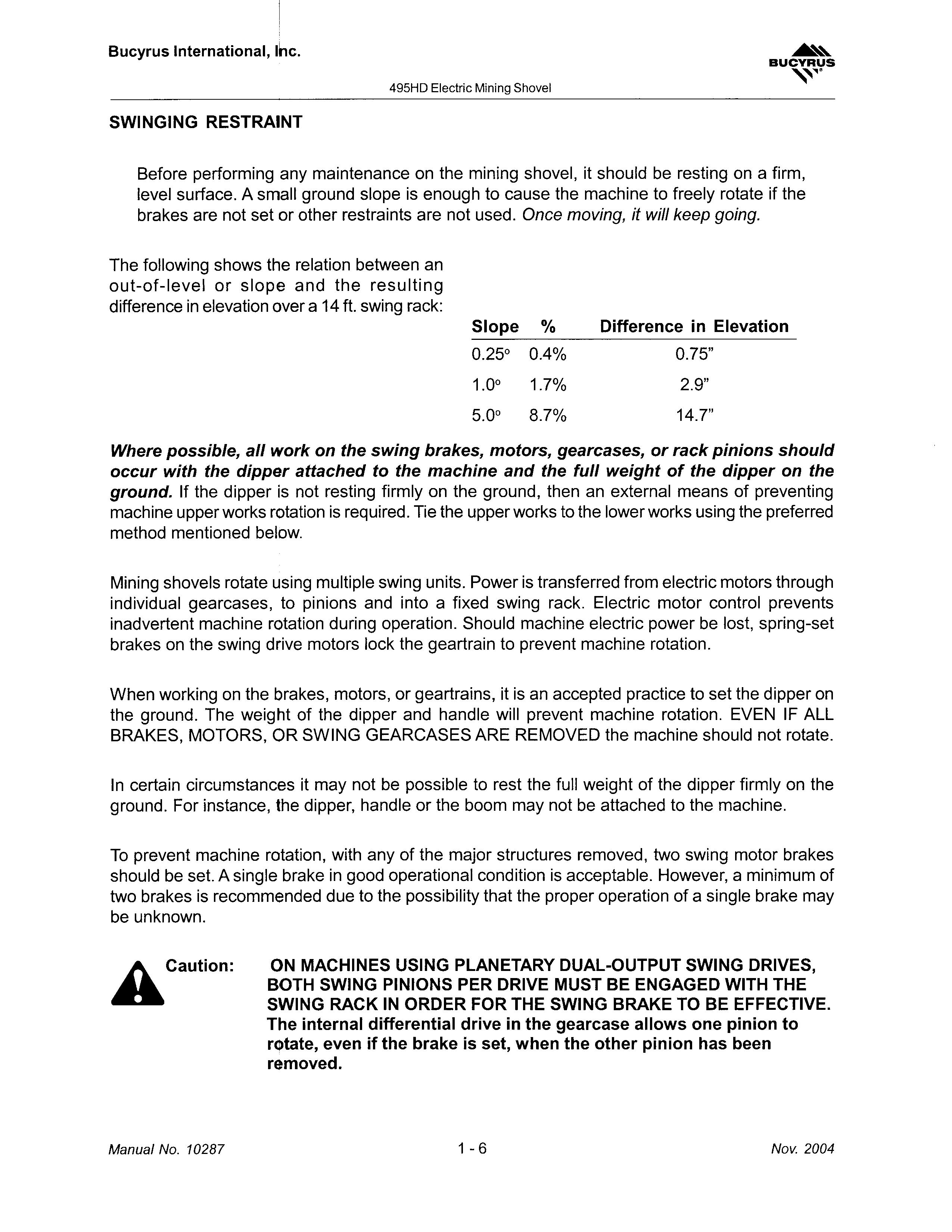
Before performing any maintenance on themining shovel, it should be resting on a firm, level surface. A small ground slope is enough to cause the machine to freely rotate if the brakes are not set or other restraints are not used. Once moving, it will keep going.
The following shows the relation between an out-of-Ievel or slope and the resulting difference in elevation over a 14 ft. swing rack:
Where possible, all work on the swing brakes, motors, gearcases, or rack pinions should occur with the dipper attached to the machine and the full weight of the dipper on the ground. If the dipper is not resting firmly on the ground, then an external means of preventing machine upper works rotation is required. Tie the upper works to the lower works using the preferred method mentioned below.
Mining shovels rotate using multiple swing units. Power is transferred from electric motors through individual gearcases, to pinions and into a fixed swing rack. Electric motor control prevents inadvertent machine rotation during operation. Should machine electric power be lost, spring-set brakes on the swing drive motors lock the geartrain to prevent machine rotation.
When working on the brakes, motors, or geartrains, it is an accepted practice to set the dipper on the ground. The weight of the dipper and handle will prevent machine rotation. EVEN IF ALL BRAKES, MOTORS, OR SWING GEARCASES ARE REMOVED the machine should not rotate.
In certain circumstances it may not be possible to rest the full weight of the dipper firmly on the ground. For instance, the dipper, handle or the boom may not be attached to the machine.
To prevent machine rotation, with any of the major structures removed, two swing motor brakes should be set. A single brake in good operational condition is acceptable. However, a minimum of two brakes is recommended due to the possibility that the proper operation of a single brake may be unknown.
ACaution: ON MACHINES USING PLANETARY DUAL-OUTPUT SWING DRIVES, BOTH SWING PINIONS PER DRIVE MUST BE ENGAGED WITH THE SWING RACK IN ORDER FOR THE SWING BRAKE TO BE EFFECTIVE. The internal differential drive in the gearcase allows one pinion to rotate, even if the brake is set, when the other pinion has been removed.
Bucyrus International, Inc.
BUCYRUS '\, '
495HD Electric Mining Shovel
Slope % 0.25° 0.4% 1.0° 1.7% 5.0° 8.7% Difference in Elevation 0.75" 2.9" 14.7"
Manual No. 10287 1-6 Nov. 2004 BI005584
An external means of preventing machine rotation must be used - if the dipper is not resting firmly on the ground and if any of the following are true:
• Two brakes are not effectively set and coupled to the motors, or The motors and geartrain are not fully coupled to the swing pinions, or The swing pinions are not engaged to the swing rack

The preferred method to prevent machine rotation is to use a pair of one inch diameter steel cables to tie the upper works to the lower works. Other alternatives such as welded plates etc. can also be used.
To use the steel cables, attach one end of each cable to the bottom surface of the revolving frame. Attach the other end of each cable to thetop surface of the truck frame. This arrangement will prevent relative motion between the revolving frame and the truck frame. Installation of these cable restraints should become a part of the lockout procedure if conditions so warrant.
For typical part numbers and locating dimensions, refer to Bucyrus drawing E021447
BUCYRUS 495HD
Bucyrus International, Inc.
Electric Mining Shovel
svvgrstnt
Revolving Frame Truck Frame (Front View)
./l1
Front of Crawlers
Rotation
Front of Revolving Frame
Nov. 2004 1-7 Manual No. 10287 BI005584
SAFETY PRECAUTIONS
General Precautions:
• The employment of qualified maintenance personnel, through a scheduled maintenance program, is the best way to minimize machine downtime and maximize productivity of equipment.
• Keep hands, feet and clothing away from rotating parts.
• Wear a hard hat, safety shoes and protective lenses at all times.
• Replace any and all safety and warning placards if they are defaced or removed from the machine.
• Think before you act. Carelessness is one luxury the service man cannot afford.
• Excessive or repeated skin contact with sealants or solvents may cause skin irritation. In case of skin contact refer to the Material Safety Data Sheet (MSDS) for that material and the suggested method of cleanup.
• Inspect safety catches (keepers) on all hoist hooks. Do not take a chance, the load could slip off of the hook if they are not functioning properly.
• If a heavy item begins to fall, let it fall, don't try to catch it.
• Keep yourwork area organized and clean. Wipe up oil or spills of any kind immediately. Keep tools and parts off of the ground. Eliminate the possibility of a fall, slipping or tripping.
• Floors, walkways and stairways must be clean and dry. After fluid draining operations be sure all spillage is cleaned up.
• Electrical cords and wet metal floors make a dangerous combination.
• Regularly inspect for any loose bolts or locking devices and properly secure them.
• Use extreme caution while working near any electrical lines or equipment whether it be high or low voltage. Never attempt electrical repairs unless you are qualified.
• Check limit switches for proper operation.
• After servicing, be sure all tools, parts or servicing equipment are removed from the machine and secured in an appropriate storage area.
• Mechanical Brakes are designed for use as static holding brakes only. Use as a motion (dynamic) brake in emergency situations only.
• Use proper interior and exterior lighting.
• Install and maintain proper grounding and ground fault protection systems.
• Allow electrical and maintenance to be performed only by a qualified electrician.
• Use extreme caution when working around drilled holes.
Bucyrus International, Inc.
495HD Electric Mining Shovel BUCYRUS
Manual No. 10287 1-8 Nov. 2004 BI005584
Maintenance Precautions:

• Do not wear rings, wristwatches or loose fitting clothing when working on machinery. They could get caught on moving parts causing serious injury.
• Always wear a safety belt or harness when the danger of falling exists.
• Always have a second person to monitor the lifeline when working in confined spaces.
• Do not start an engine indoors unless adequate exhaust ventilators are provided and in operation.
• Never utilize the machine air or hydraulic systems for support when working on the machine. Deactivate or isolate the entire system prior to performing maintenance.
• Equipment should be parked on level ground at all times during machine servicing and periods of idleness.
• Cranes and hoists must be of sufficient capacity to lift the heavier components (gearcases, pipe arms, etc.) Always work within the limitations of the equipment being utilized.
• Be sure heavy items are properly rigged and supported from cranes or hoists before removing supporting members from the machine.
• Utilize guide lines or ropes to minimize the swing of suspended heavy components.
• Have sufficient service personnel available when removing or installing large heavy items to maintain control at all times.
• Always use safety stands in conjunction with hydraulic jacks or hoists. Do not rely on the jack or hoist to carry the load, they could fail.
• When disassembling a machine, be sure to use safety stands and adequate cribbing to prevent tipping or rollover of components.
• When using an oxy/acetylene torch, always wearwelding goggles and gloves.Keep a charged fire extinguisher within reach. Be sure the acetylene and oxygen tanks are separated by a metal shield and are chained to the cart.
• Use pullers to remove bearings, bushings, gears, cylinder sleeves, etc. when applicable. Use hammers, punches and chisels only when absolutely necessary. Always be sure to wear safety glasses.
• Use extreme caution when using compressed air to dry parts. Use approved air blowguns, do not exceed 30 PSI (207 kPa), wear safety glasses or goggles and use proper shielding to protect everyone in the work area.
• Be sure to promptly reinstall safety devices, guards or shields after adjusting and/or servicing the machine.
• Protective eye goggles should be worn at all times when working on the air conditioning system. Work on the air conditioning system only in a well ventilated area.
BUCYRUS 495HD Electric Mining Shovel Bucyrus International, Inc.
Nov. 2004 1-9 Manual No. 10287 BI005584
• Wipe away excess lubricants around bearings and gears. Never lubricate parts in motion.
• Always wear approved rubber gloves and use insulated hooks or tongs when handling trail cable.
Operating Precautions:
• Wear hearing protection when exposed to the following noise levels in excess of the period indicated:
8 hours at 90 dBa
4 hours at 95 dBa
2 hours at 100 dBa
1 hour at 105 dBa
30 minutes at 110 dBa
15 minutes at 115 dBa
• When in doubt about the noise level, wear approved hearing protection.
• Do not attempt to get on or off the machine while it is in operation. Notify the operator prior to any attempt to board/exit the machine.
• Do not move or operate the machine without first knowing the location and purpose of all personnel, test or support equipment, on or near the machine.
• Do not allow unauthorized personnel on board the machine while in operation.
• Use audible signals to warn of machine movements. A signal horn button is provided for this purpose.
• Do not propel until the travel route has been cleared of obstructions.
• Do not propel the machine on a slope greater than that specified in SLOPE LIMITATIONS in Section 2- OPERATION.
• Prevent trail cable from being dragged on the ground for long distances or at high speeds.
• Limit the amount of cable being pulled by the machine. Pulling too much cable will damage both the cable and the machine.
Bucyrus International, Inc.
BUCYRUS
495HD Electric Mining Shovel
Manual No. 10287 1- 10 Nov. 2004 BI005584
FIRE PREVENTION
Always have a "charged" fire extinguisher on hand and know how to use it. Inspect and service the extinguisher as indicated on its instruction plate. DO NOT smoke while handling flammables or when near batteries.
Inspect all lines, tubes and hoses carefully. Tighten all connections to the recommended torque. See Chapter 4 of this manual for the Scheduled Maintenance recommendations and the Daily Inspection procedure.

Repair or replace loose or damaged lines, tubes and hoses as soon as possible.
Make certain all clamps, guards and shields are replaced correctly so as to prevent vibration and the chafing of parts during operation.
• DO NOT carry flammable fluids such as gasoline or solvents on board the machine.
DO NOT over-bend or strike pressurized lines or hoses. DO NOT install bent or damaged lines, tubes, or hoses. Replace them immediately.
DO NOT start the machine or move any of the controls if a warning tag is attached to the controls or the start panel.
Fire Extinguisher Locations
Keep all cleaning rags properly stored. DO NOT discard them into a pile on board.
• Keep all structural frame compartments, walkways and work areas clean and free of lubricant residue.
NEVER weld, burn, or perform service on the machine alone. If a motor or other component is running hot, shutdown the machine until it has cooled and the cause is determined and repaired.
BUCYRUS ''''\' 495HD Electric Mining Shovel Bucyrus International, Inc.
• Fire = Extinguisher Location I I I I : fQl: I I L_.L.---'----_-+ .L-..J.. i Front of Machine
Nov. 2004 1- 11 Manual No. 10287 BI005584
WARNING SIGNS AND DECALS
The placards depicted below are mounted on the machine as delivered from Bucyrus International, Inc. These hazard warning placards convey information to operators, maintenance personnel, or anyone who will be on or near the machine. The information is designed to help prevent situations which may result in injury to personnel or damage to the machine.
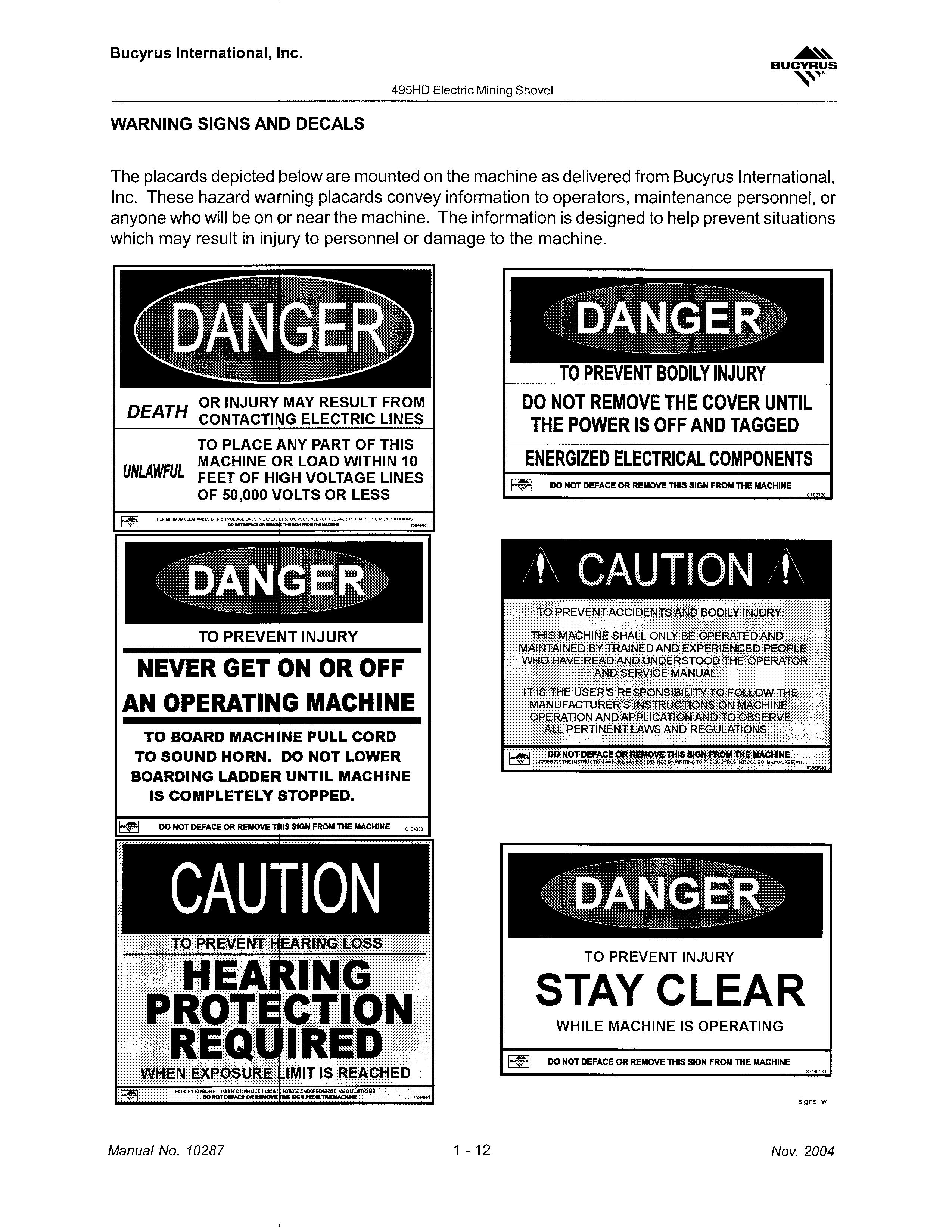
TO PREVENT BODILY INJURY
OR INJURY MAY RESULT FROM DEATH CONTACTING ELECTRIC LINES TO PLACE ANY PART OF THIS MACHINE OR LOAD WITHIN 10 UNLAWFUL FEET OF HIGH VOLTAGE LINES OF 50,000 VOLTS OR LESS
DO NOT REMOVE THE COVER UNTIL THE POWER IS OFF AND TAGGED ENERGIZED ELECTRICAL COMPONENTS
TO PREVENT INJURY
NEVER GET ON OR OFF AN OPERATING MACHINE
TO BOARD MACHINE PULL CORD TO SOUND HORN. DO NOT LOWER BOARDING LADDER UNTIL MACHINE IS COMPLETELY STOPPED.
Bucyrus International, Inc.
495HD Electric Mining Shovel BUCYRUS
rn DO NOT DEFACE OR REMOVE 11IIS SIGN FROM TIE MACHINE Manual No. 10287 1- 12
DO NOT DEFACE OR REMOVE 11115 SIGN FROM THE MACHINE -, '" ,,:illlIIlulB., " •7
PREVENT INJURY STIIY CLEIIR WHILE MACHINE IS OPERATING DO NOT DEFACE OR REMOVE THS SIGN FROM THE MACHINE Nov. 2004 BI005584
TO

BUCYRUS ""l' Bucyrus International, Inc. 495HD Electric Mining Shovel BUCYRUS· 00 !NOT DEFACE OR REMOVE THlS S1.GN FRON THE MACHINE TO PREVENT INJURY OR DEATH PROPERLY SUPPORT SHAFT 11 BEFORE REMOVING RETAINER PLATE Q REFER TO MAINTENANCE MANUAL FOR PROCEOURES 1'" sed 1148 Stored Energy Decals Nov. 2004 1- 13 Manual No. 10287 BI005584
495HD Electric Mining Shovel
MACHINE OVERVIEW
This Mining Shovel is designed and constructed to provide efficient service under the most severe conditions. The machine is built to the highest possible standards and will provide trouble free operation if properly maintained. This section of the manual introduces the machine and its functional capabilities and limitations.

Bucyrus International, tnc.
BUCYRUS
Manual No. 10287
Machinery House
1- 14
Hydraulic Unit, Crowd Rope Adjusting
Nov. 2004 BI005584
141157nm
LOWER WORKS
The lower works is comprised of the truck frame, right and left crawler frames, crawler belts, propel machinery, swing rack and roller circle.

BUCYRUS '\"'1"
Bucyrus International, Inc.
495HD Electric Mining Shovel
Lw1<s1149
Propel Gearcase, Right ,/ Crawler Drive Tumbler
Center Pintle / Front of Machine
Truck Frame
Nov. 2004
Crawler Belt
1- 15 Manual No. 10287 BI005584
Truck Frame and Crawlers
495HD Electric Mining Shovel
CRAWLERS
This machine is provided with a crawler system composed of 2 independently-driven crawler frame assemblies, one on each side of the truck frame. Each crawler has its own belt driven by a sprockettype drive tumbler. Individual crawler links are heavy alloy steel castings connected by heat treated pins.
Innovative drive tumblers made from large diameter steel castings have lugs extending beyond the tumbler rims. They are mounted on forged alloy steel shafts which turn on large anti-friction bearings mountedwithin the crawler frame. The sprocket type lugs provide a large area of contact against the crawler links, extending the life of both links and tumblers.

Lower rollers rotate on forged steel shafts mounted within the crawler side frames. Eight smaller rollers and 1 large roller per frame are specially suited to withstand the periodic single point ground reaction caused by uneven pit floors. Slide bars on top of each framesupport the upper crawler belt, reducing propel friction and drag. These side frames are stress relieved weldments comprised of steel castings and cold weather steel plates.
The crawler assemblies are bolted to the truck frame with large diameter rods and torque nuts. Each crawler belt can be independantly adjusted for tension.
cr3d1136
Thrust washer
Gearcase and Motor Support
IRear Idler Roller
Right Crawler Assembly (Left Opposite)
Bucyrus International, Inc.
BUCYRUS
Thrust
Drive
Manual No. 10287 1- 16 Nov. 2004 BI005584
Tumbler
TRUCK FRAME
The truck frame is a stress relieved welded cellular box structure which utilizes impact resistant steel in the load carrying members. The low temperature toughness of the steel assures adequate strength and durability across a wide range of temperatures frequently encountered in machine applications. A fabricated support structure welded integrally into the truck frame supports the center pintle hub area.
The inner diameter of the hub is machined to accept the center pintle bushing. Truck frame surfaces which mate to crawler side frames and swing rack are shop machined to assure proper alignment and solid foundation.

BUCYRUS '''-'''
Bucyrus International, Inc.
495HD Electric Mining Shovel
Nov. 2004 1- 17 Manual No. 10287 BI005584
/ Front of Machine
495HD Electric Mining Shovel
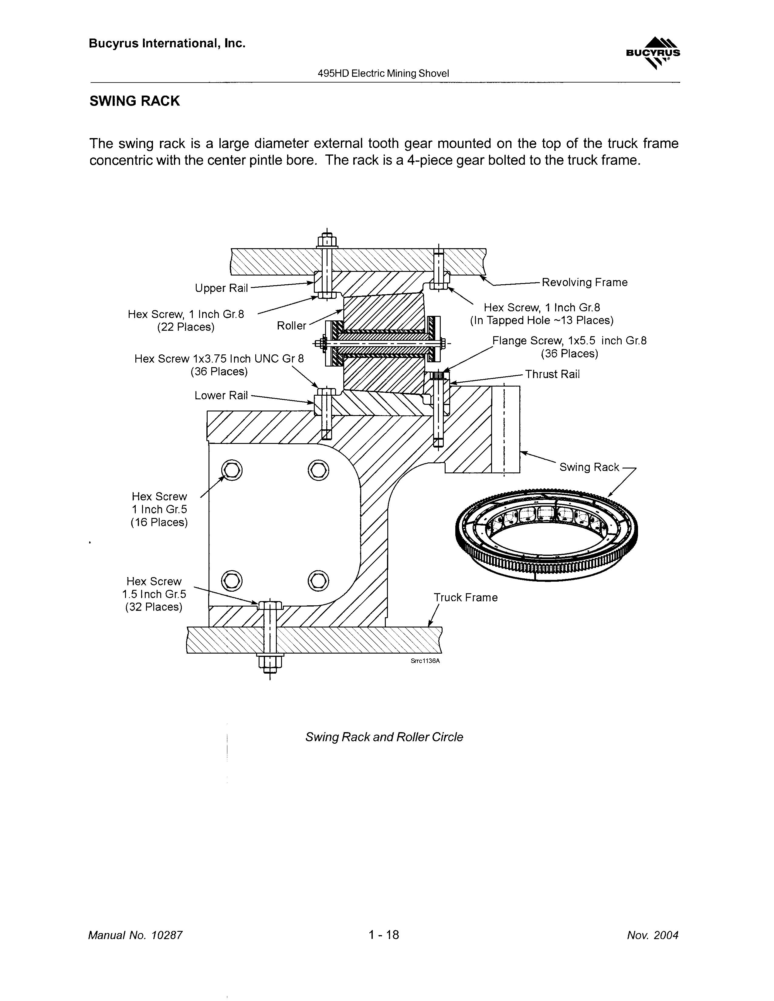
SWING RACK
The swing rack is a large diameter external tooth gear mounted on thetop of the truck frame concentric with the center pintle bore. The rack is a 4-piece gear bolted to the truck frame.
'----- Revolving Frame
Hex Screw, 1 Inch Gr.8 (22 Places)
Hex Screw 1x3.75 Inch UNC Gr 8 (36 Places)
Hex Screw 1 Inch Gr.5 (16 Places) Hex Screw 1.5lnch Gr.5 (32 Places)
Swing Rack and Roller Circle
Hex Screw, 1 Inch Gr.8 (In Tapped Hole -13 Places)
Flange Screw, 1x5.5 inch Gr.8 (36 Places)
Thrust Rail
Bucyrus International, Inc.
BUCYRUS '\,,,.
Manual No. 10287 1- 18 Nov. 2004 BI005584
495HD Electric Mining Shovel
ROLLER CIRCLE
The roller circle is composed of the upper rails, lower rails, thrust rails, 50 tapered rollers and inner/ outer roller cages. The lower rail segments are secured to the top surface of the swing rack forming a continuous rolling path for the rollers. The upper rails are attached to the bottom of the revolving frame, fore and aft of the center pintle. Upper rail ends are tapered to provide a smooth approach for the rollers. Rollers are tapered to ensure non-skid contact with rails. The rollers are spaced and aligned with pins and low maintenance polyurethane bushings.
Nov. 2004
In ner Retainer Plate
Nut, Self-Locki ng------·.
Keeper Plate
Flat Washer
.' 1"
Flat Washer I
Outer Retainer Plate
Roller Circle Assembly

1- 19
Capscrew, Hex .62 Inch Gr.8 -2 per Roller
Manual No. 10287
BUCYRUS '-,
Bucyrus International, Inc.
BI005584
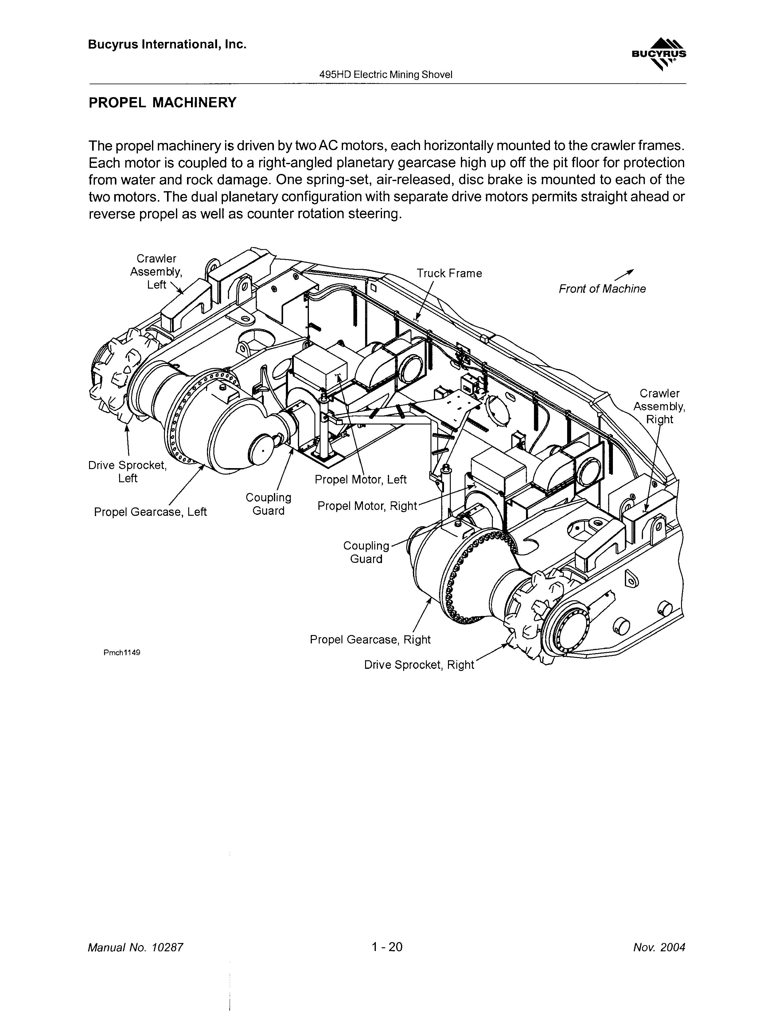
PROPEL MACHINERY
The propel machinery is driven by two AC motors, each horizontally mounted to the crawler frames. Each motor is coupled to a right-angled planetary gearcase high up off the pit floor for protection from water and rock damage. One spring-set, air-released, disc brake is mounted to each of the two motors. The dual planetary configuration with separate drive motors permits straight ahead or reverse propel as well as counter rotation steering.
Bucyrus International, Inc.
BUCYRUS ....
495HD Electric Mining Shovel
Propel Gearcase, Left
Coupling Guard
Pmch1149
Drive Sprocket, Right Manual No. 10287 1- 20 Nov. 2004
./ Front of Machine BI005584
495HD Electric Mining Shovel
COLLECTOR RINGS
High voltage collector rings between the revolving frame and truck frame transfer electric power from the truck frame to the rotating deck. Electric power enters the truck frame between the propel motors and is transferred by means of collector ring shoes to the collector rings. The shoes are mounted between the cast center pintle hub and the swing rack.
Collector Ring Enclosure
Junction Box, Propel - Right Collector Rings, Propel and Low Voltage (Rear Section View)
Collector Rings, Main High Voltage

BUCYRUS
Bucyrus International, Inc.
CL Rotation
Collector Rings for Phase 1,2 and 3.
Ground Collector Ring
clrl1136
Bottom of Revolving Frame
Nov. 2004 1- 21 Manual No.
BI005584
Top of Truck Frame
10287
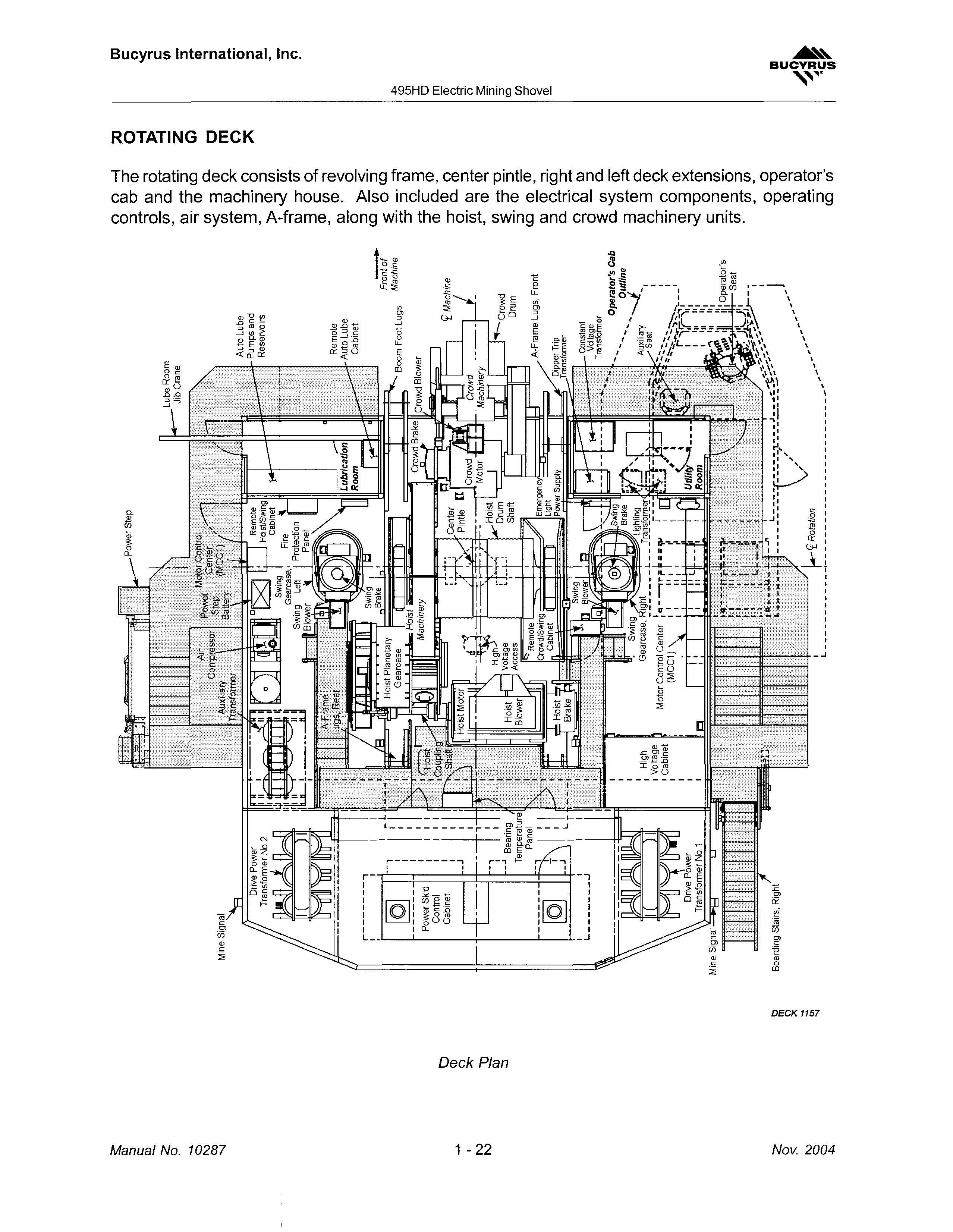
m c .... 'CpIII .j>. (jJ c.n I o m CD o· s: S' S' c.o Ol ::T ;;0 OJ c: 0 0 '< ., c: ::! til Z 5" Q .... Cll ., C :::l III m .... (') o' " :::l :::l (')(') -1 ° Ol :::T ..., Ol ..., 0:::::lS- Ol c.. Ol · ....... Ol ....... S' ". to Ol Ol (')CD(')7\ 3 2": 8 • :::::l:::::l »CDOl ..!." -< iii" ...,Ol :::T Ol 3 °° CD C• Ol (i) Ol <-°0»-:::::l :5. tOOl:::::l :E 0tO -'-' - :::::lm:::T(') ....... -3:::TCCDCD c... :::T CD (') ° c.. CD _. Ol :::::l • CD..., Ol "0 :E :::T _. S'CD to CD .CD Ol CD :::::I.:::::l(')tOc..!:f:::T(') ('). 0;e Ol :::::l :E Ol c.. c.. '< CD OlCDc..(') 3 CD 2":(')R- :::::l ° CD CD 3 -<"0 CD C ° :::::l :::::l :::::lCD ;::;: ° Ol :::::l:::::l • pi.Ol °° "0"0 CD CD mm :::::l ..., to Ol- Front of Machine Constant VdtageTransfonner Operator's Cab Outline Auxiliary -......t ;' Seat , : : I "W" .. I 'II II' I 'n II' .." III II' II: ,\ III Operator's ,_ "JLl"J:' , .. , ---------r-----;;'-L_________ 1-"0"'= V' J ------------------------------------------J -1 I I I I I : 4' II _J : -1 _, ,I _J [Q] Power Skid Control Cabinet r-------,I I I ,I I [Q] .J <h .... tJ CD R- ::Q OJ :J I\.) o o -l>. o I\.) 00 'I N N :J c: BI005584
REVOLVING FRAME
The revolving frame is the main structural member of the rotating deck. It is a welded, stress relieved structure with integral lugs for mounting the Aframe, crowd machinery and boom. Provisions are made for mounting deck extensions, operator's cab, ballast box and swing gearcases. Machined pads on the deck locate hoist drive motor and machinery frames.
Refer to the following page for a view of the revolving frame assembly with deck extensions and ballast box.
The revolving frame is connected to the truck frame by the center pintle.
Lock Bar, Upper (4 Places) ,.
Capscrew, Hex 1.25 Inch Gr.5
CENTER PINTLE
The center pintle is a large diameter, hollow cylindrical forging and threaded at the bottom. A bronze coated steel core spherical thrust washer between the lower adjusting nut and the bottom surface of the truck frame provides a wear surface for pintle loads. The top of the center pintle is doweled and bolted to the revolving frame using a split clamping collar.

The hollow pintle provides passage for air and grease lines and electrical cables from the revolving frame to the lower works using a swivel and collector ring assembly,.
Capscrew, Hex 1.5 Inch Gr.8
Revolving Frame
Center Pintle
Lock Bar, Lower (2 Places)
Washer, Lower Retaining Nut
BUCYRUS "'-""lO Bucyrus International, Inc.
495HD Electric Mining Shovel
Nov. 2004 1- 23 Manual No. 10287 BI005584
• Thank you very much for reading the preview of the manual.
• You can download the complete manual from: www.heydownloads.com by clicking the link below
• Please note: If there is no response to CLICKING the link, please download this PDF first and then click on it.
CLICK HERE TO DOWNLOAD THE COMPLETE MANUAL
CLICK HERE TO DOWNLOAD THE COMPLETE MANUAL