Technical Manual
• Thank you very much for reading the preview of the manual.
• You can download the complete manual from: www.heydownloads.com by clicking the link below
• Please note: If there is no response to CLICKING the link, please download this PDF first and then click on it.


49RIII Blast Hole Drill
49RIII
Blast Hole Drill
Maintenance and Operation Manual
Manual No.1 0257
sn: 141138, Lot 65
sn: 141139, Lot 67
-Table of Contents-
This manual is divided into major sections covering the various serviceable components and systems of the 49RIII Blast Hole Drill. These sections and their contents are organized as shown below.
Section 1- INTRODUCTION
Section 2- OPERATION
Section 3- LUBRICATION
Section 4- SCHEDULED MAINTENANCE
Section 5- MAJOR MAINTENANCE
Section 6- BRAKES AND COUPLINGS
Section 7- COMPRESSED AIR SYSTEM
Section 8- HEATING, VENTILATION AND AIR CONDITIONING
ADANGER:
THE MAINTENANCE
MACHINE. ELECTRICAL EQUIPMENT SERVICED BY QUALIFIED TO WORK WITH HIGH VARIABLE FREQUENCY OR WARD LOOP FAILURE COULD PERSONAL
THIS MANUAL PROVIDES INFORMATION AND DATA FOR THE MAINTENANCE AND OPERATION OF THIS MACHINE. ALL ELECTRICAL EQUIPMENT MUST BE SERVICED BY QUALIFIED INDIVIDUALS WHO HAVE BEEN PROPERLY TRAINED TO WORK WITH HIGH VOLTAGE SYSTEMS, VARIABLE FREQUENCY AC DRIVES, ANDI OR WARD LEONARD LOOP DC DRIVES. FAILURE TO COMPLY COULD RESULT IN PERSONAL INJURY OR DEATH.
AADANGER:
DANGER:
DO NOT ATTEMPT MECHANICAL OR ELECTRICAL MAINTENANCE ON THIS MACHINE WITHOUT A FULL UNDERSTANDING OF EACH COMPONENT'S OPERATION AND FUNCTION. COMPONENTS UTILIZING ELECTRICAL POWER, AIR PRESSURE, HYDRAULIC PRESSURE AND COMPRESSION OR TENSION SPRINGS FOR OPERATION MUST BE DEACTIVATED AND ISOLATED PRIOR TO DISASSEMBLY.
DO NOT ATTEMPT MAINTENANCE WITHOUT FULL EACH OPERATION COMPONENTS POWER, HYDRAULIC TENSION FOR AND
The FEEDER CABLE must contain a prOVision for a ground connection, especially whenever 2,300 volts or greater are used. At the substation, the power line must terminate (see paragraph on ground circuits) to a suitable permanent ground. At the machine, the power line must securely terminate through a bolted connection to the machine frame. This provides a constant ground for the machine and its electrical equipment. Failure to provide this adequate ground endangers employees and equipment.
FEEDER CABLE a prOVision for a whenever or power must terminate ground permanent At the the line through connection to the a machine its Failure adequate endangers employees and equipment.
THE NEED FOR A POWER LINE GROUNDING CIRCUIT ADEQUATE FOR THE MACHINE CANNOT BE OVEREMPHASIZED. Without a goodgrounding system, high voltages exist between the machine and the ground. The portable trail cable and power lines supplying electric energy to the machine must have a ground wire, ample in capacity, running parallel to the main wires over the entire distance from the transformer to the machine. A suitable grounding system must be used at the transformer. Consult your local electrical supplier for details.
ADANGER:
FOR POWER GROUNDING ADEQUATE CANNOT system, high the cable have ample in capacity, to wires entire machine. system at electrical supplier for details. TO THE OF HIGH EQUIPMENT, SAFE GROUNDING SYSTEM IS REQUIRED INCLUDES CONDUCTORS IN THE CABLE, RESISTOR, AND RELATED RELAYS A CONTINUITY CHECK
DUE TO THE INHERENT DANGERS IN THE OPERATION OF HIGH VOLTAGE ELECTRICAL EQUIPMENT, A SAFE GROUNDING SYSTEM IS REQUIRED THAT INCLUDES GROUND CONDUCTORS IN THE CABLE, A NEUTRAL GROUNDING RESISTOR, AND RELATED RELAYS AND SWITCHGEAR. A GROUND CONTINUITY CHECK SYSTEM IS ALSO RECOMMENDED. 141138Jp65
No. 10257
Manual No. 10257
2004

GENERAL INFORMATION

GENERAL
is in the maintenance of this machine. By to and can perform tasks safe manner. systematic thorough for machine, of unplanned downtime more operation
This manual is designed to assist the owner in the operation and maintenance of this machine. By following easy to understand step-by-step procedures the operators and maintenance personnel can perform all tasks in a safe manner. When a systematic and thorough maintenance/service procedure is used for this machine, a minimum of unplanned downtime and more reliable operation will result.
MANUAL IS THE BOOK, be to order A has been carefully in All are listed numbers the THIS parts in needed. LEFT refer as by the sitting the state machine SERIAL corresponding on each are by and given number, specific design and equipment Bucyrus
THIS MANUAL IS NOT THE PARTS BOOK, and cannot be used as reference material to order parts. A separate, detailed parts book has been supplied. Please carefully read the instructions in it. All parts are listed by group and/or product code numbers with the associated item/part numbers for THIS SPECIFIC MACHINE. Order parts in the exact quantity needed. RIGHT and LEFT refer to machine locations as viewed by the operator sitting in the operator's seat in the cab. Please state the correct machine SERIAL NUMBER when corresponding or contacting the factory service or parts departments. Records on each machine are filed by serial number and when given this number, your machine's specific design and original equipment is accessed quickly by the Bucyrus International parts representative.
Periodic additions or revisions may be made to this manual. These can be ordered and will be mailed directly from the factory. Should you require additional information or factory service assistance contact your regional service representative or:
Periodic additions revisions to manual. ordered the factory. require assistance representative
Bucyrus International, Inc.
1100 Milwaukee Avenue
P.O. Box 500
South Milwaukee, Wisconsin, USA
Telephone (414)-768-4000
Bucyrus Box Wisconsin, (414)-768-4000
53172-0500 policy its
53172-0500
It is Bucyrus International's policy to improve its products whenever possible and practical to do so. The company reserves the right to make changes or add improvements to its machines at any time. This will be without incurred obligations to install such changes on machines sold preViously.
The right make to any time. will incurred obligations to install on machines
program of product and some improve
Due to this ongoing program of product research and development some procedures, specifications and parts may be altered in a constant effort to improve our machines.
49RIII Blast Hole Drill
SAFETY
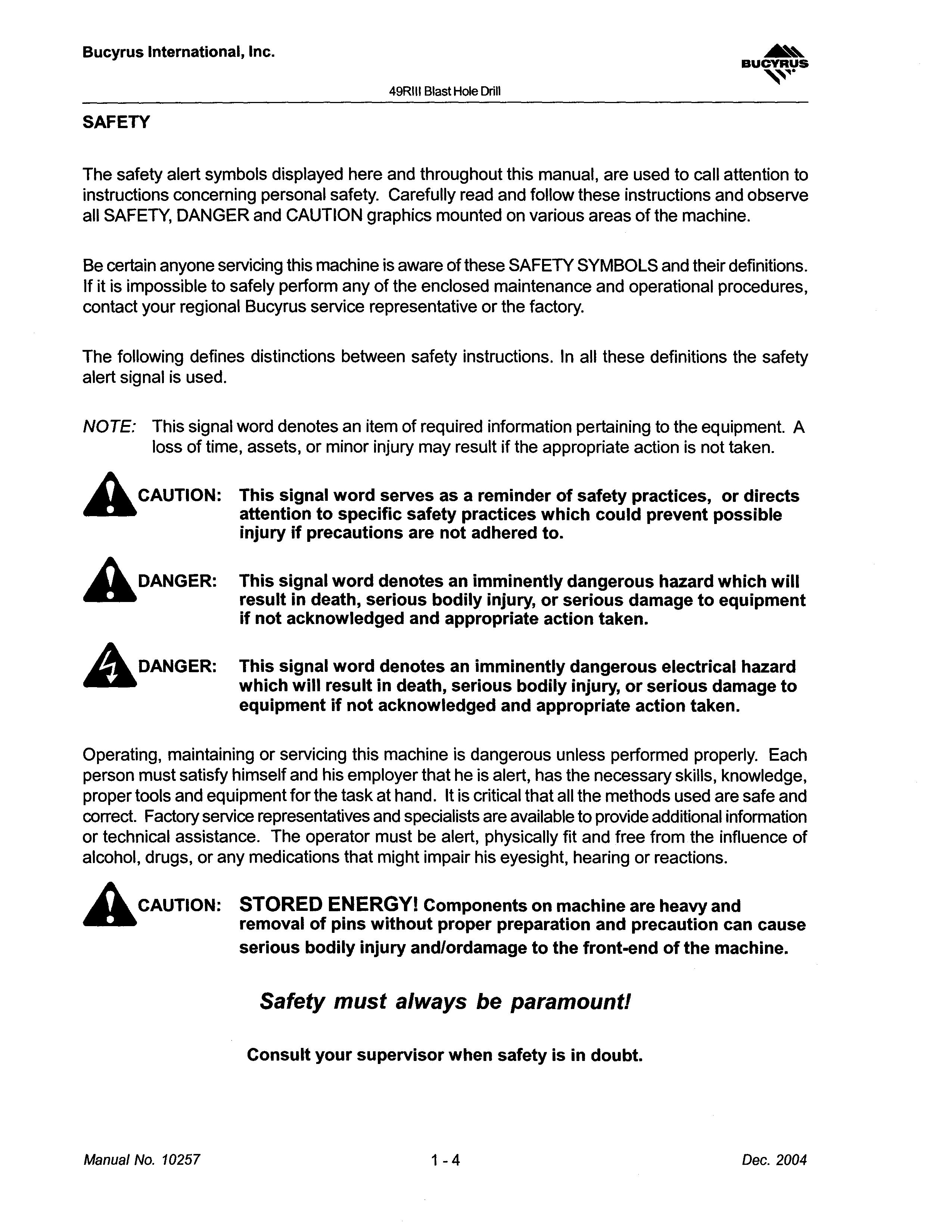
The safety alert symbols displayed here and throughout this manual, are used to call attention to instructions concerning personal safety. Carefully read and follow these instructions and observe all SAFETY, DANGER and CAUTION graphics mounted on various areas of the machine.
49RIII Drill this used call instructions concerning personal Carefully read follow these and observe all
Be certain anyone servicing this machine is aware of these SAFETY SYMBOLS and their definitions. If it is impossible to safely perform any of the enclosed maintenance and operational procedures, contact your regional Bucyrus service representative or the factory.
anyone servicing this SAFETY and If it impossible of procedures, regional Bucyrus representative or
distinctions the safety is used.
The following defines distinctions between safety instructions. In all these definitions the safety alert signal is used.
NOTE: an item required to equipment. loss time, may appropriate action not taken.
NOTE: This signal word denotes an item of required information pertaining to the equipment. A loss of time, assets, or minor injury may result if the appropriate action is not taken.
CAUTION: word reminder directs specific practices could injury adhered
A CAUTION: This signal word serves as a reminder of safety practices, or directs attention to specific safety practices which could prevent possible injury if precautions are not adhered to.
AOANGER: AOANGER:
This signal word denotes an imminently dangerous hazard which will result in death, serious bodily injury, or serious damage to equipment if not acknowledged and appropriate action taken.
This signal word denotes an imminently dangerouselectrical hazard which will result in death, serious bodily injury, or serious damage to equipment if not acknowledged and appropriate action taken.
AOANGER: signal word an dangerous which will in bodily serious if not appropriate denotes an imminently hazard which will in death, bodily or not acknowledged
Operating, maintaining or servicing this machine is dangerous unless performed properly. Each person must satisfy himself and his employer that he is alert, has the necessary skills, knowledge, proper tools and equipment for the task at hand. It is critical that all the methods used are safe and correct. Factory service representatives and specialists are available to provide additional information or technical assistance. The operator must be alert, physically fit and free from the influence of alcohol, drugs, or any medications that might impair his eyesight, hearing or reactions.
maintaining servicing this dangerous must his that is alert, knowledge, and for the critical methods Factory representatives technical must free from the influence or any his
CAUTION: STORED ENERGYI Components on machine are heavy and removal of pins without proper preparation and precaution can cause serious bodily injury and/ordamage to the front-end of the machine.
CAUTION: are heavy removal pins proper and can bodily the of the machine.
Safety must always be paramount! Consult your supervisor when safety is in doubt.
Safety paramount! supervisor is in
Maintenance Precautions:
Maintenance Precautions:

• Do not wear rings, wristwatches or loose fitting clothing when working on machinery. They could get caughton moving parts causing serious injury.
• Always wear a safety belt or harness when the danger of falling exists.
• not rings, fitting clothing working machinery. They wear a belt or harness when the of exists.
• Always have a second person to monitor the lifeline when working in confined spaces.
• Always to working
• Do not start an engine indoors unless adequate exhaust ventilators are provided and in operation.
• Never utilize the machine air or hydraulic systems for support when working on the machine. Deactivate or isolate the entire system prior to performing maintenance.
• an are in Never utilize the machine air or for when on the machine. performing Equipment should be parked level ground all times during machine servicing and periods
• Equipment should be parked on level ground at all times during machine servicing and periods of idleness.
• Cranes and hoists must be of sufficient capacity to lift the heavier components (gearcases, pipe arms, etc.) Always work within the limitations of the equipment being utilized.
• Be sure heavy items are properly rigged and supported from cranes or hoists before removing supporting members from the machine.
Cranes of sufficient lift (gearcases, within from before supporting
• Utilize guide lines or ropes to minimize the swing of suspended heavy components.
• Have sufficient service personnel available when removing or installing large heavy items to maintain control at all times.
• guide to swing heavy components. sufficient at
• Always use safety stands in conjunction with hydraulic jacks or hoists. Do not rely on the jack or hoist to carry the load, they could fail.
• When disassembling a machine, be sure to use safety stands and adequate cribbing to prevent tipping or rollover of components.
• When using an oxy/acetylene torch, always wear welding goggles and gloves.Keep a charged fire extinguisher within reach. Be sure the acetylene and oxygen tanks are separated by a metal shield and are chained to the cart.
• Use pullers to remove bearings, bushings, gears, cylinder sleeves, etc. when applicable. Use hammers, punches and chisels only when absolutely necessary. Always be sure to wear safety glasses.
• in with or on fail. safety tipping components. When an wear and a fire to cart. Use to remove etc. when Use only safety glasses.
• Use extreme caution when using compressed air to dry parts. Use approved air blowguns, do not exceed 30 PSI (207 kPa), wear safety glasses or goggles and use proper shielding to protect everyone in the work area.
Use extreme caution when air to Use air do exceed 30 glasses
everyone in area.
Be sure to reinstall or shields after and/or
• Be sure to promptly reinstall safety devices, guards or shields after adjusting and/or servicing the machine.
• Protective eye goggles should be worn at all times when working on the air conditioning system. Work on the air conditioning system only in a well ventilated area.
• Wipe away excess lubricants around bearings and gears. Never lubricate parts in motion.
• Always wear approved rubber gloves, and use insulated hooks or tongs when handling trail cable.
Manual No. 10257
• eye worn on Always approved rubber gloves, and insulated hooks when handling trail cable. Dec. 2004
1-6
Dec. 2004
Operating Precautions:
49RIII Blast Hole Drill
49RIII Drill
exposed following noise of
• Wear hearing protection when exposed to the following noise levels in excess of the period indicated:
8 hours at 90 dBa
8 hours 90 dBa
4 hours at 95 dBa
2 hours at 100 dBa
1 hour at 105 dBa
30 minutes at 110 dBa
2 hours at 100 dBa hour at 105 dBa at dBa
15 minutes at 115 dBa
15 minutes at 115 dBa
• When in doubt about the noise level, wear approved hearing protection.
• in the noise wear protection.
• Do not attempt to get on or off the machine while it is in operation. Notify the operator prior to any attempt to board/exit the machine.
Do on the machine while it is in operation. the prior any attempt to the machine.
• Do not move or operate the machine without first knowing the location and purpose of all personnel, test or support equipment, on or near the machine.
• not move or purpose of personnel, or support equipment, on the machine.
unauthorized board machine
• Do not allow unauthorized personnel on board the machine while in operation.
• Use signals to of machine movements. A signal for

• Use audible signals to warn of machine movements. A signal horn button is provided for this purpose.
• Do not propel until the travel route has been cleared of obstructions.
Do not propel until the travel route has been cleared of obstructions. propel the machine a slope than specified in stability the at this section.
• Do not propel the machine on a slope greater than specified in the stability limits shown on the STABILITY CHART at the end of this section.
• Do not leave therotary gearbox suspended in the air when leaVing the machine unattended.
Do not leave gearbox the when unattended.
• Prevent trail cable being dragged on the ground long distances at high Limitthe the cable damage
• Prevent trail cable from being dragged on the ground for long distances or at high speeds.
• Limitthe amount of cable being dragged by the machine. Pulling too much cable will damage both the cable and the machine.
49RIII Blast Hole Drill
49RIII Blast Hole Drill
FIRE PREVENTION CONSIDERATIONS
FIRE CONSIDERATIONS
Always have a "charged" fire extinguisher on hand and knowhow to use it. Inspect and service the extinguisher as indicated on its instruction plate.
on and to and the extinguisher as indicated on its instruction
DO NOT smoke while handling flammables or when near batteries. Inspect all lines, tubes, and hoses carefully. Tighten all connections to their recommended torque specification. See Section 4 of this manual for the Scheduled Maintenance recommendations and the Walk Around Inspection procedure.
Repair or replace loose or damaged lines, tubes, and hoses as soon as possible.
Make certain that all clamps, guards, and shields are replaced correctly so as to prevent vibration and the chafing of parts during operation.
NOT while or and to specification. See Section of manual for Scheduled Walk Around Inspection procedure. tubes, and hoses as certain all clamps, guards, and shields are correctly so as and chafing of parts operation.
DO NOT carry flammable fluids such as gasoline or solvents on board themachine.
DO NOT over-bend or strike pressurized lines or hoses. DO NOT install bent or damaged lines, tubes, or hoses. Replace them immediately.
DO NOT flammable fluids such as or solvents on board themachine. NOT pressurized lines or install damaged or hoses. Replace them
DO NOT start the machine or move any of the controls if a warning tag is attached to the controls or the start panel.
NOT start the machine move any the controls a warning tag is attached the controls or the start panel.
Keep all cleaning rags properly stored. DO NOT discard them into a pile on board.
Keep all cleaning properly stored. NOT discard them into pile on board.
Keep all structural frame compartments, walkways, and work areas clean and free of lubricant residue.
all structural frame compartments, walkways, areas free lubricant residue.
NEVER or perform on the machine
NEVER weld, burn, or perform service on the machine alone. Manual No. 10257
2004
• Thank you very much for reading the preview of the manual.
• You can download the complete manual from: www.heydownloads.com by clicking the link below
• Please note: If there is no response to CLICKING the link, please download this PDF first and then click on it.
STANDARD HAND SIGNALS FOR CONTROLLING CRANE OPERATIONS
STANDARD OPERATIONS
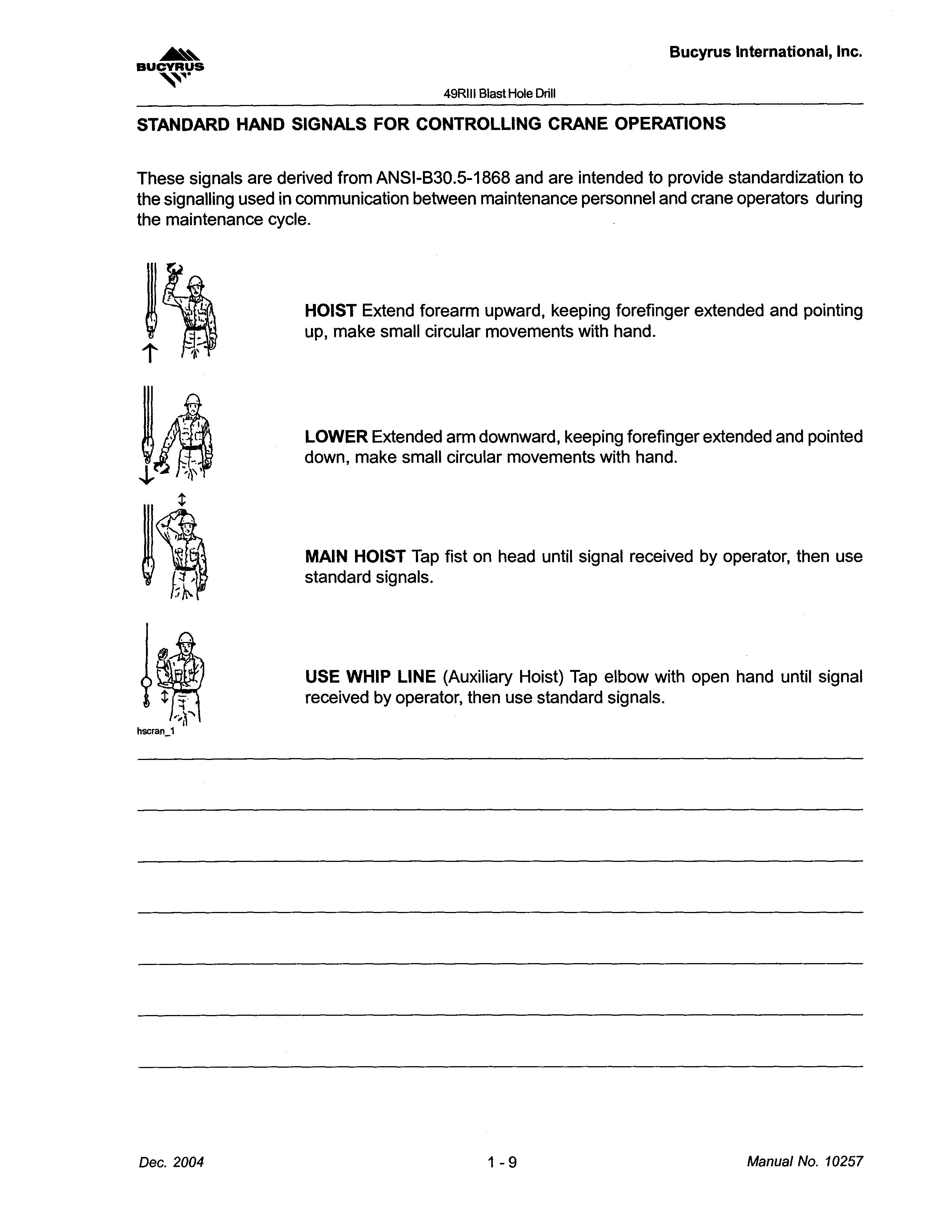
These signals are derived from ANSI-B30.5-1868 and are intended to provide standardization to the signalling used in communication between maintenance personnel and crane operators during the maintenance cycle.
HOIST Extend forearm upward, keeping forefinger extended and pointing up, make small circular movements with hand.
LOWER Extended arm downward, keeping forefinger extended and pointed down, make small circular movements with hand.
signals are derived are to standardization the signalling used communication between maintenance personnel and crane during the maintenance forearm upward, forefinger pointing make circular hand. arm downward, keeping forefinger and pointed down, make small circular movements with hand.
MAIN HOIST on signal by use standard signals.
MAIN HOIST Tap fist on head until signal received by operator, then use standard signals.
USE WHIP LINE (Auxiliary Hoist) Tap elbow signal by then use standard
USE WHIP LINE (Auxiliary Hoist) Tap elbow with open hand until signal received by operator, then use standard signals.
49RIII Blast Hole Drill
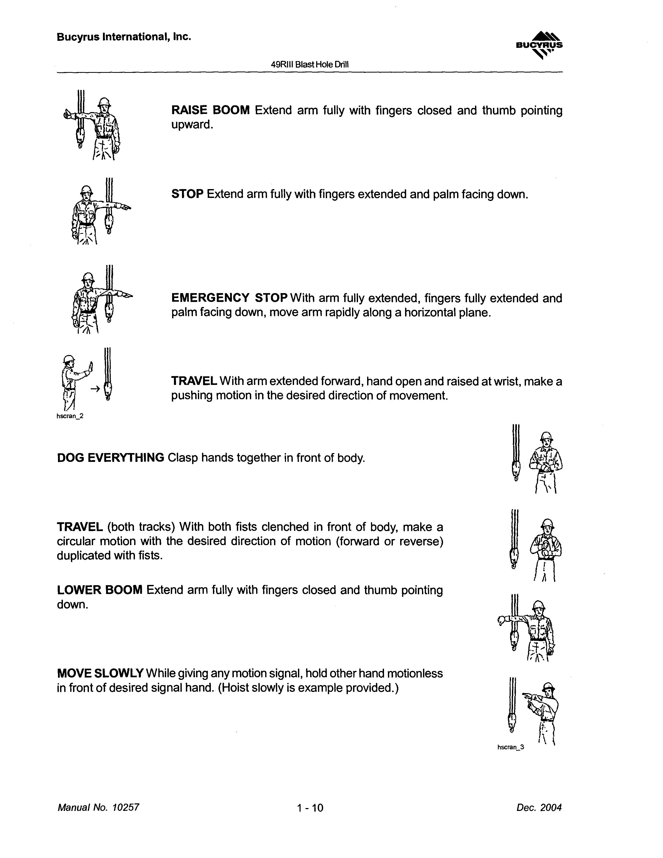
RAISE BOOM Extend arm fully with fingers closed and thumb pointing upward.
with
STOP Extend arm fully with fingers extended and palm facing down.
EMERGENCY STOP With arm fUlly extended, fingers fully extended and palm facing down, move arm rapidly along a horizontal plane.
EMERGENCY STOP With arm extended and palm down, rapidly along horizontal plane.
TRAVEL With arm extended forward, hand open and raised at wrist, make a pushing motion in the desired direction of movement.
DOG EVERYTHING Clasp hands together in front of body.
With arm extended hand and raised at make a pushing in
TRAVEL (both tracks) With both fistsclenched in front of body, make a circular motion with the desired direction of motion (forward or reverse) duplicated with fists.
LOWER BOOM Extend arm fully with fingers closed and thumb pointing down.
MOVE SLOWLY While giving any motion signal, hold other hand motionless in front of desired signal hand. (Hoist slowly is example provided.)
TRAVEL With both in body, make (forward reverse) with fists. fully fingers pointing down. giving any signal, signal (Hoist slowly provided.)
49RIII Blast Hole Drill
49RIII
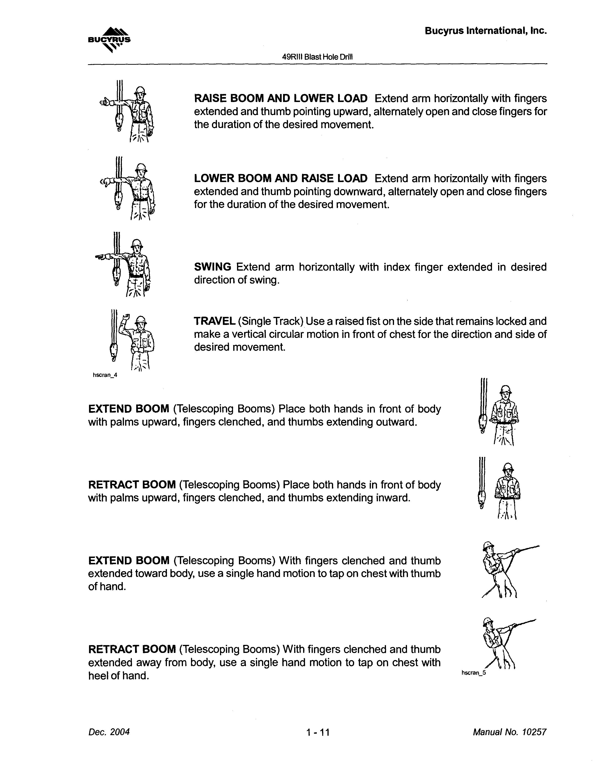
RAISE BOOM AND LOWER LOAD Extend arm horizontally with fingers extended and thumb pointing upward, alternately open and close fingers for the duration of the desired movement.
LOWER BOOM AND RAISE LOAD Extend arm horizontally with fingers extended and thumb pointing downward, alternately open and close fingers for the duration of the desired movement.
RAISE BOOM LOWER LOAD Extend fingers upward, alternately close LOWER AND fingers thumb downward, and fingers the
SWING Extend arm horizontally with index finger extended in desired direction of swing.
TRAVEL (Single Track) Use a raised fist on the side that remains locked and make a vertical circular motion in front of chest for the direction and side of desired movement.
with index of (Single Track) the and a vertical circular for direction desired
EXTEND BOOM (Telescoping Booms) Place both hands in front of body with palms upward, fingers clenched, and thumbs extending outward.
Place both hands in front upward, and
RETRACT BOOM (Telescoping Booms) Place both hands in front of body with palms upward, fingers clenched, and thumbs extending inward.
RETRACT (Telescoping hands upward, fingers and inward.
EXTEND BOOM (Telescoping Booms) With fingers clenched and thumb extended toward body, use a single hand motion to tap on chest with thumb of hand.
RETRACT BOOM (Telescoping Booms) With fingers clenched and thumb extended away from body, use a single hand motion to tap on chest with heel of hand.
EXTEND BOOM Booms) clenched use on hand. BOOM (Telescoping clenched away from use single to heel
49RIII Blast Hole Drill
WARNING SIGNS AND DECALS
The placards depicted below are mounted on the machine as delivered from Bucyrus International, Inc. These hazard warning placards convey information to operators, maintenance personnel, or anyone who will be on or near the machine. The information is designed to help prevent situations which may result in injury to personnel or damage to the machine.
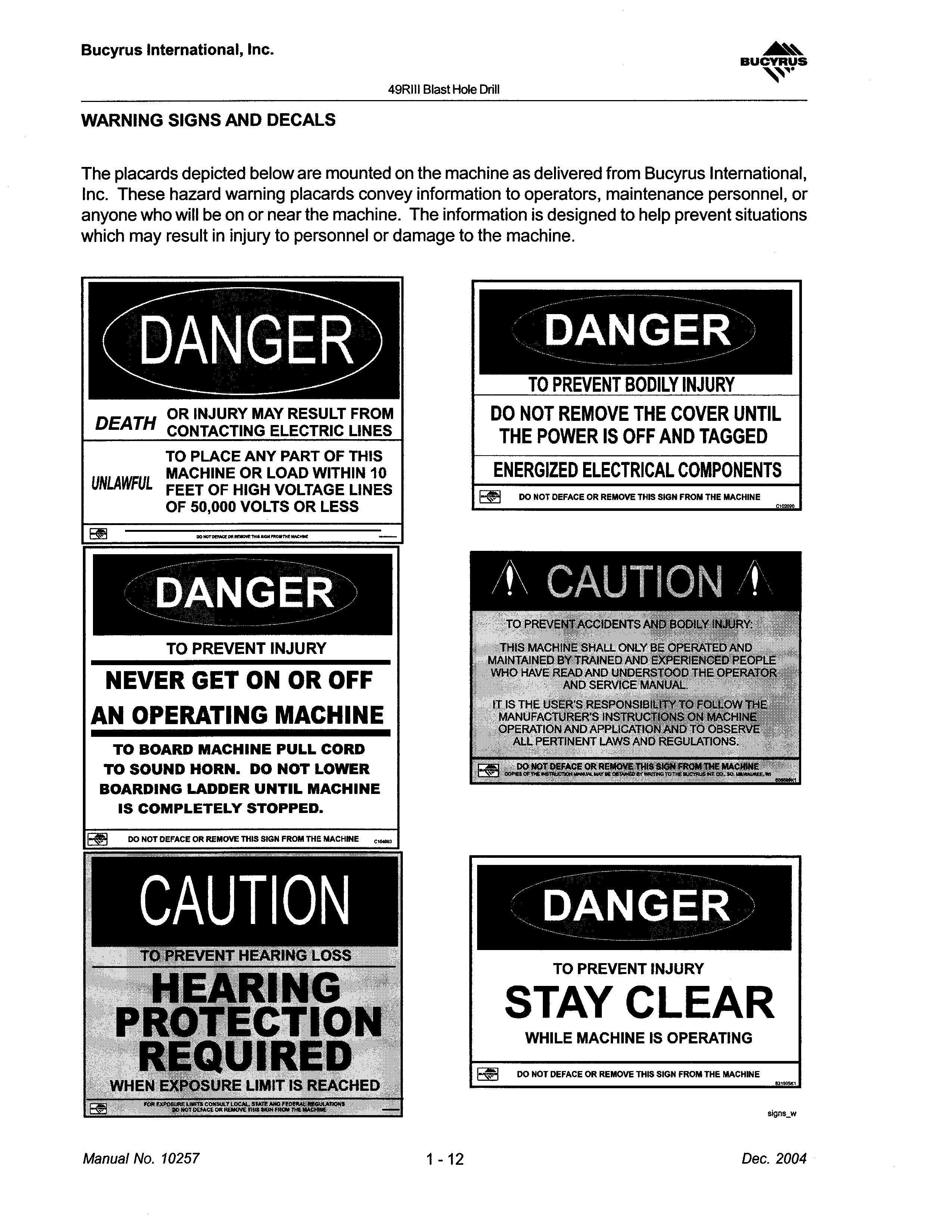
OR INJURY MAY RESULT FROM DEATH CONTACTING ELECTRIC LINES TO PLACE ANY PART OF THIS MACHINE OR LOAD WITHIN 10 UNLAWFUL FEET OF HIGH VOLTAGE LINES OF 50,000 VOLTS OR LESS
TO PREVENT BODILY INJURY DO NOT REMOVE THE COVER UNTIL THE POWER IS OFF AND TAGGED ENERGIZED
TO PREVENT INJURY NEVER GET ON OR OFF AN OPERATING MACHINE TO BOARD MACHINE PULL CORD TO SOUND HORN. DO NOT LOWER BOARDING LADDER UNTIL MACHINE IS COMPLETELY STOPPED.

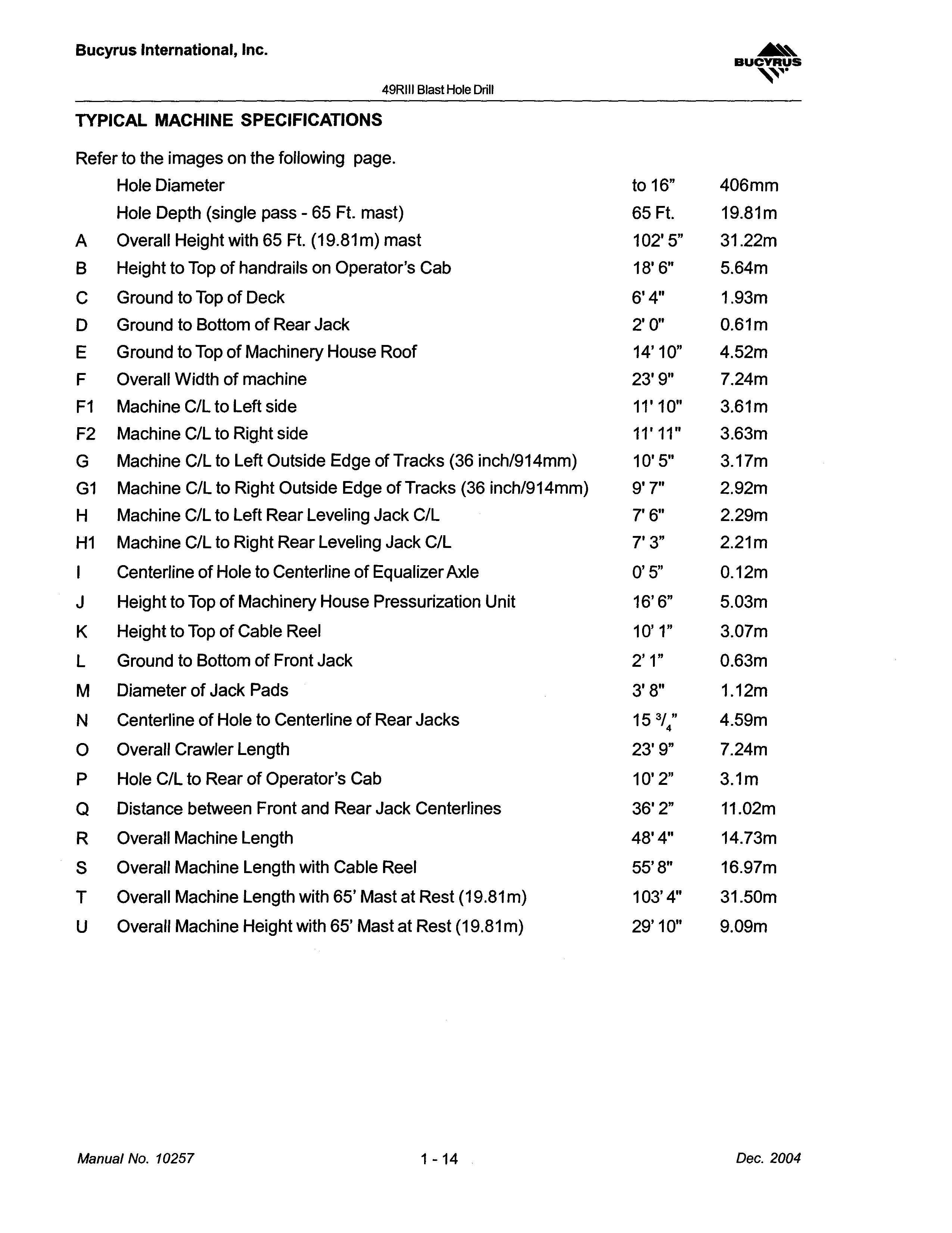
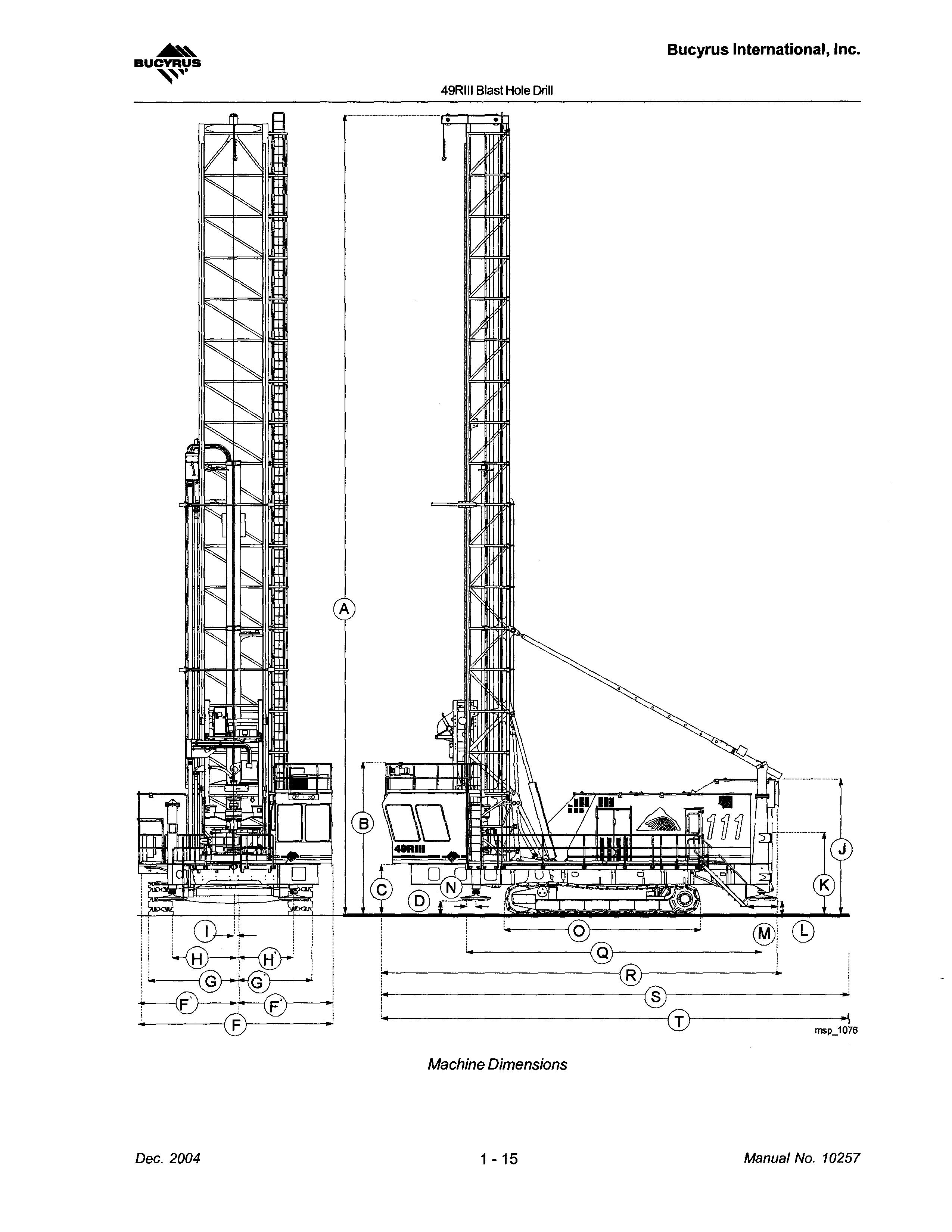
TYPICAL MACHINE SPECIFICATIONS
Refer to the images on the following page.
Blast Hole
MACHINE OVERVIEW
MACHINE OVERVIEW
This machine is designed and constructed to provide efficient service under the most severe conditions. It is built to the highest possible standards and will provide trouble free operation if properly maintained.
This machine is designed and constructed to efficient service under the most severe conditions. It is built the highest possible standards and will provide trouble operation if properly maintained.
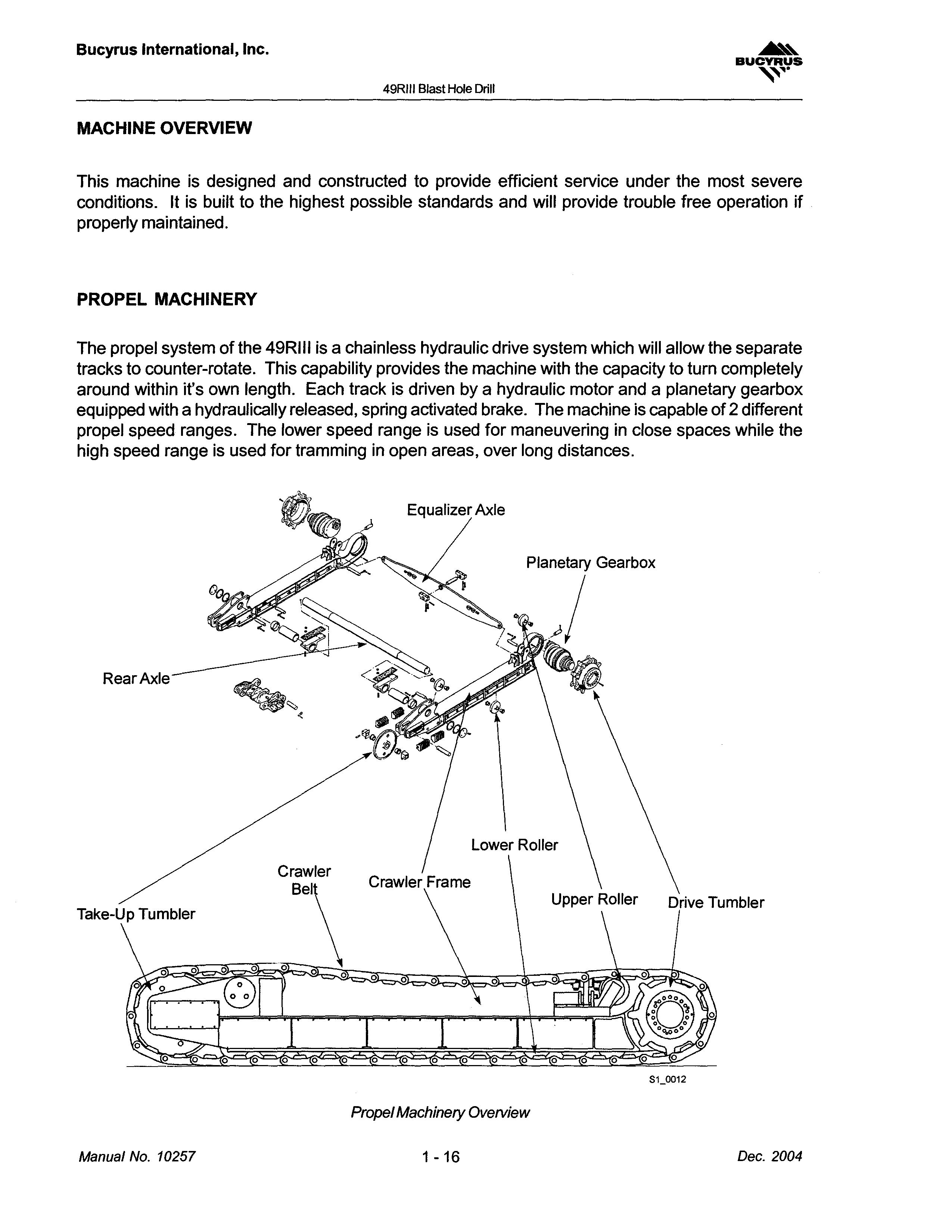
PROPEL MACHINERY
PROPEL
propel system the 49RIII a hydraulic drive will separate provides machine capacity to around it's track hydraulic motor equipped with a hydraulically activated machine 2 different speed ranges. speed for in close high range is for in open areas, over distances.
The propel system of the 49RIII is a chainless hydraulic drive system which will allow the separate tracks to counter-rotate. This capability provides the machine with the capacity to turn completely around within it's own length. Each track is driven by a hydraulic motor and a planetary gearbox equipped with a hydraulically released, spring activated brake. The machine is capable of 2 different propel speed ranges. The lower speed range is used for maneuvering in close spaces while the high speed range is used for tramming in open areas, over long distances.
49RIII Blast Hole Drill
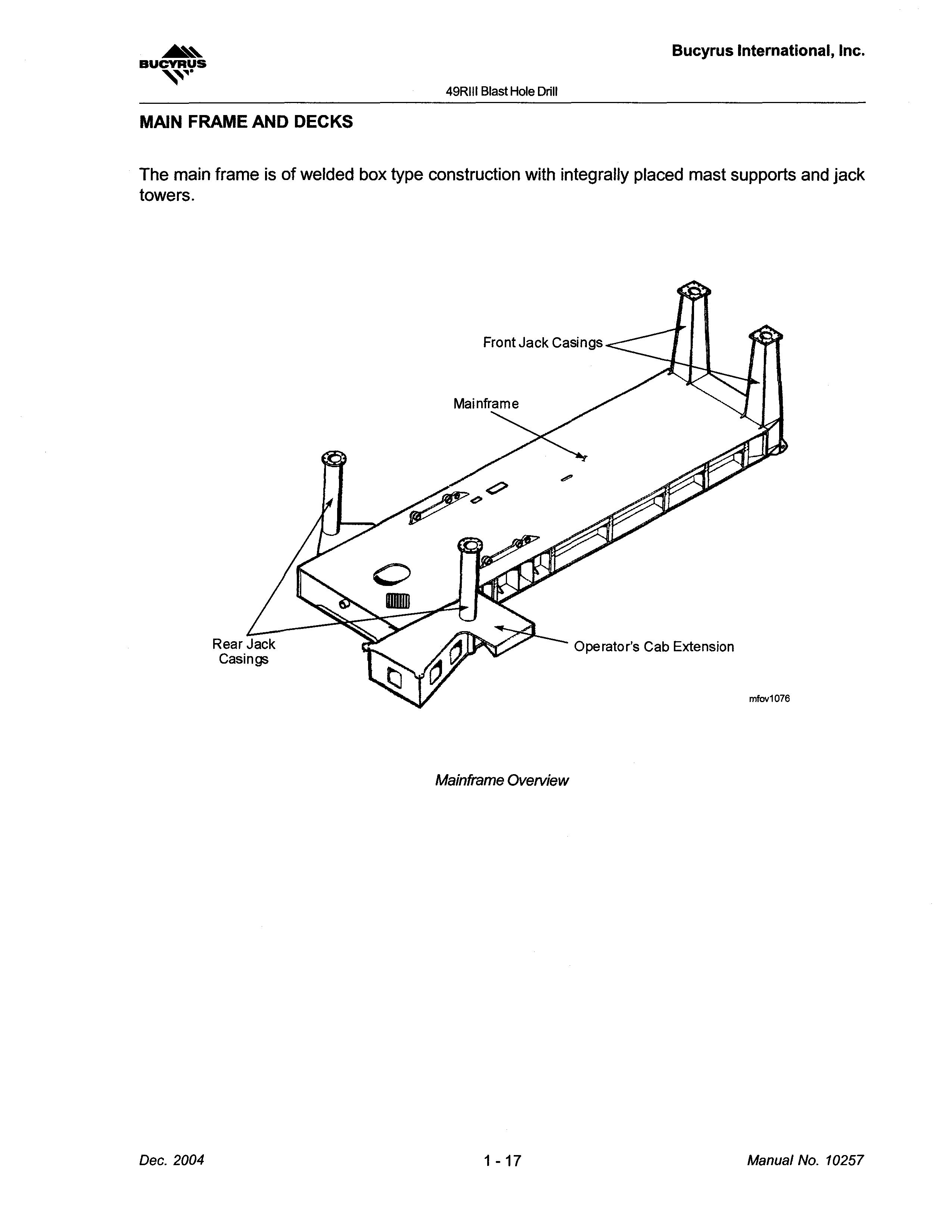
MAIN FRAME AND DECKS
The main frame is of welded box type construction with integrally placed mast supports and jack towers.
Operator's Cab Extension
mfov1076
Mainframe Overview
Blast
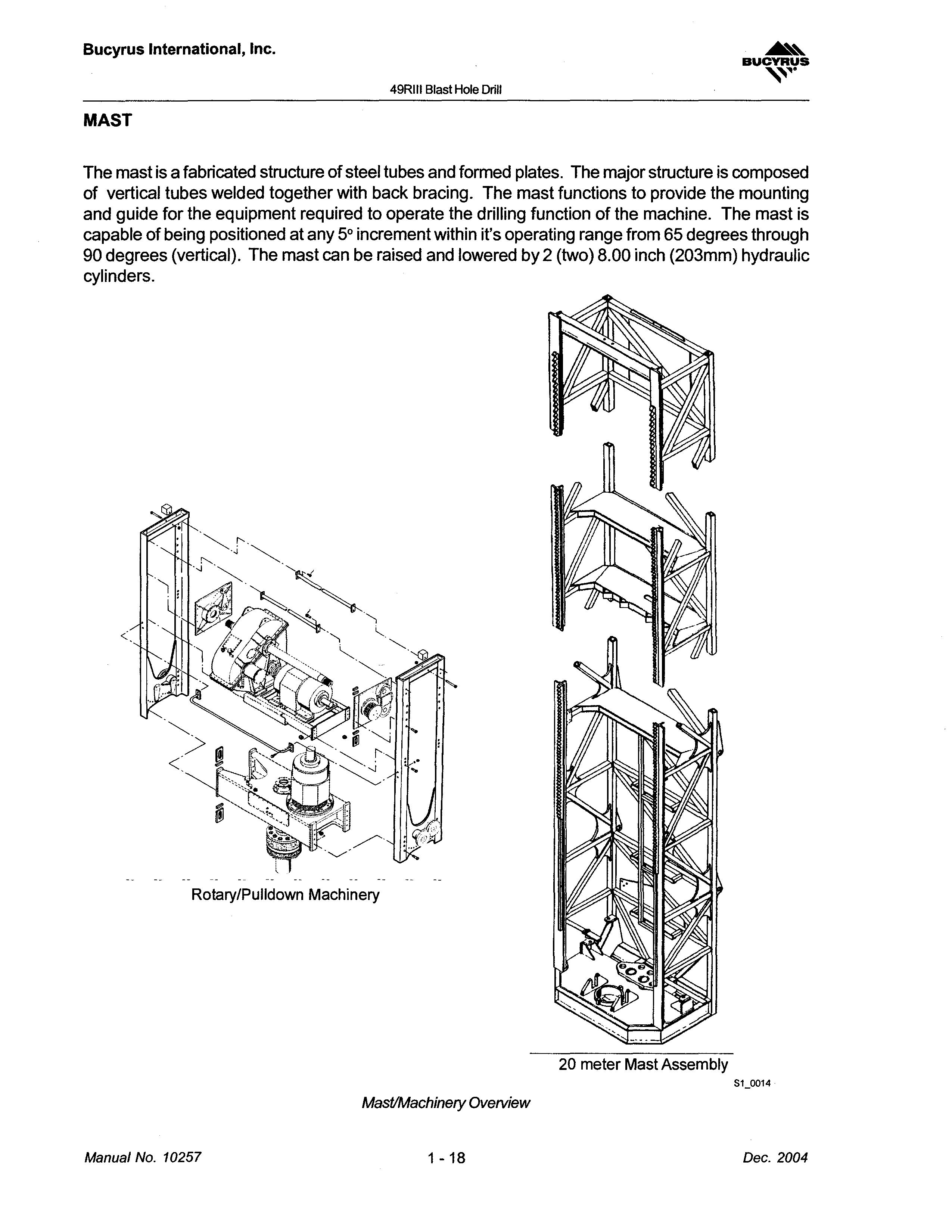
MAST
The mast is a fabricated structure of steel tubes and formed plates. The major structure is composed of vertical tubes welded together with back bracing. The mast functions to provide the mounting and guide for the equipment required to operate the drilling function of the machine. The mast is capable of being positioned at any 5° increment within it's operating range from 65 degrees through 90 degrees (vertical). The mast can be raised and lowered by 2 (two) 8.00 inch (203mm) hydraulic cylinders.
mast fabricated structure of tubes formed is composed vertical together with back bracing. the mounting guide to operate the drilling machine. mast is capable of at any 5° increment within it's range from 65 degrees through 90 degrees The mast can be raised and lowered 2 8.00 inch cylinders.
Rotary/Pulldown
81_0014
2004
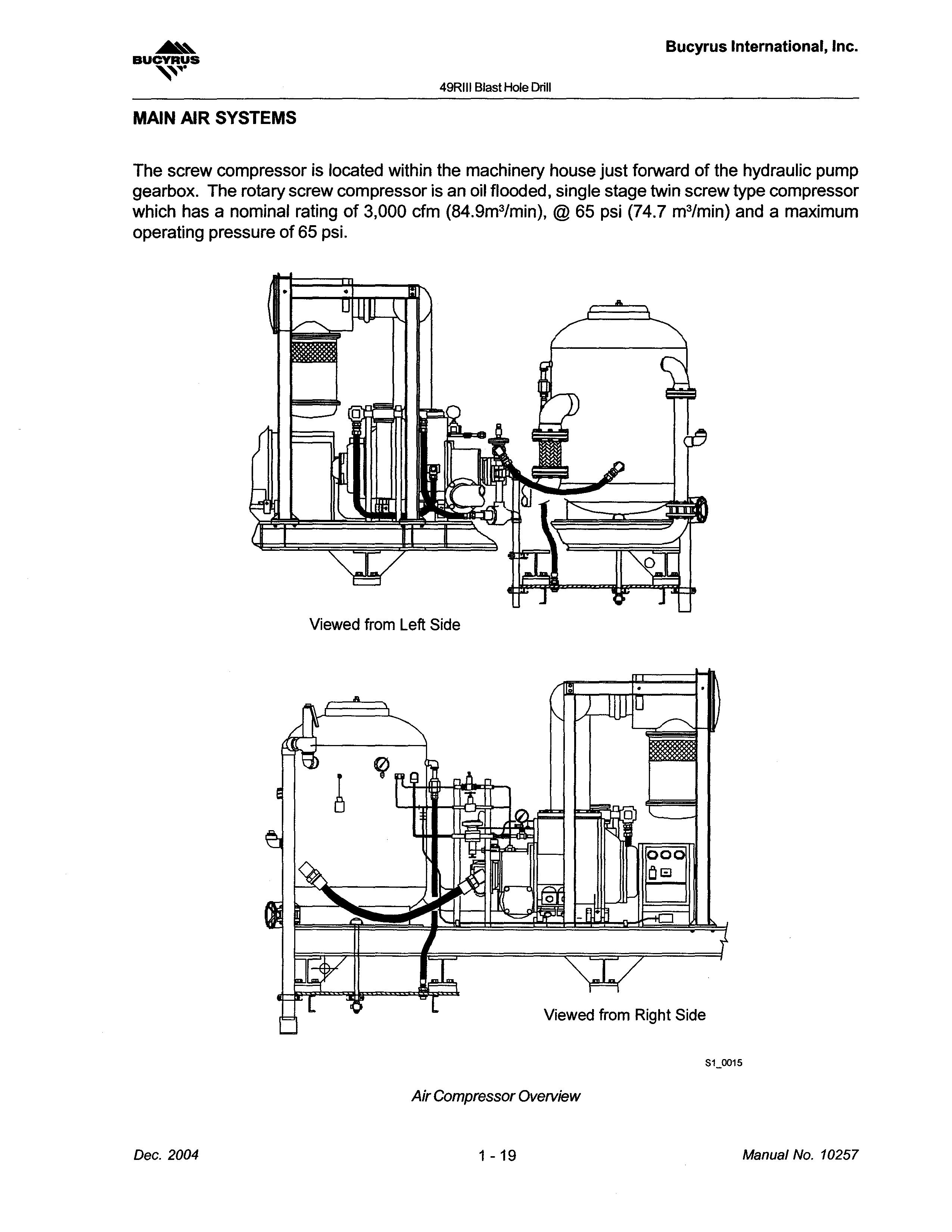
MAIN AIR SYSTEMS
The screw compressor is located within the machinery house just forward of the hydraulic pump gearbox. The rotary screw compressor is an oil flooded, single stage twin screw type compressor which has a nominal rating of 3,000 cfm (84.9m 3/min), @ 65 psi (74.7 m 3 /min) and a maximum operating pressure of 65 psi.
screw is
HYDRAULIC SYSTEM
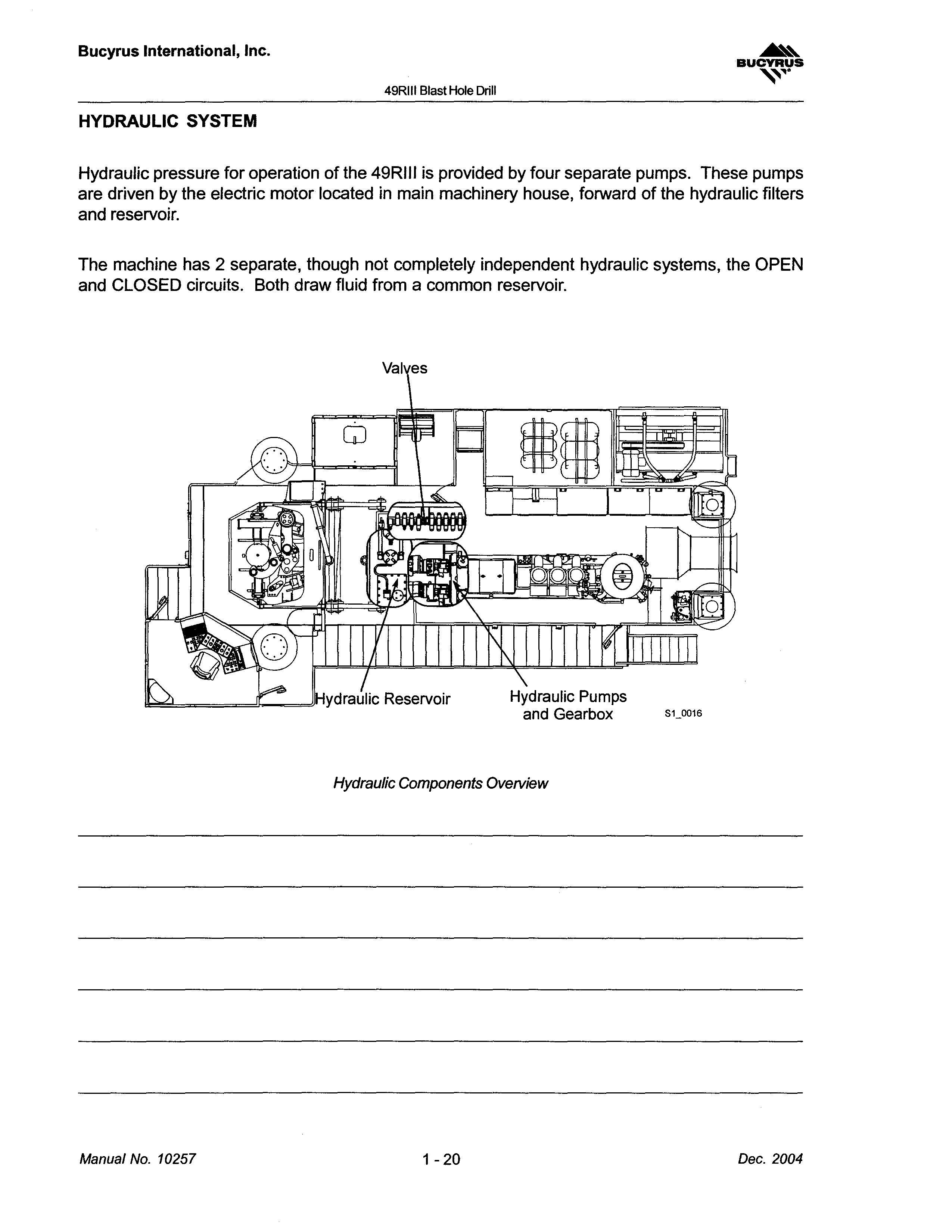
Hydraulic pressure for operation of the 49RIII is provided by four separate pumps. These pumps are driven by the electric motor located in main machinery house, forward of the hydraulic filters and reservoir.
The machine has 2 separate, though not completely independent hydraulic systems, the OPEN and CLOSED circuits. Both draw fluid from a common reservoir.
Drill Hydraulic by are driven the electric motor located main forward of the filters and reservoir. a common
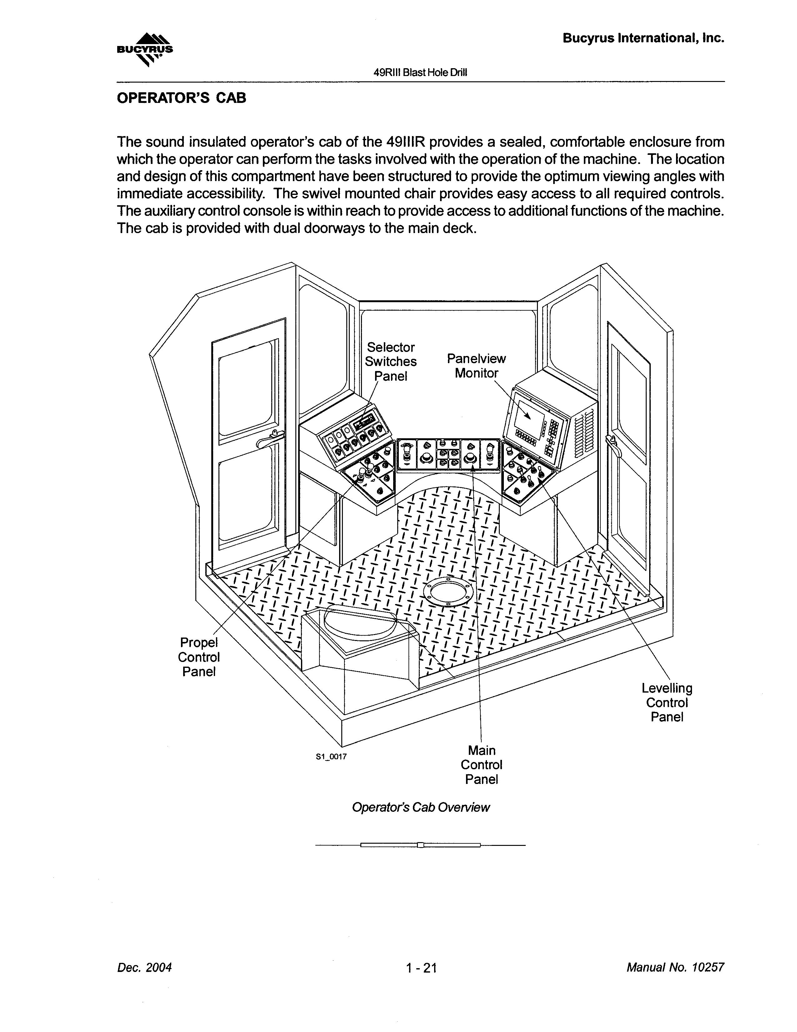
OPERATOR'S CAB
The sound insulated operator's cab of the 49111R provides a sealed, comfortable enclosure from which the operator can perform the tasks involved with the operation of the machine. The location and design of this compartment have been structured to provide the optimum viewing angles with immediate accessibility. The swivel mounted chair provides easy access to all required controls. The auxiliary control console is within reach to provide access to additional functions of the machine. The cab is provided with dual doorways to the main deck.

• Thank you very much for reading the preview of the manual.
• You can download the complete manual from: www.heydownloads.com by clicking the link below
• Please note: If there is no response to CLICKING the link, please download this PDF first and then click on it.