GENERAL INFORMATION
remove the key, spring retainer, springs and tumblers and reassemble correctly.
1-7
TUMBLER TUMBLER
NOTE: If the tumblers have not been assembled correctly, they can be removed from the cylinder by holding cylinder with the tumbler slots down, pulling the side bar out with the fingers and jarring the cylinder to shake the tumblers out. This procedure is necessary because once the tumblers have been pressed down into the cylinder they are held in their slots by the side bar.
4 TUMBLER CYLINDER
5 TUMBLER CYLINDER LOCK CYLINDER RETAINER ( LOCKING DEVICE )
6. If, after checking, it is found that the lock cylinder is assembled properly, remove key and secure cylinder in a vise with spring retainer exposed. NOTE: Use leather or wood at each vise jaw to prevent damage to the cylinder. 7. Using a suitable staking tool, stake the spring retainer securely in place by staking the cylinder metal over the retainer at each end. Refer to Figure 1-6.
2756
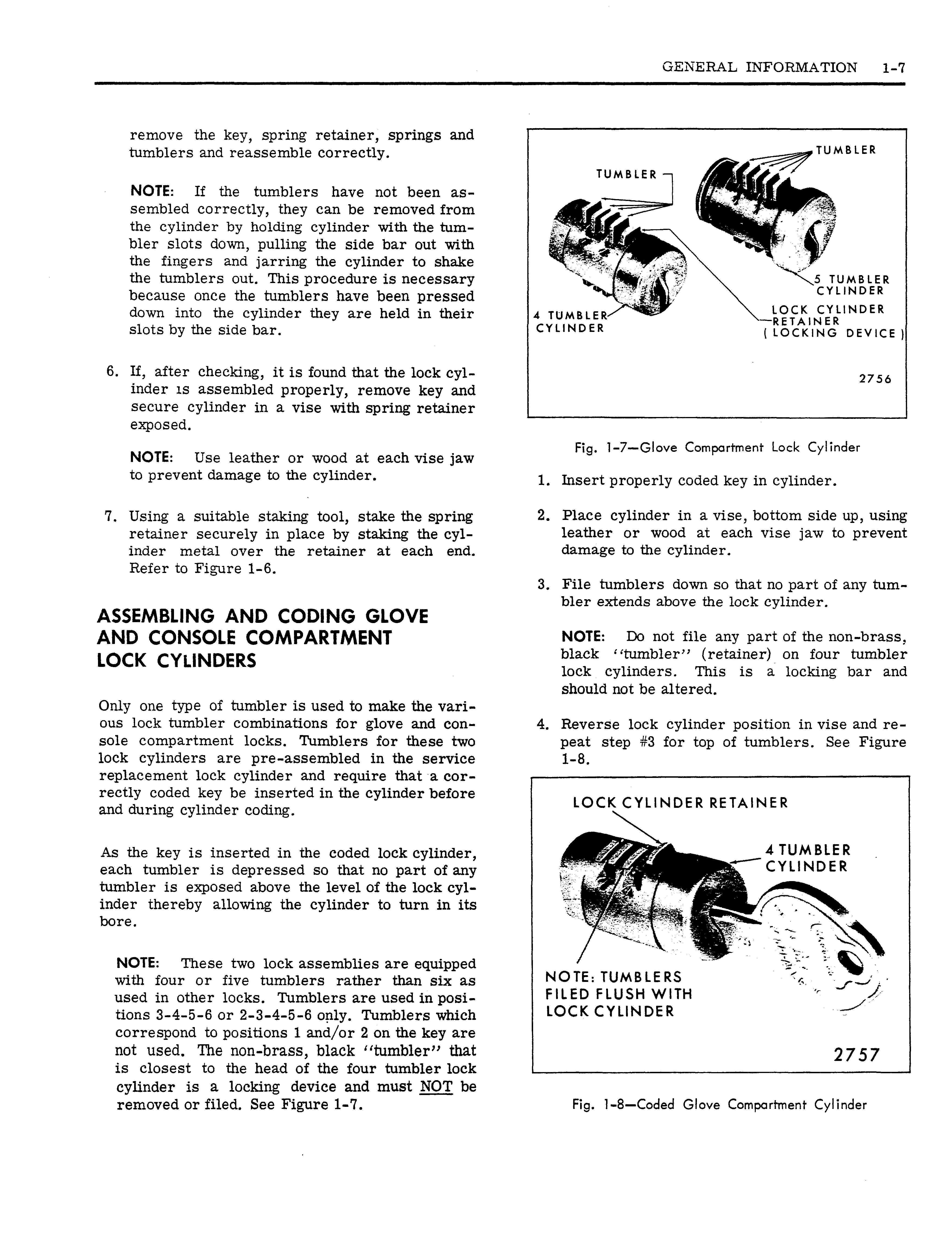
Fig. 1-7—Glove Compartment Lock Cylinder
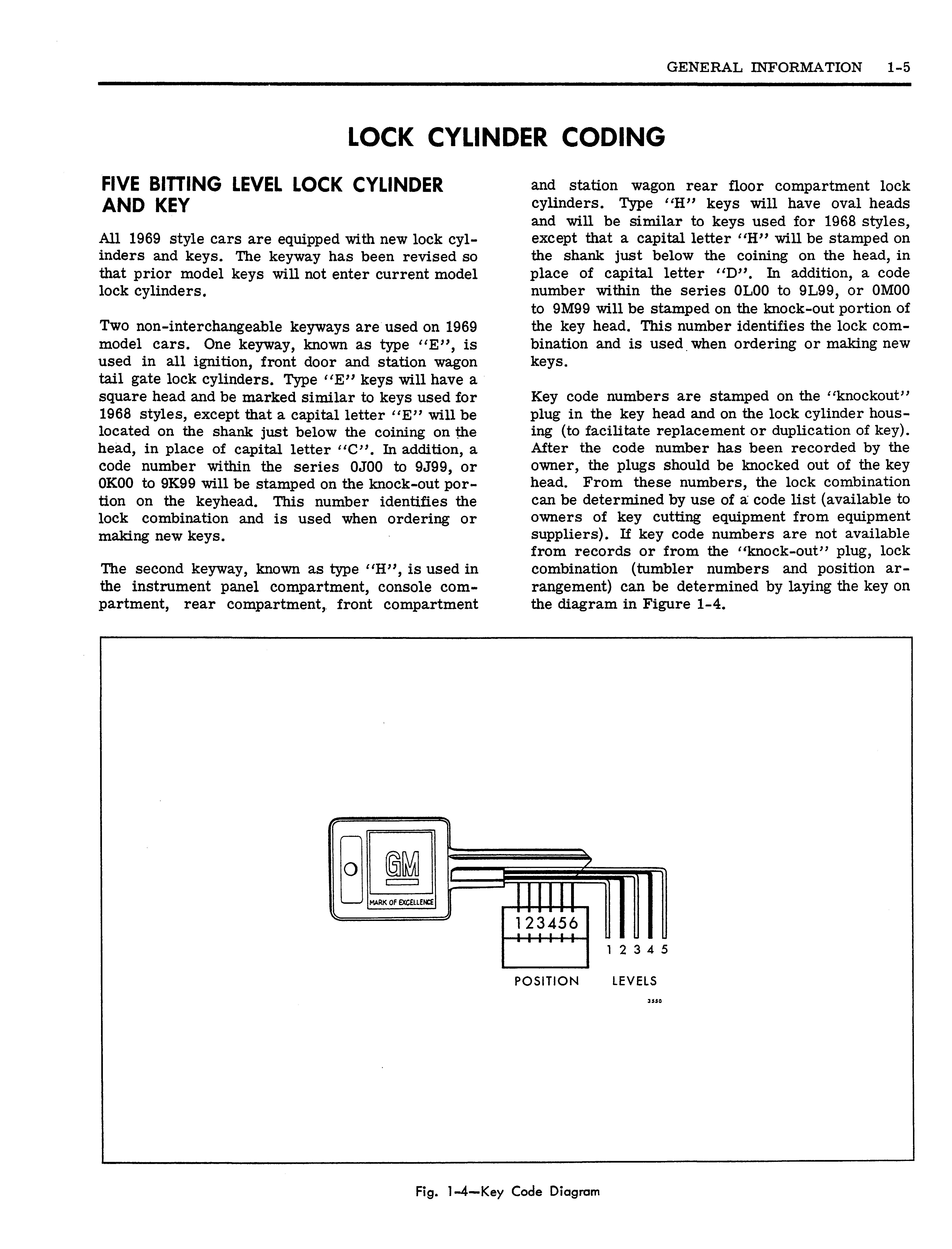
1. Insert properly coded key in cylinder. 2. Place cylinder in a vise, bottom side up, using leather or wood at each vise jaw to prevent damage to the cylinder. 3. File tumblers down so that no part of any tumbler extends above the lock cylinder.
ASSEMBLING AND CODING GLOVE AND CONSOLE COMPARTMENT LOCK CYLINDERS Only one type of tumbler is used to make the various lock tumbler combinations for glove and console compartment locks. Tumblers for these two lock cylinders are pre-assembled in the service replacement lock cylinder and require that a correctly coded key be inserted in the cylinder before and during cylinder coding.
NOTE: Do not file any part of the non-brass, black "tumbler" (retainer) on four tumbler lock cylinders. This is a locking bar and should not be altered. 4. Reverse lock cylinder position in vise and repeat step #3 for top of tumblers. See Figure 1-8. LOCK CYLINDER RETAINER
As the key is inserted in the coded lock cylinder, each tumbler is depressed so that no part of any tumbler is exposed above the level of the lock cylinder thereby allowing the cylinder to turn in its bore. NOTE: These two lock assemblies are equipped with four or five tumblers rather than six as used in other locks. Tumblers are used in positions 3-4-5-6 or 2-3-4-5-6 only. Tumblers which correspond to positions 1 and/or 2 on the key are not used. The non-brass, black "tumbler" that is closest to the head of the four tumbler lock cylinder is a locking device and must NOT be removed or filed. See Figure 1-7.
4 TUMBLER CYLINDER
NOTE: TUMBLERS FILED FLUSH WITH LOCK CYLINDER
2757 Fig. 1-8—Coded Glove Compartment Cylinder