
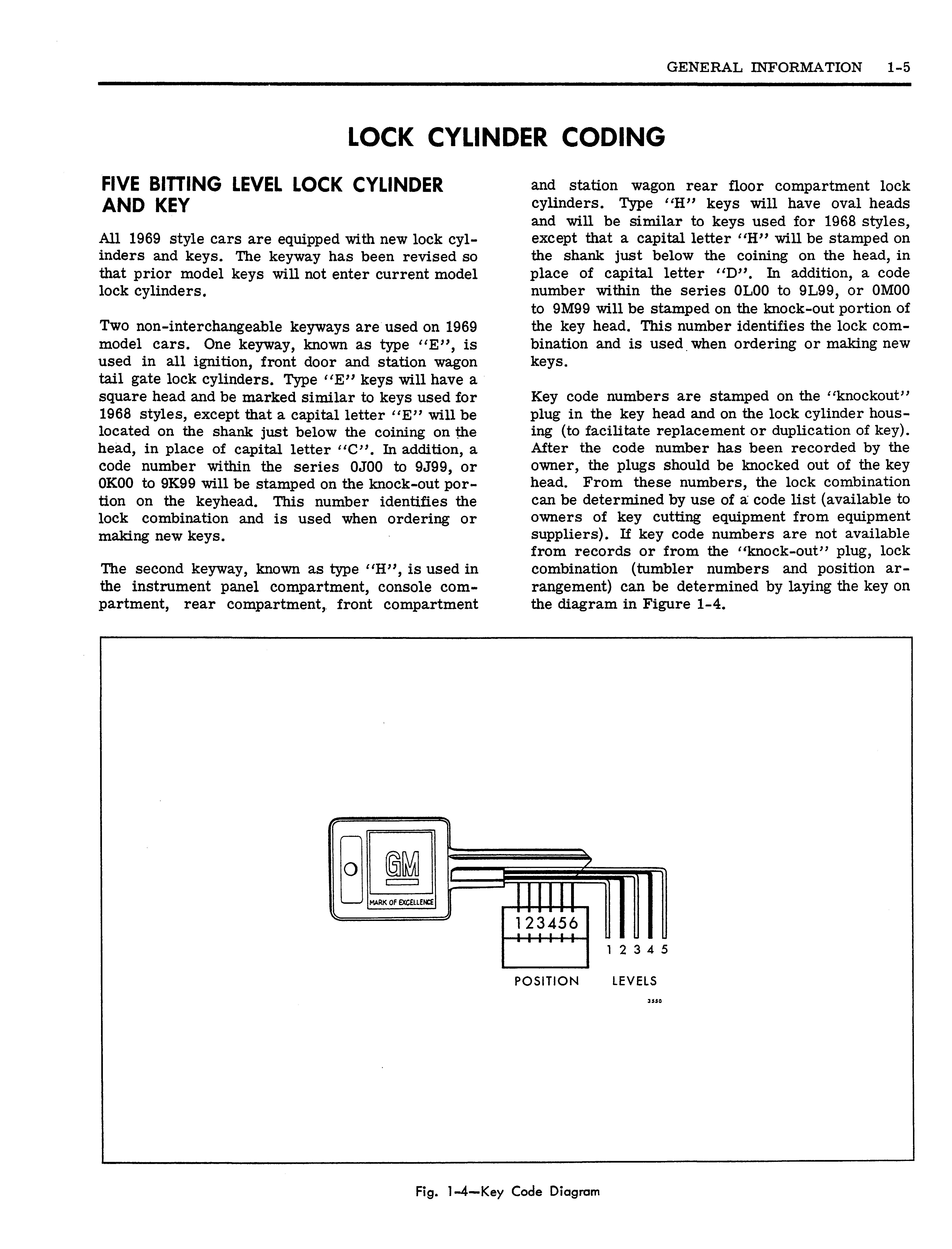
30 minute read
After tumbler numbers and arrangement

remove the key, spring retainer, springs and tumblers and reassemble correctly.
NOTE: If the tumblers have not been assembled correctly, they can be removed from the cylinder by holding cylinder with the tumbler slots down, pulling the side bar out with the fingers and jarring the cylinder to shake the tumblers out. This procedure is necessary because once the tumblers have been pressed down into the cylinder they are held in their slots by the side bar.
6. If, after checking, it is found that the lock cylinder is assembled properly, remove key and secure cylinder in a vise with spring retainer exposed.
NOTE: Use leather or wood at each vise jaw to prevent damage to the cylinder.
7. Using a suitable staking tool, stake the spring retainer securely in place by staking the cylinder metal over the retainer at each end.
Refer to Figure 1-6.
ASSEMBLING AND CODING GLOVE AND CONSOLE COMPARTMENT LOCK CYLINDERS
Only one type of tumbler is used to make the various lock tumbler combinations for glove and console compartment locks. Tumblers for these two lock cylinders are pre-assembled in the service replacement lock cylinder and require that a correctly coded key be inserted in the cylinder before and during cylinder coding.
As the key is inserted in the coded lock cylinder, each tumbler is depressed so that no part of any tumbler is exposed above the level of the lock cylinder thereby allowing the cylinder to turn in its bore.
NOTE: These two lock assemblies are equipped with four or five tumblers rather than six as used in other locks. Tumblers are used in positions 3-4-5-6 or 2-3-4-5-6 only. Tumblers which correspond to positions 1 and/or 2 on the key are not used. The non-brass, black "tumbler" that is closest to the head of the four tumbler lock cylinder is a locking device and must NOT be removed or filed. See Figure 1-7.
TUMBLER TUMBLER
4 TUMBLER CYLINDER 5 TUMBLER CYLINDER
LOCK CYLINDER
RETAINER ( LOCKING DEVICE )
2756
Fig. 1-7—Glove Compartment Lock Cylinder
1. Insert properly coded key in cylinder.
2. Place cylinder in a vise, bottom side up, using leather or wood at each vise jaw to prevent damage to the cylinder.
3. File tumblers down so that no part of any tumbler extends above the lock cylinder.
NOTE: Do not file any part of the non-brass, black "tumbler" (retainer) on four tumbler lock cylinders. This is a locking bar and should not be altered.
4. Reverse lock cylinder position in vise and repeat step #3 for top of tumblers. See Figure 1-8.
LOCK CYLINDER RETAINER
4 TUMBLER CYLINDER
NOTE: TUMBLERS FILED FLUSH WITH LOCK CYLINDER
2757
Fig. 1-8—Coded Glove Compartment Cylinder
GLASS POLISHING
REMOVAL OF MINOR SCRATCHES AND ABRASIONS
Description
Minor glass scratches and abrasions can be effectively removed or substantially reduced by utilizing the procedure and precautions presented in this section. The phases of glass polishing discussed in this section include the equipment required, the recommended procedure and the precautions necessary.
There are two. basic types of automotive glass: (1) laminated safety plate (all windshield and skylight glass) and (2) solid tempered safety plate (all side windows and back glass, except skylight).
A major concern in glass polishing is preventing double vision from developing in areas that will distort driver's vision. Eor this reason, less polishing can be done on the windshield in the driver's line of vision than in other areas. Dis- • tortion is most likely to result when attempting to remove deep scratches.
Glass polishing is an operation that must be performed with reasonable care.
The equipment and procedures recommended here were developed using cerium oxide compound (Glass-Nu or equivalent). Follow the manufacturer's directions if other materials are used.
The following equipment is recommended for glass polishing:
1. A low speed (600-1300 RPM) rotary polisher (Skil Model #570 or equivalent).
2. A wool felt rotary-type polishing pad, approximately three inches in diameter and two inches thick.
3. Powdered cerium oxide (Glass-Nu or equivalent) mixed with water as the abrasive compound.
4. A wide mouth container to hold, the polish.
Glass Polishing Procedure
1. Mix at least three heaping tablespoons of cerium oxide (Glass-Nu or equivalent) with sufficient water to obtain a cream y consistency. pound cakes on the felt pad faster. If a small proportion is used the polishing time required will increase.
2. Agitate the mixture occasionally to maintain a creamy consistency. The powdered cerium oxide is insoluable in water and tends to separate.
3. Draw a circle around the scratches on the inside of the windshield with- a marking crayon or equivalent. Draw other lines directly behind scratches to serve as guides in locating the scratch during polishing (Fig. 1-9).
HOLD PAD FLAT AGAINST GLASS

Fig. 1-9—Minor Glass Scratch Removal
4. Use masking paper where needed to catch drippings or spattered polish.
5. Dip the felt pad attached to the polisher into the mixture several times to insure that the pad is well saturated.
NOTE: Never submerge or allow the pad to stay in the mixture as it may loosen the bond between the pad and the metal plate. 6. Using moderate, but steady, pressure, hold the pad flat against the scratched area of the glass, and with a feathering-out motion, polish the affected area as shown in Figure 1-9.
NOTE: Avoid excessive pressure which does not speed-up the operation and may cause overheating of the glass.
7. Cover a sufficient area around the scratch with a feathering-out motion as shown in Figure 1-9, to eliminate any possibility of a "bulls-eye".
NOTE: Never hold the tool in one spot or operate the tool on the glass any longer than 30 to 45 seconds at a time. If the glass becomes hot to touch, let it air cool before proceeding further. Cooling with cold water may crack the heated glass. 1969 model station wagons. Both types incorporate a pressure sensitive adhesive. In addition, both transfers are designed with the same Burgundy containing a flattening agent. Due to the difference to be inter-mixed on the same car. service parts department. When placing orders for transfers, carefully observe "Division", "Model in temperatures below 65°F. clean water. surface. Deviating from specifications, such as
8. Dip the pad into the mixture about every fifteen seconds to insure that the wheel and the glass are always wet during the polishing operation. A dry pad causes excessive heat to develop.
9. After removing the scratch or abrasion, wipe the body clean of any polish.
10. Clean the polishing pad.
NOTE: Care should be taken during polishing and storage to keep the pad free of foreign
WOOD GRAIN TRANSFER (Station Wagon Styles)
DESCRIPTION AND GENERAL INFORMATION

Two types of vinyl wood grain transfers are used on Walnut wood grain pattern, the same colors, and the same 50° or semi-gloss finish. One transfer is of all-vinyl construction. The other transfer is a heavier gauge material and is also of vinyl construction, but is top coated with a clear acrylic in construction, the two types of transfers are not
Both types of transfers are available through the Year" and "body style" identification to determine the correct part number.
The following general information and procedures apply to both types of transfers. For quality installation of service replacement transfers, the temperature of the transfer, the panel surface and the work room should be between 65°F. and 90°F. Transfers should not be replaced Prepare a supply of wetting solution, as called out in the procedure, by adding 1/4 ounce of detergent ("Joy", "Vel", or equivalent) to one gallon of
Use of a wetting solution, as specified, insures a better bond between the transfer and the painted material such as dirt, metal filings, etc.
using too much detergent or using a soap solution, is detrimental to the bond of the transfer. or damage to the underlying acrylic paint finish requires that the metal repair and/or refinish operations be carried to completion before a transfer is installed.
The purpose of squeegeeing with a proper tool, using progressive, overlapping strokes and working from the center outwardly, is to drive out all the water and air. At the same time, proper squeegeeing provides the required pressure per square inch for proper bonding of pressure sensitive adhesive to painted surfaces. Scuff-sanding an acrylic finish before transfer installation with #360 or #400 sandpaper promotes better adhesion, and removes dirt nibs and high spots. The following equipment and materials are necessary in making a quality transfer installation. Equivalent products can be used. 1. Liquid detergent: "Joy", "Vel" or equivalent
2. Wax and Silicone Remover: "Prep-Sol", "Pre
Kleano", or "Acryli Clean"
3. 3-M Vinyl Trim Adhesive or equivalent; brush or spray-can 4. Squeegee: 3" to 5 M wide; plastic or hard rubber
5. Water bucket and sponge
6. Sandpaper, #360 or #400, Wet-or-Dry Type
7. Infra-red heat bulb and extension cord
8. Clean wiping rags or paper towels
9. Sharp knife
Removal 1. Wash and clean repair surfaces and adjacent panels and openings as required.
2. Remove transfer finishing moldings, handles, side marker lamps, and/or other transfer overlapping parts.
3. Remove affected transfer by starting at one edge and by peeling transfer as sheet from surface. Application of heat to affected transfer at point of removal aids removal operation.
CAUTION: Avoid using pointed or sharp instruments during transfer removal as they may damage paint finish.
Installation
1. Scuff-sand acrylic painted surface with #360 or #400 sandpaper by dry sanding. Freshly painted surfaces must be thoroughly dry. Residual solvents in fresh paint may lead to subsequent blistering problems.
2. Clean acrylic painted surface with wax and silicone remover, such as: Prep-Sol; Pre
KLeano; Acryli-Clean; or equivalent. Wipe surface dry with clean cloth. Use compressed air to blow away loose dirt from area of repair.
3. Apply vinyl trim adhesive to door hem flanges and to rear body lock pillar facing that will be covered by transfer.
4. Peel paper backing from transfer and lay transfer, face down, on clean table.
5. Using clean sponge, apply ample wetting solution to transfer adhesive and to repair panel surface.
6. Align upper edge and ends of transfer with panel surface and press down lightly across top.
7. Squeegee outboard from middle to edges of transfer removing all air bubbles and wetting
G solution to assure bonding of film to painted surface. On large transfers, the following sequence of operations will simplify transfer installation.
a. Squeegee a short, 4 to 6 inch, horizontal section of transfer at center of panel. Lift right or left side of transfer, position it straight and close to panel, and squeegee toward lifted edge. Avoid stretching transfer at lifted end. Squeegee progressively from middle with firm, overlapping strokes.
b. Lift upper area of transfer (up to bonded area of step "a" above) and, working upward from bonded section at middle, squeegee transfer into place.
c. Lift lower area of transfer (up to bonded area) and, working downward from bonded section at middle, squeege transfer into place.
CAUTION: If a wrinkle is trapped during squeegeeing operations, carefully lift the affected transfer section. Align the affected section to the surface and progressively squeegee it into place. Do not lift the transfer if only a few tiny bubbles are trapped.
d. Secure opposite half of transfer to surface as described in steps "a" "b" and "c". above.

8. Notch out peak or curved edges of transfer where necessary. In some cases it may be necessary to trim off excess material at edges.
9. Heat inboard side of door hem flanges (or body lock pillar facing, etc.) and edges of transfer film (to approximately 90°F.).
10. Fold ends of transfer over door hem flanges (or over corners at panel ends) and press to secure edges of transfer to panel surfaces.
Avoid undue pulling or stretching at ends as tearing could result.
11. Apply heat to transfer at door handle holes, side marker lamps and other depressions.
Press transfer uniformly into depressions to obtain formed bond.
12. Carefully cut out transfer at side marker lamps, door handle holes, and other openings in panel.
13. Inspect transfer installation from critical angle using adequate light reflection to detect any irregularities that may have developed during installation. Remove all air or moisture bubbles by piercing each at an acute angle with a fine pin or needle and by pressing the bubble down.
14. Install previously removed parts and clean up car as required.
INTRODUCTION
PAINT CONDITIONS
Painters should be able to recognize paint conditions that occur on acrylics in order to be able to repair the conditions properly and thereby produce quality work. Understanding the cause and severity of a given condition is an aid to the painter in determining the best repair procedure. Many of the paint conditions that may be encountered are described and illustrated alphabetically in the following:
BLISTERING

Blistering is the bubbling or raising of the paint surface. When dry and rubbed or sanded, blisters may give a pitted appearance down to the undercoat or even to the bare metal.
Fig. 1-11—Blushing
Correction: In most cases, spraying a coat of high grade thinner with 10% to 20% retarder immediately over affected area will dissolve the blushed acrylic and restore normal appearance of the finish. If blushed color dries, add retarder to reduced material and color coat as
BULL'S-EYE
Fig. 1-10—Blistering
Cause: This condition is usually caused by moisture becoming trapped between metal and undercoat or between undercoat and color coat, expanding and forming small or large rounded blisters.
Correction: In minor cases the blister may be sanded out, resurfaced, sanded, and refinished. In severe cases however, the finish must be removed down to the metal before refinishing.
BLUSHING
required.
A milky or dull mist formation on the surface.
Cause: Blushing is caused by precipitation of the acrylic finish, due to condensation of moisture on the applied wet acrylic film. Rainy or humid weather at refinishing time is the usual cause of this condition.
Fig. 1-12-Bull's-Eye A spotted, ringed, outline or low area in the color coat. It often gives the illusion of a different color, depending upon the peculiarities of light and shadows in the area. Primer might show.
Cause: A bull's-eye is the result of undercoat shrinkage; incomplete spot repair; or poor technique.
Correction: In minor cases, sand with No. 600 sandpaper and polish. In extreme cases, sand and featheredge the area correctly, build up the paint surface with undercoat, then color coat as required.
LINE-CHECKING
Fig. 1-13—Line-Checking
This appears as a series of straight lines of various configurations. Depending on the thickness of the color and the severity of the condition, the checking lines may be quite short or as long as 18 inches.
Cause: This may be due to excessively thick color coats; or application of new color over old color which checked before and was not removed completely.
Correction: Remove the checked color coat in the affected area to the undercoat and recolor coat as required. Original undercoats are not affected by line-checking.
CHEMICAL DISCOLORATION
This is a condition that can occur on solid or metallic colors and is evidenced by contrasting color spots appearing mostly on flat or horizontal surfaces. On red metallics, the spots are darker red; on blue metallics, the spots are darker blue; etc. On solid colors, the discoloration spots may be of any color depending upon specific conditions.
Cause: On metallic colors the condition apparently is caused by fall-out or moisture in the form of rain water containing acid or alkaline materials- which' attack the aluminum flake. On solid colors, specific pigments may be affected by specific materials from fall-out.
Correction: In mild cases, rub out and polish. In severe cases, sand to remove the condition and color coat as required. The bes t prevention against this condition is to keep the paint finish clean and polished.
CRAZING
Fig. 1-15-Crazing.

Crazing usually appears as a fine spider-web type of cracking in the color coat. The cracks may vary from very fine (requiring a magnifying glass) to relatively coarse.
The crack-lines connect to one another. Crazing occurs' immediately after repairs are attempted.
Cause: Crazing occurs when excessive stresses, which occasionally may be set up in an acrylic color film during the time it cures, are suddenly released.
Prevention: Before repairs are attempted, test color to be repaired as follows: (1) Apply a drop of thinner to color in a most inconspicuous spot; (2) Allow thinner to evaporate and inspect color within thinner ring for crazing. A lack of crazing indicates that the color can be color coated or blended into normally. The appearance of crazing within the thinner ring indicates that the color must be removed down to the undercoat before repairs. Original factory undercoats are not affected by the crazing condition.
Correction: If a panel surface to be repaired already has the crazing condition, remove the complete affected color coat down to the factory undercoat and color coat as required.
DIRT IN PAINT
^r> ? VV V.<|^ : |vrT^g7 " "«
Fig. 1-16—Dirt in Paint
Surfaces with this condition have an uneven grittiness from lint, dirt, or sand-like particles.

Cause: Particles flying about and settling on wet paint film are the usual cause of this condition. In addition, surface edges and crevices that are not properly cleaned, blown out, or tacked off immediately before spraying will usually promote a dirt condition.
Correction: Rub or polish out with rubbing compound; or, in extreme cases, wet sand with No. 500 or No. 600 paper and rub out and polish.
DRY SPRAY
This can easily be distinguished by a certain uni
form, fine grittiness and dullness: It is usually in a linear pattern or a pattern of spray gun travel.
Cause: The condition is usually caused by holding the spray gun on an angle or too far from the surface. Insufficient thinner, excessive air pressure, dirty spray gun, or spraying in a draft can also cause dry spray conditions.
Correction: Minor cases of dry spray can usually be polished out. Major cases of dry spray must be sanded out and, if necessary, the surface color coated.
ETCHING
Etching is a very severe form of water spotting in which the entire paint surface within the periphery of each spot is etched or eaten away. The condition may appear as small or large water spotted areas and usually appears on the flat or horizontal surfaces. Etching penetrates much more deeply into the finish than water spotting.
Cause: The condition may be caused by bird droppings, insects, etc., in which case a strong chemical deposit is allowed to react with the finish for a prolonged period of time.
Correction: If the condition is "mild", sand to remove the condition and color coat as required. If the condition is "severe", sand to remove the condition; apply undercoats and color coats as required. The best prevention against this condition is to keep the paint surface clean and polished.
FISH-EYES
The appearance of small, crater-like openings in the finish after it has been applied.
Cause: Application of color coats over a surface contaminated with silicones.
Prevention:
1. Clean surface with wax and silicone removing agent such as Prep-Sol, Pre-Kleano, Acryli
Clean or equivalent.
2. Sand surface as required.
3. Re-clean surface with silicone removing agent.
4. Proceed with color coat application.
5. If above prevention steps are not successful and fish-eyes appear upon application of first coat, add "Fish-Eye Eliminator", "Fish-Eye
Preventer", or equivalent to reduced color and continue color coating immediately.
Correction: To repair a paint surface with the dried fish-eye condition, sand the surface smooth and color coat as required incorporating the above prevention steps.
MOTTLING
Wrong thinner mixtures, air pressures, spraying distance, film thickness, or spraying too wet or dry will also affect the color match, especially with metallic colors. The use of compounds too soon or burning the color coat by hard wheel polishing will also affect the color's appearance.
Old, waxed or polished areas will often appear different in color than areas with new color.
Correction: Sand only if necessary. Color coat with proper technique to nearest natural break
EXCESSIVE ORANGE PEEL
Fig. 1-18—Mottling
Mottling is a paint condition which appears as dark, shaded, or off-color spots and streaks in the paint finish. It is especially evident in metallic paints. A moderate amount of mottling is to be expected in metallic finishes.
Cause: Most colors are made from a combination of different pigments and metallic flakes which have varying densities and particle sizes, giving them a natural tendency to separate and float into groups when the film is in a liquid state. Under normal conditions, this tendency is small in magnitude and cannot be seen by the naked eye.
Certain conditions aggravate this to a point where the separation of the pigments and metallic flakes become visible, due to use of thinner which dries too slowly, allowing the pigment particles to migrate; or applying the color on a cold surface or in a cold room; or applying too heavy color coat.
Correction: In minor cases, no correction is required. In severe cases, clean and re-spray with color coat.
OFF-COLOR
line.
The color is off-shade or does not match.
Cause: The main cause of off-color conditions is not keeping the color coat thoroughly mixed.
Fig. 1-19—-Excessive Orange Peel

Orange peel is a natural occurrence in refinishing in which the resultant finish has uneven formations on the surface similar to that of an orange. A certain amount of orange peel occurs in normal refinishing and is acceptable.
Cause: Excessive orange peel is actually a defect of flow or leveling. Some of the causes are: using wrong type or a poor grade of thinner, using too high an air pressure, improper adjustment of spray gun, holding gun too far from surface or too close to surface, abnormal shop or metal temperatures, spraying in a draft, and coats applied too dry.
Correction: If condition is slight, no remedy is necessary. If condition is excessive, clean, compound, and polish affected area.
OVERSPRAY
The appearance of a rough or dull paint finish, similar to dry spray.
Cause: Overspray is caused by the settling of semi-dry paint particles on an adjacent finished surface during spraying operations.
color, compound and polish the affected area. If the condition involves two colors, but is slight, compounding and polishing the affected area may eliminate the condition. If the condition is severe, sand and color coat as required.
PIN-HOLING
Fig. 1-20—Pinhol ing
Pin-holing is a series of tiny, fine holes or pits that give the surface a spotty, dull, or off-shade appearance.

Cause: This condition is usually caused by solvent or air trapped in the paint film, plus heat.
Correction: Sand down the surface until it is smooth, and then color coat as required.
RUST SPOTS
Fig. 1-21-Rust Spots
or blister has broken, the rust begins to work back under the edges of the film. Since many primers are similar to rust in color, careful examination is necessary to identify the minor rust conditions accurately.
Cause: Moisture and chemicals attack the metal through either visible or microscopic breaks in the paint film, which usually result in blistering and peeling. Another cause is painting a metal surface containing rust that was not completely removed, or painting over metal touched by bare hands or chemical deposits from sanding water. ;
Correction: In minor cases, where the paint is not blistered, wash panel and clean rust stain off with body polish or a mild rubbing compound, hand-applied, then protect the finish with application of wax.
In severe cases the paint should be removed down to metal before cleaning the stains, so that no spots will be overlooked. Sand metal thoroughly to remove all traces of rust, treat surface with metal conditioner, dry and prime the areas as soon as possible to prevent the start of new rust
SAND OR FILE MARKS
formations. Refinish according to usual methods.
Rust spots are usually accentuated by a rust colored ring that forms at the affected area. Rusting beneath the film is usually made apparent by a raised section of film or a blister. After the film
Fig. 1-22—Sand or File Marks
The surface is grained or scratched.
Cause: File or disc marks were left in the metal, or the grit of the sandpaper used to sand the undercoat was too coarse.
Correction: Minor sand marks or scratches on the color coat may be lightly sanded and polished. In severe cases, sand and refinish as required.
SAND SCRATCH SWELLING
Fig. 1-23—Sand Scratch Swelling
Sand scratch swelling appears as exaggerated sandpaper scratches and occurs mostly after spot repairs or panel refinishing are done over sanded original acrylic finishes. The condition is most apparent on dark colors.
Cause: The condition is caused by sanding acrylic surfaces with coarse sandpaper preparatory to color coating. The thinner of fresh color coats swells the scratches to an enlarged size.
Prevention: Do not sand acrylics unless required. When sanding with coarse sandpaper is required, follow with extra-fine (No. 500 or No. 600) sandpaper. Then remove sand scratches by rubbing; or apply an approved sealer according to label directions before color coating.
Correction: Remove minor sand scratches by rubbing and polishing. In certain instances, water sanding with No. 500 or No. 600 sandpaper may be necessary before final rubbing and polishing. Remove severe sand scratches by employing steps outlined in "Prevention", above, and then color coat as required.
SWEAT OUT OR BLOOM
Usually characterized by a dull appearance along with some sand scratches.
Cause: Due to film shrinkage because of evaporation.
Correction: Polishing is usually sufficient to bring the gloss to an acceptable level. In severe cases where some film shrinkage has occurred that results in a slight wrinkled or orange peel appearance, sanding with No. 600 sandpaper and polishing may be required. THIN PAINT
Severe thin paint conditions are easily identified by the undercoat showing through the top surface, or by light bright areas in the finish.
Cause: The usual cause of a thin paint condition is excessive rubbing or polishing that removes the paint film. This is usually due to improper use of power polishing equipment, or not enough color coat application.
Correction: For panels, this paint condition can be corrected by cleaning the affected areas and color coating the surface. If edges are thin, touch up with brush as required. WATER SPOTTING
Fig. 1-24—Water Spotting

The condition is evidenced by tiny or small rings which surround each spot from which water has evaporated. These rings appear to be etched into the paint finish and cannot be removed by normal washing or polishing.
Cause: The condition is caused by the evaporation of droplets of water from an acrylic finish, particularly at temperatures over 150°F. The condition becomes more severe as the chemical content of the water and the temperature are increased. A chemical reaction is believed caused by the evaporating water and the paint finish, resulting in the ring.
Correction: Rub out and then polish as required. Use GM Acrylic Finish Conditioner, or equivalent. WHEEL BURN A dark, often rough, smear on a panel surface.
Cause: Holding the polisher too long in one spot.
Correction: Rub out with cloth treated with paint finish cleaning solvent and hand polish. In severe cases, water sand with No. 600 sandpaper, and then rub out and polish.
U 7070 23125
23302
5F800-10B BT 6635
9886

l
Fig. 1-25-Special Body Service Tools 8074
3547

7797-02
3004
SECTION 2
LUBRICATION
INDEX
Subject Page
Description
Front Compartment Lid Lock 2-1
Front Compartment Lid Hinges and Torque Rod . 2-1
Instrument Panel Compartment Door Hinge .. . 2-2
Front Door Hinge Assembly 2-2
Rear Door Hinge Assembly 2-2
Door Lock Fork Bolt 2-3
Door Jamb Switch , 2-3
Door Locking Mechanism and Lock Parts ... . 2-3
Door Window Regulator and Cams on Styles with
Door Upper Frames 2-3
Door Window Regulator Cams and Guides on
Styles without Upper Frames 2-4
Rear Quarter Window Regulator Cams and Guides 2-5 Subject Page
Tailgate Lock Fork Bolt (Right and Left)-(Station wagon Styles with Dual Acting Tailgate) ... . 2-5 Tailgate Lock Striker 2-5 Tailgate Torque Rod (All Station Wagons) ... . 2-6 Tailgate Hinge (All Station Wagons) 2-6 Tailgate Window Regulator, Cams, and Sector
Gears (All Station Wagons) 2-6 Gas Tank Filler Door Hinge 2-7 Folding Seat Linkage 2-7 Front Seat Adjuster Mechanism 2-7 Convertible Top Hinge Mechanism 2-7 Rear Compartment Hinges 2-8 Engine Compartment Lid Support 2-8 Rear Compartment Lid Lock 2-8
DESCRIPTION

The mechanical parts of the body with contacting surfaces that have relative motion with other parts are lubricated during assembly. If additional lubrication is required, the procedures and specified materials or their equivalents presented in this section should be used.
The illustrations in this section serve as typical views of the subject areas. The procedures described are similar for all styles.
FRONT COMPARTMENT LID LOCKCorvair
1. Clean lock bolt surface.
2. Apply a thin coat of white lithium soap grease (Auto-Lube "A", Part No. 1050110, or SprayLube "A", Part No. 1050520 or equivalent) to the contact surface of the fork bolt (Fig. 2-1).
3. Actuate the lock mechanism several times.
4. Remove excess lubricant.
FRONT COMPARTMENT LID HINGES AND TORQUE ROD
1. Remove dirt and old lubricant.
3.
"A", Part No. 1050110, or Spray-Lube "A", Part No. 1050520 or equivalent) to the fricitional areas indicated 1 in Figure 2-2.
Open and close compartment lid to assure smooth operation.
4. Wipe off excess lubricant.
VIEW A
2918
Fig. 2-2—Front Compartment Hinge and Torque Rod
INSTRUMENT PANEL COMPARTMENT DOOR HINGE
1. Wipe off the dirt and old lubricant. 2. Apply a low temperature lubricant (Dripless oil or equivalent) sparingly to the friction areas.
3. Operate the'hinge mechanism several times to be certain that the lubricant has worked in effectively. 4. Remove excess lubricant.
FRONT DOOR HINGE ASSEMBLY
1. Clean dirt and old lubricant from subject area.
2. Apply a thin coat of white lithium soap grease (Auto-Lube "A", Part No. 1050110, or Spray
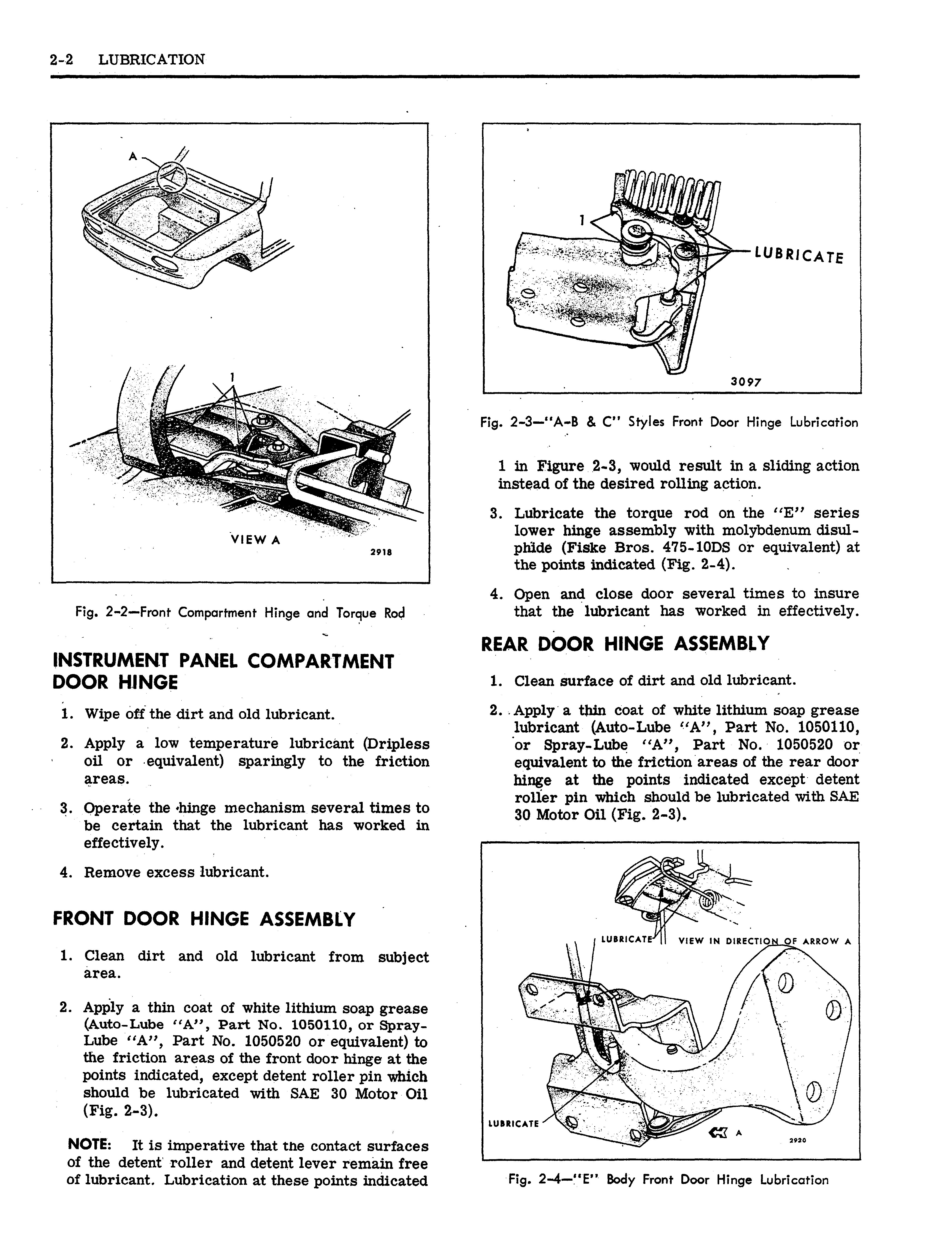
Lube "A", Part No. 1050520 or equivalent) to the friction areas of the front door hinge at the points indicated, except detent roller pin which should be lubricated with SAE 30 Motor Oil (Fig. 2-3).
NOTE: It is imperative that tne contact surfaces of the detent roller and detent lever remain free of lubricant. Lubrication at these points indicated
Fig. 2-3—"A-B & C" Styles Front Door Hinge Lubrication
1 in Figure 2-3, would result in a sliding action instead of the desired rolling action. 3. Lubricate the torque rod on the "E" series lower hinge assembly with molybdenum disulphide (Fiske Bros. 475-10DS or equivalent) at the points indicated (Fig. 2-4). 4. Open and close door several times to insure that the lubricant has worked in effectively.
REAR DOOR HINGE ASSEMBLY
1. Clean surface of dirt and old lubricant.
2. Apply a thin coat of white lithium soap grease lubricant (Auto-Lube "A", Part No. 1050110, or Spray-Lube "A", Part No. 1050520 or equivalent to the friction areas of the rear door hinge at the points indicated except detent roller pin which should be lubricated with SAE 30 Motor Oil (Fig. 2-3).
i LUBRICATE"^ 1 ! VIEW IN DIRECTIONt_OF ARROW A
LUBRICATE' / \|
•-— g l
2920
Fig. 2-5—Rear Door Hinge Lubrication
NOTE: It is imperative that the contact surfaces of the detent roller and detent lever remain free of lubricant. Lubrication at these points indicated 1 in Figure 2-5, would result in a sliding action instead of the desired rolling action.
3. Open and close door several times to insure that the lubricant has worked in effectively.

DOOR LOCK FORK BOLT
1. Clean the fork bolt surface.
2. Apply a thin coat of grease stick lubricant (Doorease or equivalent) to the areas indicated (Fig. 2-6).
3. Operate the lock mechanism several times.
DOOR JAMB SWITCH
1. Wipe off dirt.
2. Apply a thin coat of white lithium soap grease (Auto-Lube "A", Part No. 1050110, or Spray
Lube "A", Part No. 1050520 or equivalent) to the circumference and end surface of the switch plunger.
3. Operate the plunger several times to insure that the lubricant has been worked in effectively.
4. Remove excess lubricant.
DOOR LOCKING MECHANISM AND LOCK PARTS
1. Apply white lithium soap grease lubricant (Fiske Bros. Lo-Temp. Lubriplate #777 or equivalent) to the pivot points, ends of connecting rods, and other movable parts of the lock.
Fig. 2-6—Door Lock Fork Bolt Lubrication
2. Actuate the lock mechanism to insure smooth operation.
DOOR WINDOW REGULATOR AND CAMS O N STYLES WITH DOOR UPPER FRAMES 1. Applying a thin coat of white lithium soap grease (Fiske Bros. Lo-Temp. Lubriplate #777 equivalent) cover the entire length of the lower sash channel cam and inner panel cam as shown in Section "A-A", Figure 2-7.
LUBRICATE
SECTION A-A
2. Lubricate all connecting rod pivot points with
Auto-Lube "A", Part No. 1050110 or Spray
Lube "A", Part No. 1050520 or equivalent, at the points indicated in Figure 2-7.
3. Apply a thin coat of Auto-Lube "A", Part No. 1050110 or Spray-Lube "A", Part.No. 1050520 or equivalent, to the teeth of the sector gear and the pivot point of the balance arm and lift arm as indicated at points 1 in Figure 2-7.
4. Operate the glass, remote control, and lock to assure smooth operation.
NOTE: Rear door lubrication is similar.
DOOR WINDOW REGULATOR CAMS AND GUIDES ON STYLES WITHOUT UPPER FRAMES
1. Applying a thin coat of white lithium soap grease (Fiske Bros. Lo-Temp. Lubriplate #777 or equivalent), cover the entire length of the front guide, rear guide, the lower sash channel cam, and the inner panel cam as shown in the cross section "A-A", Figure 2-8.
2. Lubricate all connecting rod pivots points with
Auto-Lube "A", Part No. 1050110 or Spray
Lube "A", Part No. 1050520 or equivalent at the points indicated 1 in Figure 2-8.
3. Apply a thin coat of Auto-Lube "A", Part No. 1050110 or Spray-Lube "A", Part No. 1050520 or equivalent to the teeth of the sector gear and the pivot point of the balance arm and lift arm as indicated at points 2 in Figure 2-8.
4. Operate the window," remote control, and lock to assure smooth operation.

NOTE: Front door lubrication is similar.
n
LUBRICATE
Ul 292 4 SECTION A-A
REAR QUARTER WINDOW REGULATOR CAMS AND GUIDES
1. Apply a thin coat of white lithium soap grease lubricant (Fiske Bros. Lo-Temp. Lubriplate #777 or equivalent) to the friction areas indicated (Figs. 2-9 & 2-10).
2. Cover the entire length of the inner surface of all guides with Fiske Bros. Lo-Temp. Lubriplate #777 or equivalent as shown in the cross sections (Fig. 2-9 & 2-10).
3. Operate glass to insure smooth operation.
TAILGATE LOCK FORK BOLT
(Right and Left) —(Station Wagon Styles with Dual Acting Tailgate) 1. With tailgate in gate position, clean surface of right and left fork bolt.
2. Apply a thin coat of grease stick lubricant (Doorease or equivalent) to the areas indicated by Point 1, Figure 2-11 (Right Side Shown, and Figure 2-12 Left Side Similar).

3. Open and close tailgate (in gate position) several times.
LUBRICATE FULL LENGTH OFGUIDEWHICH CONTACTS ROLLERS
LUBRICATE
3099
SECTION B-B LUBRICATE SECTION A-A
3100
Fig. 2-10—"E" Styles - Quarter Window Regulator Lubrication
TAIL GATE LOCK STRIKER
(Station Wagon with Conventional Tailgate)
1. Wipe off dirt and old lubricant. 2. Apply a thin coat of grease stick lubricant (Doorease or equivalent) to the contact surfaces of the striker teeth (Fig. 2-13). 3. Open and close tail gate several times. 4. Remove excess lubricant.
CLICK HERE TO DOWNLOAD THE COMPLETE MANUAL
• Thank you very much for reading the preview of the manual . • You can download the complete manual from: www.heydownloads.com by clicking the link below

• Please note: If there is no response to
CLICKING the link, please download this PDF first and then click on it.
CLICK HERE TO DOWNLOAD THE COMPLETE MANUAL
