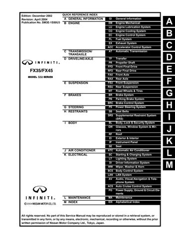
Edition: December 2002
Revision: April 2004
Publication No. SM3E-1S50U3
All rights reserved. No part of this Service Manual may be reproduced or stored in a retrieval system, or transmitted in any form, or by any means, electronic, mechanical, recording or otherwise, without the prior written permission of Nissan Motor Company Ltd., Tokyo, Japan.
A B C D E F G H I J K M L QUICK REFERENCE INDEX A GENERAL INFORMATION GI General Information B ENGINE EM Engine Mechanical LU Engine Lubrication System CO Engine Cooling System EC Engine Control System FL Fuel System EX Exhaust System ACC Accelerator Control System C TRANSMISSION/ TRANSAXLE AT Automatic Transmission D DRIVELINE/AXLE TF Transfer PR Propeller Shaft FFD Front Final Drive RFD Rear Final Drive FAX Front Axle RAX Rear Axle E SUSPENSION FSU Front Suspension RSU Rear Suspension WT Road Wheels & Tires F BRAKES BR Brake System PB Parking Brake System BRC Brake Control System G STEERING PS Power Steering System H RESTRAINTS SB Seat Belts SRS Supplemental Restraint System (SRS) I BODY BL Body, Lock & Security System GW Glasses, Window System & Mirrors RF Roof EI Exterior & Interior IP Instrument Panel SE Seat J AIR CONDITIONER ATC Automatic Air Conditioner K ELECTRICAL SC Starting & Charging System LT Lighting System DI Driver Information System WW Wiper, Washer & Horn BCS Body Control System LAN LAN System AV Audio, Visual,Navigation & Telephone System ACS Auto Cruise Control System PG Power Supply, Ground & Circuit Elements L MAINTENANCE MA Maintenance M INDEX IDX Alphabetical Index
• Thank you very much for reading the preview of the manual.
• You can download the complete manual from: www.heydownloads.com by clicking the link below
• Please note: If there is no response to CLICKING the link, please download this PDF first and then click on it.

CLICK HERE TO DOWNLOAD THE COMPLETE MANUAL
CLICK HERE TO DOWNLOAD THE COMPLETE MANUAL
This manual contains maintenance and repair procedure for the 2003 INFINITI FX35/FX45.
In order to assure your safety and the efficient functioning of the vehicle, this manual should be read thoroughly. It is especially important that the PRECAUTIONS in the GI section be completely understood before starting any repair task.
All information in this manual is based on the latest product information at the time of publication. The right is reserved to make changes in specifications and methods at any time without notice.
IMPORTANT SAFETY NOTICE
The proper performance of service is essential for both the safety of the technician and the efficient functioning of the vehicle. The service methods in this Service Manual are described in such a manner that the service may be performed safely and accurately. Service varies with the procedures used, the skills of the technician and the tools and parts available. Accordingly, anyone using service procedures, tools or parts which are not specifically recommended by NISSAN must first be completely satisfied that neither personal safety nor the vehicle’s safety will be jeopardized by the service method selected.
PLEASE HELP MAKE THIS SERVICE MANUAL BETTER!
Your comments are important to INFINITI and will help us to improve our Service Manuals
Use this form to report any issues or comments you may have regarding our Service Manuals
Please print this form and type or write your comments below. Mail or fax to:
Nissan North America, Inc.
Technical Service Information
39001 Sunrise Drive, P O Box 9200 Farmington Hills, MI USA 48331
FAX: (248) 488-3910
SERVICE MANUAL: Model: Year:
PUBLICATION NO. (Refer to Quick Reference Index ):
Please describe any Service Manual issues or problems in detail:
Page number(s) Note: Please include a copy of each page, marked with your comments
Are the trouble diagnosis procedures logical and easy to use? (circle your answer) YES NO
If no, what page number(s)? Note: Please include a copy of each page, marked with your comments
Please describe the issue or problem in detail:
Is the organization of the manual clear and easy to follow? (circle your answer) YES NO
Please comment:
What information should be included in INFINITI Service Manuals to better support you in servicing or repairing customer vehicles?
DATE: YOUR NAME: POSITION:
DEALER: DEALER NO : ADDRESS:
CITY: STATE/PROV /COUNTRY: ZIP/POSTAL CODE:
R I N F I N I T I
INCHTOMETRICCONVERSIONTABLE
(Rounded-offforautomotiveuse) inches mm inches mm .100 2.54 .610 15.49 .110 2.79 .620 15.75 .120 3.05 .630 16.00 .130 3.30 .640 16.26 .140 3.56 .650 16.51 .150 3.81 .660 16.76 .160 4.06 .670 17.02 .170 4.32 .680 17.27 .180 4.57 .690 17.53 .190 4.83 .700 17.78 .200 5.08 .710 18.03 .210 5.33 .720 18.29 .220 5.59 .730 18.54 .230 5.84 .740 18.80 .240 6.10 .750 19.05 .250 6.35 .760 19.30 .260 6.60 .770 19.56 .270 6.86 .780 19.81 .280 7.11 .790 20.07 .290 7.37 .800 20.32 .300 7.62 .810 20.57 .310 7.87 .820 20.83 .320 8.13 .830 21.08 .330 8.38 .840 21.34 .340 8.64 .850 21.59 .350 8.89 .860 21.84 .360 9.14 .870 22.10 .370 9.40 .880 22.35 .380 9.65 .890 22.61 .390 9.91 .900 22.86 .400 10.16 .910 23.11 .410 10.41 .920 23.37 .420 10.67 .930 23.62 .430 10.92 .940 23.88 .440 11.18 .950 24.13 .450 11.43 .960 24.38 .460 11.68 .970 24.64 .470 11.94 .980 24.89 .480 12.19 .990 25.15 .490 12.45 1.000 25.40 .500 12.70 2.000 50.80 .510 12.95 3.000 76.20 .520 13.21 4.000 101.60 .530 13.46 5.000 127.00 .540 13.72 6.000 152.40 .550 13.97 7.000 177.80 .560 14.22 8.000 203.20 .570 14.48 9.000 228.60 .580 14.73 10.000 254.00 .590 14.99 20.000 508.00 .600 15.24
(Rounded-offforautomotiveuse) mm inches mm inches 1 .0394 51 2.008 2 .079 52 2.047 3 .118 53 2.087 4 .157 54 2.126 5 .197 55 2.165 6 .236 56 2.205 7 .276 57 2.244 8 .315 58 2.283 9 .354 59 2.323 10 .394 60 2.362 11 .433 61 2.402 12 .472 62 2.441 13 .512 63 2.480 14 .551 64 2.520 15 .591 65 2.559 16 .630 66 2.598 17 .669 67 2.638 18 .709 68 2.677 19 .748 69 2.717 20 .787 70 2.756 21 .827 71 2.795 22 .866 72 2.835 23 .906 73 2.874 24 .945 74 2.913 25 .984 75 2.953 26 1.024 76 2.992 27 1.063 77 3.031 28 1.102 78 3.071 29 1.142 79 3.110 30 1.181 80 3.150 31 1.220 81 3.189 32 1.260 82 3.228 33 1.299 83 3.268 34 1.339 84 3.307 35 1.378 85 3.346 36 1.417 86 3.386 37 1.457 87 3.425 38 1.496 88 3.465 39 1.535 89 3.504 40 1.575 90 3.543 41 1.614 91 3.583 42 1.654 92 3.622 43 1.693 93 3.661 44 1.732 94 3.701 45 1.772 95 3.740 46 1.811 96 3.780 47 1.850 97 3.819 48 1.890 98 3.858 49 1.929 99 3.898 50 1.969 100 3.937
METRICTOINCHCONVERSIONTABLE
QUICK REFERENCE CHART FX35/FX45
ENGINE TUNE-UP DATA (VQ35DE)
QUICK REFERENCE CHART FX35/FX45 PFP:00000
ELS0003W Engine model VQ35DE Firing order 1-2-3-4-5-6 Idle speed A/T (In “P” or “N” position) rpm 650±50 Ignition timing (BTDC at idle speed) A/T (In “P” or “N” position) 15°± 5 ° CO% at idle 0.7 - 9.9 % and engine runs smoothly Drive Belt Deflection adjustment Unit: mm (in)Tension adjustment Unit: N (kg, lb) Used belt New belt Used belt New belt LimitAfter adjustmentLimit After adjustment Alternator and air conditioner compressor belt 7 (0.28) 4 - 5 (0.16 - 0.20) 3.5 - 4.5 (0.138 - 0.177) 294 (30, 66) 730 - 818 (74.5 - 83.5, 164 - 184) 838 - 926 (85.5 - 94.5, 188 - 208) Power steering oil pump belt 12 (0.47) 9 - 10 (0.35 - 0.39) 8 - 9 (0.31 - 0.35) 196 (20, 44) 348 - 436 (35.5 - 44.5, 78 - 98) 470 - 559 (48 - 57, 106 - 126) Applied pushing force98N (10kg, 22lb) — Radiater cap relief pressure kPa (kg/cm2 , psi) 78 - 98 (0.8 - 1.0, 11 - 14) Standard Limit59 (0.6, 9) Cooling system leakage testing pressure kPa (kg/cm2 , psi) 157(1.6, 23) Compression pressure kPa (kg/cm2 , psi)/rpm 1,275 (13.0, 185) /300 Standard Minimum981 (10.0, 142)/300 Spark plugStandard typePLFR5A - 11 Hot typePLFR4A - 11 Cold typePLFR6A - 11 2003
QUICK REFERENCE CHART FX35/FX45
ENGINE TUNE-UP DATA (VK45DE)
Tensions of drive beltsAuto adjustment by auto tensioner
FRONT WHEEL ALIGNMENT (Unladen* )
* : Fuel, engine coolant and engine oil full. Spare tire, jack, hand tools and mats in designated positions.
ELS0003X
Engine model VK45DE Firing order 1-8-7-3-6-5-4-2 Idle speed A/T (In “P” or “N” position)rpm 650±50 Ignition timing (BTDC at idle speed) 12 °±5°
CO% at idle 0.7 - 9.9 % and engine runs smoothly
78-98
Standard
157(1.6,
kPa (kg/cm2
Compression pressure 1,320 (13.5, 191) /300 Standard kPa (kg/cm2 , psi)/rpm Minimum 1,130 (11.5, 164)/300 Spark plugStandard typePLFR5A -
Hot typePLFR4A
Cold typePLFR6A - 11 CamberDegree minute (Decimal degree)Minimum– 1° 29′ ( – 1.48 ° ) Nominal– 0° 44′ ( – 0.73 ° ) Maximum 0 ° 01′ ( 0.02° ) Left and right difference45′ ( 0.75° ) or less CasterDegree minute (Decimal degree)Minimum3° 02′ ( 3.03° ) Nominal3° 47′ ( 3.78° ) Maximum4° 32′ ( 4.53° ) Left and right difference45′ ( 0.75° ) or less Kingpin inclinationDegree minute (Decimal degree)Minimum12° 20′ ( 12.33° ) Nominal13° 05′ ( 13.08° ) Maximum13° 50′ ( 13.83° ) Total toe-inDistance (A – B)Minimum0.6 mm ( 0.024 in ) Nominal1.6 mm ( 0.063 in ) Maximum2.6 mm ( 0.102 in ) Angle
Degree minute (Degree) Minimum–Nominal6′ ( 0.1° ) Maximum–Wheel turning angle (Full turn)InsideMInimum32 ° 00′ ( 32.0 ° ) Degree minute (Decimal degree)Nominal35 ° 00′ ( 35.0 ° ) Maximum36 ° 00′ ( 36.0 ° ) Outside Nominal30 ° 00′ ( 30.0 ° ) Degree minute (Decimal degree) 2003
Radiater cap relief pressure
(0.8-1.0 , 11-14 )
kPa (kg/cm2 , psi) Cooling system leakage testing pressure
23)
, psi)
11
- 11
(left plus right)
QUICK REFERENCE CHART FX35/FX45
REAR WHEEL ALIGNMENT (Unladen*)
* : Fuel, engine coolant and engine oil full. Spare tire, jack, hand tools and mats in designated positions.
* : Under force of 490 N( 50 kg, 110 lb ) with engine running.
ELS0003Y
BRAKE ELS0003Z
ELS00040 Camber Degree minute (Decimal degree) Minimum– 1° 18′ ( – 1.30° ) Nominal– 0 ° 48′ ( – 0.80° ) Maximum– 0 ° 18′ ( – 0.30° ) Total toe-in Distance ( A – B )Minimum2.4 mm ( 0.094 in ) Nominal4.7 mm ( 0.185 in ) Maximum7.0 mm ( 0.276 in ) Angle (left plus
) Degree minute (Degree) Minimum 0° 05 ′ ( 0.08° ) Nominal 0° 10 ′ ( 0.17° ) Maximum 0° 15 ′ ( 0.25° ) Front brakePad wear limit2.0 ( 0.079 ) Rotor repair limit26.0 mm ( 1.024 in ) Rear brakePad wear limit2.0 mm ( 0.079 in ) Rotor repair limit14.0 mm ( 0.551 in ) Pedal free height161.5 - 171.5 mm ( 6.358 - 6.752 in ) Pedal depressed height*90 mm ( 3.54 in ) UNIT LiterUS measure Fuel tank 9023 - 3/4 gal Coolant ( With reservoir tank ) VQ35DE8.69 - 1/8 qt VK45DE10.010 - 5/8 qt Engine(VQ35DE) Drain and refill With oil filter change4.75 qt Without oil filter change4.44 - 5/8 qt Dry engine (Overhaul)5.45 - 3/4 qt Engine(VK45DE) Drain and refill With oil filter change6.67qt Without oil filter change6.06 - 3/8 qt Dry engine (Overhaul)7.78 - 1/8 qt TransmissionA/T10.310 - 7/8 qt Transfer 1.252 - 5/8 pt Differential carrier Front0.651 - 3/8 pt Rear1.43 pt Power steering system1.01 - 1/8 qt Air conditioning system Compressor oil0.186.0 fl oz Refrigerant0.55 kg1.21 lb 2003
REFILL CAPACITIES
right
TEST VALUE AND TEST LIMIT (GST ONLY — NOT APPLICABLE TO CONSULT-II)
The following is the information specified in Mode 6 of SAE J1979. The test value is a parameter used to determine whether a system/circuit diagnostic test is “OK” or “NG” while being monitored by the ECM during self-diagnosis. The test limit is a reference value which is specified as the
maximum or minimum value and is compared with the test value being monitored. These data (test value and test limit) are specified by Test ID (TID) and Component ID (CID) and can be displayed on the GST screen.
SRT item
CATALYST
EVAP SYSTEM
Self-diagnostic test item
Three way catalyst function (Bank 1)
Three way catalyst function (Bank 2)
HO2S
HO2S HTR
Heated oxygen sensor 1 (Bank 1)
Heated oxygen sensor 1 (Bank 2)
Heated oxygen sensor 2 (Bank 1)
Heated oxygen sensor 2 (Bank 2)
Heated oxygen sensor 1 heater (Bank 1)
Heated oxygen sensor 1 heater (Bank 2)
Heated oxygen sensor 2 heater (Bank 1)
Heated oxygen sensor 2 heater (Bank 2)
Test limit Conversion DTC
Test value (GST display)
Attachment No.35 TID CID P0420 01H 01H Max. 1/128 P0420 02H 81H Min. 1 P0430 03H 02H Max. 1/128 P0430 04H 82H Min. 1 EVAP control system (Small leak) P0442 05H 03H Max. 1/128mm2 EVAP control system purge flow monitoring P0441 06H 83H Min. 20mV EVAP control system (Very small leak) P0456 07H 03H Max. 1/128mm2 P0133 09H 04H Max. 16ms P1143 0AH 84H Min. 10mV P1144 0BH 04H Max. 10mV P0132 0CH 04H Max. 10mV P0134 0DH 04H Max. 1s P0153 11H 05H Max. 16ms P1163 12H 85H Min. 10mV P1164 13H 05H Max. 10mV P0152 14H 05H Max. 10mV P0154 15H 05H Max. 1s P0139 19H 86H Min. 10mV/500ms P1147 1AH 86H Min. 10mV P1146 1BH 06H Max. 10mV P0138 1CH 06H Max. 10mV P0159 21H 87H Min. 10mV/500ms P1167 22H 87H Min. 10mV P1166 23H 07H Max. 10mV P0158 24H 07H Max. 10mV P0032 29H 08H Max. 20mV P0031 2AH 88H Min. 20mV P0052 2BH 09H Max. 20mV P0051 2CH 89H Min. 20mV P0038 2DH 0AH Max. 20mV P0037 2EH 8AH Min. 20mV P0058 2FH 0BH Max. 20mV P0057 30H 8BH Min. 20mV
ACC-1 ACCELERATOR
SYSTEM B ENGINE CONTENTS C D E F G H I J K L M SECTION ACC A ACC Revision; 2004 April 2003 FX ACCELERATOR CONTROL SYSTEM ACCELERATOR CONTROL SYSTEM ......................2 Removal and Installation ..........................................2 REMOVAL .............................................................2 INSTALLATION .....................................................2 INSPECTION AFTER INSTALLATION .................2
CONTROL
REMOVAL
1.Disconnect accelerator pedal position sensor harness connector.
2.Loosen nuts, and remove accelerator pedal assembly.
CAUTION:
● Do not disassemble the accelerator pedal assembly. Do not remove the accelerator pedal position sensor from the accelerator pedal assembly.
● Avoid impact from dropping etc. during handling.
● Be careful to keep the accelerator pedal assembly away from water.
INSTALLATION
Install in the reverse order of removal.
INSPECTION AFTER INSTALLATION
● Check that the accelerator pedal moves smoothly within the whole operation range.
● Check that the accelerator pedal securely returns to the original position.
● For the electrical inspection of the accelerator pedal position sensor, refer to EC-1247, "DTC P2138 APP SENSOR"
CAUTION:
When the harness connector of the accelerator pedal position sensor is disconnected, perform ″Accelerator Pedal Released Position Learning″. Refer to EC-703, "Accelerator Pedal Released Position Learning" .
ACC-2
Revision; 2004 April 2003 FX ACCELERATOR CONTROL SYSTEM PFP:18005 Removal and Installation ABS005ZA
ACCELERATOR CONTROL SYSTEM
SBIA0332E
1.Accelerator pedal assembly
• Thank you very much for reading the preview of the manual.
• You can download the complete manual from: www.heydownloads.com by clicking the link below
• Please note: If there is no response to CLICKING the link, please download this PDF first and then click on it.
CLICK HERE TO DOWNLOAD THE COMPLETE MANUAL
CLICK HERE TO DOWNLOAD THE COMPLETE MANUAL
AUTO CRUISE CONTROL SYSTEM
ACS-1
K ELECTRICAL CONTENTS C D E F G H I J L M SECTION ACS A B ACS Revision; 2004 April 2003 FX AUTO CRUISE CONTROL SYSTEM ASCD AUTOMATIC SPEED CONTROL DEVICE (ASCD).....3 Description ...............................................................3 ICC PRECAUTIONS ..........................................................4 Precautions for Supplemental Restraint System (SRS) “AIR BAG” and “SEAT BELT PRE-TENSIONER” ..................................................................4 Precautions for ICC System Service ........................4 Wiring Diagrams and Trouble Diagnosis ..................4 PREPARATION ...........................................................5 Special Service Tools ...............................................5 DESCRIPTION ............................................................6 Outline ......................................................................6 VEHICLE-TO-VEHICLE DISTANCE CONTROL MODE ...................................................................6 CONVENTIONAL (FIXED SPEED) CRUISE CONTROL MODE .................................................6 BRAKE ASSIST (WITH PREVIEW FUNCTION).....6 System Diagram .......................................................6 Components Description ..........................................7 CAN Communication ................................................7 CAN COMMUNICATION UNIT FOR 2WD MODEL .................................................................7 CAN COMMUNICATION UNIT FOR AWD MODELS ......................................................................11 Switch Operation ....................................................16 ICC System Display ...............................................16 ACTION TEST ..........................................................17 ICC System Running Test ......................................17 VEHICLE-TO-VEHICLE DISTANCE CONTROL MODE .................................................................17 CONVENTIONAL (FIXED SPEED) CRUISE CONTROL MODE ...............................................18 LASER BEAM AIMING ADJUSTMENT ...................20 Outline ....................................................................20 Preparation .............................................................20 Outline of Adjustment Procedure ...........................20 Setting the ICC Target Board ..................................20 ADJUSTING HEIGHT OF THE TARGET ............20 ADJUSTING THE RIGHT-LEFT POSITION OF THE TARGET ......................................................21 SETTING THE TARGET .....................................21 Aiming Adjustment ..................................................22 CHECK AFTER THE ADJUSTMENT ..................25 ELECTRICAL UNITS LOCATION ............................26 Component Parts and Harness Connector Location...26 WIRING DIAGRAM ...................................................27 Schematic ...............................................................27 Wiring Diagram — ICC — ......................................28 TERMINALS AND REFERENCE VALUE .................35 Terminals and Reference Value for ICC Unit ..........35 Terminals and Reference Value for ICC Sensor .....36 TROUBLE DIAGNOSIS — GENERAL DESCRIPTION ..........................................................................37 Work Flow ...............................................................37 CONSULT-II Function .............................................38 DESCRIPTION ....................................................38 CONSULT-II INSPECTION PROCEDURE ..........38 WORK SUPPORT ...............................................39 SELF-DIAGNOSTIC RESULTS ...........................39 DATA MONITOR .................................................40 ACTIVE TEST .....................................................41 Self-Diagnostic Function .........................................43 WITH CONSULT-II ..............................................43 WITHOUT CONSULT-II .......................................43 SELF-DIAGNOSIS BY ICC SYSTEM DISPLAY WILL NOT RUN. ..................................................44 TROUBLE DIAGNOSIS FOR SELF-DIAGNOSTIC ITEMS ........................................................................47 Diagnostic Trouble Code (DTC) Chart ...................47 DTC 11 CONTROL UNIT .......................................48 DTC 20 CAN COMM CIRCUIT ...............................48 DTC 31 POWER SUPPLY CIR 1, DTC 34 POWER SUPPLY CIR 2 .......................................................49 DTC 41 VHCL SPEED SE CIRC ............................49 DTC 43 VDC/TCS/ABS CIRC ................................50 DTC 45 BRAKE SW/STOP L SW ...........................50
Symptom 3: The ICC System Cannot Be Operated by the CANCEL Switch, ACCEL/RES Switch, or DISTANCE Switch.. ................................................68
Symptom 4: The ICC System Is Not Cancelled When the Gear Is in Other Than ‘D’
Symptom 6: Driving Force Is Hunting
Symptom 7: The ICC System Frequently Cannot Detect the Vehicle Ahead/The Detection Zone Is Short
Symptom 8: The System Does Not Detect the Vehicle
ACS-2 Revision; 2004 April 2003 FX
.............................52
PRESS
CIRCUIT ..............................53
......................54
CIRCUIT ...........................55
65 PRESSURE CONTROL ............................56 DTC 74 LASER BEAM OFF CNTR ........................56 DTC 90 STOP LAMP RLY FIX ...............................57 DTC 92 ECM CIRCUIT ...........................................61 DTC 96 NP RANGE ...............................................62 DTC 97 AT CIRCUIT ..............................................63 DTC 98 GEAR POSITION ......................................63 DTC 102 RADAR STAIN ........................................64 DTC 103 LASER SENSOR FAIL ............................65 DTC 104 LASER AIMING INCMP ..........................65 DTC 107 LASER COMM FAIL ................................65 DTC 109 LASER HIGH TEMP ...............................65 TROUBLE DIAGNOSIS FOR SYMPTOMS ..............66 Symptom Chart .......................................................66
1: ON/OFF Switch Does Not Switch ON*1 , ON/OFF Switch Does Not Switch OFF*2 ..............67
2: The ICC System Cannot Be Set (ON/ OFF Switch Turns On/Off). .....................................67
DTC 46 OPERATION SW CIRC
DTC 61
SEN
DTC 62 BOOSTER SOL/V CIRCUIT
DTC 63 RELEASE SW
DTC
Symptom
Symptom
......................69
........................69 Symptom 5: Chime Does Not Sound
.....................70
Ahead at
.......................................................70 ELECTRICAL COMPONENT INSPECTION .............72 ICC Steering Switch ................................................72 ICC Brake Switch and Stop Lamp Switch ...............72 Booster Solenoid .....................................................72 Release Switch .......................................................73 REMOVAL AND INSTALLATION ..............................74 ICC Unit ..................................................................74 ICC Sensor .............................................................74 ICC Steering Switch ................................................74
.......................................................................70
All
AUTOMATIC SPEED CONTROL DEVICE (ASCD)
[ASCD] AUTOMATIC SPEED CONTROL DEVICE (ASCD)
Description
Regarding the information for ASCD system, refer to EC-657, "AUTOMATIC SPEED CONTROL DEVICE (ASCD)" (VQ35DE), EC-1329, "AUTOMATIC SPEED CONTROL DEVICE (ASCD)" (VK45DE).
ACS-3 [ASCD] C D E F G H I J L M A B ACS Revision; 2004 April 2003 FX
PFP:18930
AKS007XN
Precautions for Supplemental Restraint System (SRS) “AIR BAG” and “SEAT BELT PRE-TENSIONER”
AKS007IE
The Supplemental Restraint System such as “AIR BAG” and “SEAT BELT PRE-TENSIONER”, used along with a front seat belt, helps to reduce the risk or severity of injury to the driver and front passenger for certain types of collision. This system includes seat belt switch inputs and dual stage front air bag modules. The SRS system uses the seat belt switches to determine the front air bag deployment, and may only deploy one front air bag, depending on the severity of a collision and whether the front occupants are belted or unbelted. Information necessary to service the system safely is included in the SRS and SB section of this Service Manual.
WARNING:
● To avoid rendering the SRS inoperative, which could increase the risk of personal injury or death in the event of a collision which would result in air bag inflation, all maintenance must be performed by an authorized NISSAN/INFINITI dealer.
● Improper maintenance, including incorrect removal and installation of the SRS, can lead to personal injury caused by unintentional activation of the system. For removal of Spiral Cable and Air Bag Module, see the SRS section.
● Do not use electrical test equipment on any circuit related to the SRS unless instructed to in this Service Manual. SRS wiring harnesses can be identified by yellow and/or orange harnesses or harness connectors.
Precautions for ICC System Service
● Do not look straight into the laser beam discharger when adjusting laser beam aiming.
AKS006Y8
● Turn the ON/OFF switch OFF in conditions similar to driving, suchlike Free rollers or Chassis dynamometer.
● Do not use the ICC sensor removing from vehicle, disassemble, or remodel the sensor.
● Erase DTC when replacing parts of ICC system, then check the operation of ICC system after adjusting laser beam aiming if necessary.
Wiring Diagrams and Trouble Diagnosis
When you read wiring diagrams, refer to the followings:
● Refer to GI-15, "How to Read Wiring Diagrams" in GI section
● Refer to PG-3, "POWER SUPPLY ROUTING CIRCUIT" for power distribution circuit in PG section
When you perform trouble diagnosis, refer to the followings:
● Refer to GI-11, "HOW TO FOLLOW TEST GROUPS IN TROUBLE DIAGNOSES" in GI section
● Refer to GI-27, "How to Perform Efficient Diagnosis for an Electrical Incident" in GI section
AKS006Y9
ACS-4 [ICC] PRECAUTIONS Revision; 2004 April 2003 FX [ICC] PRECAUTIONS PFP:00001
PREPARATION
Special Service Tools
The actual shapes of Kent-Moore tools may differ from those of special service tools illustrated here.
Tool number (Kent-Moore No.)
Tool name Description
KV99110100 (J-45718) ICC target board Laser beam aiming adjustment
PREPARATION ACS-5 [ICC] C D E F G H I J L M A B ACS Revision; 2004 April 2003 FX
PFP:00002
AKS006YA
PKIA0358J
DESCRIPTION
Outline
The Intelligent Cruise Control (ICC) system automatically maintains a selected distance from the vehicle ahead according to that vehicle's speed, or at the set speed, if the road ahead is clear.
The ICC function has two cruise control modes and brake assist (with preview function).
VEHICLE-TO-VEHICLE DISTANCE CONTROL MODE
Vehicle-to-vehicle distance control mode, the same speed as other vehicles can be maintained without the constant need to adjust the operating speed as with a normal cruise control system.
The system is intended to enhance the operation of the vehicle when following another vehicle in the same lane and direction.
If the distance sensor detects a slower moving vehicle ahead, the system will reduce speed so that the vehicle ahead can be followed at the selected distance.
The system automatically controls the throttle and applies the brakes (up to 25% of vehicle braking power) if necessary.
The detection range of the sensor is approximately 390 ft (120 m) ahead.
CONVENTIONAL (FIXED SPEED) CRUISE CONTROL MODE
Conventional (fixed speed) cruise control mode is cruising at preset speeds.
BRAKE ASSIST (WITH PREVIEW FUNCTION)
When the force applied to brake pedal exceeds a certain level, the Brake Assist is activated and generates a greater braking force than that of a conventional brake booster even with light pedal force.
When the Preview Function identifies the need to apply the sudden brake by sensing the vehicle ahead in the same lane and the distance and relative speed from it, it applies the brake pre-pressure before driver depress the brake pedal and improves brake response by reducing its free play.
Refer to Owner's Manual for Intelligent Cruise Control System operating instructions.
System Diagram
ACS-6 [ICC]
Revision; 2004 April 2003 FX
DESCRIPTION
PFP:00000
AKS006YB
AKS006YC SKIA5972E
Components Description AKS006YD
Component
ICC unit
Vehicleto-vehicle distance control mode
Conventional (fixed speed) cruise control mode
Brake assist (with preview brake)
Description
××× Operates throttle control actuator and brake booster based on that sensor signals and CAN communication data, then controls vehicle distance.
ICC sensor ×× Irradiate laser beam, and receives reflected laser beam to measure distance from preceding vehicle.
ECM
ABS actuator and electric unit (control unit)
Brake pressure sensor
Brake booster
×× Transmits throttle position signal and ICC steering switch signal to ICC unit.
××× Transmits wheel speed signal to ICC unit.
×× Detects fluid pressure in master cylinder.
×× Adjusts brake fluid pressure, based on command from ICC unit.
BCM × Transmit front wiper request signal to ICC unit.
TCM ×× Transmits gear position signal and output shaft revolution signal to ICC unit.
CAN Communication
CAN (Controller Area Network) is a serial communication line for real time application. It is an on-vehicle multiplex communication line with high data communication speed and excellent error detection ability. Many electric control units are equipped onto a vehicle, and each control unit shares information and links with other control units during operation (not independent). In CAN communication, control units are connected with 2 communication lines (CAN H line, CAN L line) allowing a high rate of information transmission with less wiring. Each control unit transmits/receives data but selectively reads required data only.
CAN COMMUNICATION UNIT FOR 2WD MODEL System
Diagram
DESCRIPTION ACS-7 [ICC] C D E F G H I J L M A B ACS Revision; 2004 April 2003 FX
AKS00815
SKIA6173E
• Thank you very much for reading the preview of the manual.
• You can download the complete manual from: www.heydownloads.com by clicking the link below
• Please note: If there is no response to CLICKING the link, please download this PDF first and then click on it.
CLICK HERE TO DOWNLOAD THE COMPLETE MANUAL
CLICK HERE TO DOWNLOAD THE COMPLETE MANUAL
DESCRIPTION
Input/output Signal Chart
SignalsECMTCM
Display control unit
Low tire pressure warning control unit
ICC unit
Intelligent Key unit BCM
Steeri ng angle sensor
Unified meter and A/C amp.
ICC sensor
T: Transmit R: Receive
ABS actuator and electric unit (control unit)
Engine speed signalTRRRRR
Engine status signalTR
Engine coolant temperature signal TRRR
A/T self-diagnosis signalRT
Accelerator pedal position signal TRRR
Closed throttle position signal TR R
Wide open throttle position signal TR
Battery voltage signalTR
Driver seat control unit
IPDM E/R
Key switch signalTR
Ignition switch signalTRR
P range signalTRRR
Stop lamp switch signalRT
ABS operation signalRRT
TCS operation signalRRT
VDC operation signalRRT
Fuel consumption monitor signal TRR
Input shaft revolution signal RTR
ACS-8 [ICC]
Revision; 2004 April 2003 FX
A/C compressor request signal T R A/C relay status signalR T A/C compressor feedback signal TR Blower fan motor switch signal RT A/C control signal TR RT Cooling fan speed signalR T Position light request signal RTRR Low beam request signalTR Low beam status signalR T
Output shaft revolution signal RTR A/C switch signalRT
SignalsECMTCM
High beam request signal
High beam status signalR
Front fog light request signal
Day time running light request signal
Turn LED burnout status signal
Vehicle speed signal
Sleep wake up signal
Low tire pressure warning control unit
ICC unit
Intelligent Key unit BCM
Steeri ng angle sensor
Unified meter and A/C amp.
ICC sensor
Driver seat control unit
ABS actuator and electric unit (control unit) E/R
IPDM
Door switch signalRRTRRR
Turn indicator signalTR
Key fob ID signalTR
Key fob door unlock signal
Oil pressure switch signal
Buzzer output signal
Fuel level sensor signalRT
Fuel level low warning signal
ICC operation signalRT
Front wiper request signal
Front wiper stop position signal
Rear window defogger switch signal TR
Rear window defogger control signal RRRT
Hood switch signalRT
Theft warning horn request signal TR
Horn chirp signalTR
Steering angle sensor signal TR
Tire pressure signalTR
DESCRIPTION ACS-9 [ICC] C D E F G H I J L M A B ACS Revision; 2004 April 2003 FX
TRR
T
TR
TR
RT
RRT RRRRRRTRR
TRRR TR
TR
RT TR
TR TR TR
RT
RTR
RT
Display control unit
SignalsECMTCM
Low tire pressure warning control unit
Tire pressure data signalRT
ICC unit
Intelligent Key unit BCM
Steeri ng angle sensor
Unified meter and A/C amp.
ICC sensor
Driver seat control unit
IPDM
ABS actuator and electric unit (control unit) E/R
ABS warning lamp signalRRT
VDC OFF indicator lamp signal RRT
SLIP indicator lamp signal
Brake warning lamp signal RT
System setting signalTRR
Distance to empty signalRT
Hand brake switch signalRT
Door lock/unlock request signal TR
Door lock/unlock status signal RT
Starter permission signalTR
Back door open request signal
Power window open request signal
Alarm request signalTR
Key warning signalTR
ICC sensor signalRT
ICC warning lamp signalTR
ICC system display signal
Current gear position signal TRR
Steering switch signalTR
ASCD operation signalTR
ASCD OD cancel request TR
ICC OD cancel requestRRT
A/T CHECK indicator lamp signal
A/T position indicator lamp signal
ACS-10 [ICC]
Revision; 2004 April 2003 FX
DESCRIPTION
RT
TR
TR
TR
TR
TR
RT
A/T shift schedule change demand signal R T Manual mode signalRT Not manual mode signalRT Manual mode shift up signal
Display control unit
Display control unit
Low tire pressure warning control unit
ICC unit
Intelligent Key unit BCM
Steeri ng angle sensor
Unified meter and A/C amp.
Manual mode shift down signal RT
Manual mode indicator signal TRR
Ignition knob switch signal TR
CAN COMMUNICATION UNIT FOR AWD MODELS
System Diagram
ICC sensor
ABS actuator and electric unit (control unit)
Driver seat control unit SKIA6176E
IPDM E/R
DESCRIPTION ACS-11 [ICC] C D E F G H I J L M A B ACS Revision; 2004 April 2003 FX
SignalsECMTCM
• Thank you very much for reading the preview of the manual.
• You can download the complete manual from: www.heydownloads.com by clicking the link below
• Please note: If there is no response to CLICKING the link, please download this PDF first and then click on it.
CLICK HERE TO DOWNLOAD THE COMPLETE MANUAL
CLICK HERE TO DOWNLOAD THE COMPLETE MANUAL