
Technical Manual
• Thank you very much for reading the preview of the manual.
• You can download the complete manual from: www.heydownloads.com by clicking the link below
• Please note: If there is no response to CLICKING the link, please download this PDF first and then click on it.

192-M
TABLE OF CONTENTS
General Information
Engineering Data
Lubrication
Air Systems and Components
Mechanical Adjustments Operation
Welding Instruction
Centralized Lubrication System Installation of Open & Semi-Enclosed Gear Set Instruction for Shrink Fit Pinions Wire Care
Strand Handling
DUE TO THE DANGERS INHERENT IN THE OPERATION OF ANY HIGH VOLTAGE ELECTRICAL EQUIPMENT, A SAFE GROUNDING SYSTEM SHOULD BE USED. SUCH SYSTEM SHOULD INCLUDE GROUND CONDUCTORS IN THE CABLE, A NEUTRAL GROUNDING RESISTOR AND RELATED RELAYS AND SWITCHGEAR. A GROUND CONTINUITY CHECK SYSTEM IS ALSO RECOMMENDED.
This manual has been prepared for the standard production machine. Any deviation due to advanced engineering design, optional equipment or the particular requirements of this machine may not be covered.
Additional information that is required will be furnished as soon as such information is available.

GENERAL INFORMATION
INTRODUCTION
This manual is provided for the guidance of all persons who operate, lubricate, adjust or maintain this machine. The information was prepared with the purpose in mind of furnishing accurately and concisely all the data necessary to the operation and servicing of this machine.
All information, measurements, and specifications herein are in accord with the Marion Power Shovel Engineering Department and should be strictly adhered to in all work on this machine.
PARTS BOOK
THIS MANUAL IS NOT A PARTS BOOK AND SHOULD NOT BE USED IN ORDERING PARTS.
You have been furnished detailed Parts Books which list all parts by group numbers with items and part numbers for your specific machine.
Read carefully the instructions in the front of the Parts Book for ordering parts.
SERIAL NUMBER OF MAC HINE
Be sure that the serial number of the machine is given in any letters, telegrams, orders or other communications. Records for each individual machine are filed by serial number and if this number is available, the design and original equipment can be quickly and accurately checked.
RIGHT AND LEFT HAND PARTS
On the upper frame, right hand (R. H. ) and left hand (L. H. ) correspond to the operator I s right and left hands when he is facing the dipper while at the operator's controls. Page 3 Section 1 192-M
ORDERING PARTS
The Parts Book covering this machine gives complete information on how to order parts. Order carefully so that the right parts in the right quantities can be furnished. Wrong parts, ordered by mistake, which are returned to the company are subject to a rehandling charge.
FURTHER INFORMATION
If further information is required which is not found in the Manual or in the Parts Books, communicate with the Marion Power Shovel Company, Inc., at Marion, Ohio.
CHARGE FOR SERVICE, LABOR, ETC.
No charges for service or labor are accepted unless the work has been previously authorized by the company in writing.
STANDARD WARRANTY
Marion Power Shovel Company, Inc. guarantees the equipment manufactured by it to be free from defects in material and workmanship under normal use and service, its obligation under this warranty being limited to making good at its factory any part or parts thereof manufactured by it which shall, within six (6) months after delivery to Buyer, be returned to it, with transportation charges prepaid, and which its examination shall disclose to its satisfaction to have been thus defective, this warranty being expressly in lieu of all warranties, express or implied, and of all other obligations or liabilities on Marion Power Shovel Company's part.
Marion Power Shovel Company, Inc. shalL not be held responsible or liable in any event for special or consequential damages, arising from any cause whatsoever, and Buyer agrees to indemnify and save Marion Power Shovel Company, Inc. harmless therefrom.
Marion Power Shovel Company, Inc. makes no guaranty or warranty, express or implied, as to adequancy, fitness, quality, or performance of any machinery, equipment, apparatus or accessories not manufactured at its own factory.
which are subject only to such guaranty as may be made by the respective manufacturers thereof.
The company reserves the right to improve or change the design of itspr:oductsand specifications thereof and the company shall incur no liability thereby or any obligations to install such improvements on products previously sold.
SAFETY PRECAUTIONS
The usefulness of this machine depends entirely on the man at the controls. The operator is its brain. He must think safety and work safely.
Neatness and safety go hand in hand. Good housekeeping habits should be developed.
1. Keep the floor clean and free from oil and grease.
2. Keep the walkways clean, clear and free from obstructions.
3. Prevent the accumulation of grease and oil around bearings and gears. Grease and oil collect and hold grit and dirt which work into finely machined parts.
4. A clean machine is easier to operate - easier to inspect - easier to service.
5. Keep hands and clothing away from moving parts.
6. Replace guards, inspection plates, access covers, etc., promptly after reason for removal is accomplished.
Strip mining equipment is subject to tremendous stresses and impact loads. These stresses are thoroughly studied and considered in the design and building of Marion equipment.
This machine is built with an ample reserve of power and strength and is well fitted to meet the demands of its task.
However, the Marion engineers cannot foresee the conditions imposed by abuse, mismanagement and neglect. These
factors are more damaging to any piece of equipment than years of continuous operation and normal wear.
Care, sound judgment and reason are an economic necessity in the operation of power equipment. DO
1. Carefully read this Manual and Parts Book.
2. Lubricate regularly. Establish a systematic procedure and stick to it.
3. When lubricating, check all bolts, nuts, locknuts and cotter pins.
4. Keep loose objects in tool box or in suitable enclosure or cabinet.
5. Close cab windows when AC is operating.
6. Always replace guards.
7. Keep house doors closed when filter fans are operating.
8. Always watch your clearance when swinging.
DON'T
1. Service or lubricate parts that are moving.
2. Leave the load suspended in air.
3. Use toxic or inflammable cleaning solvents.
4. Board the machine while in operation.
5. Operate with insufficient air pressure.
6. Swing with dipper in the bank.
7. Shift from propel to dig without making sure propel brake is set.
DON'T APPLY SWING BRAKES WHILE MACHINE IS ROTATING, EXCEPT IN EMERGENCY.
 1t92-M

The information provided in this section should be considered general in nature. It includes established procedures recommended by Marion engineers which may or may not wholly apply to your machine. Those applicable are by reference.
ENGINEERING DATA
Marion machines have been designed and built to rigid specifications in accordance to acceptable standards of the industry.
For the proper maintenance of this machine, we furnish the following information. This information is confidential and is to be used only in the interest of Marion Power Shovel Company.
JOURNAL BUSHINGS
Bronze sleeve bushings are assembled in the bearing bosses with a light press fit.
THRUST WASHERS
Each thrust washer is secured with a minimum of four dowels, to restrict rotation. Dowel material is to be softer than the washer material.
BUSIDNG OR JOURNAL
When the running clearance exceeds three times the figure shown in the table, the bushing is worn out and should be replaced.
TO REPLACE JOURNAL BUSIDNG
Disassemble shaft and machinery from bushing to be replaced. Remove bushing by slitting the bushing with air chisel or use air arc cutting torch. Be careful not to cut or score the bearing boss.
Clean the boss thoroughly and remove all burrs.
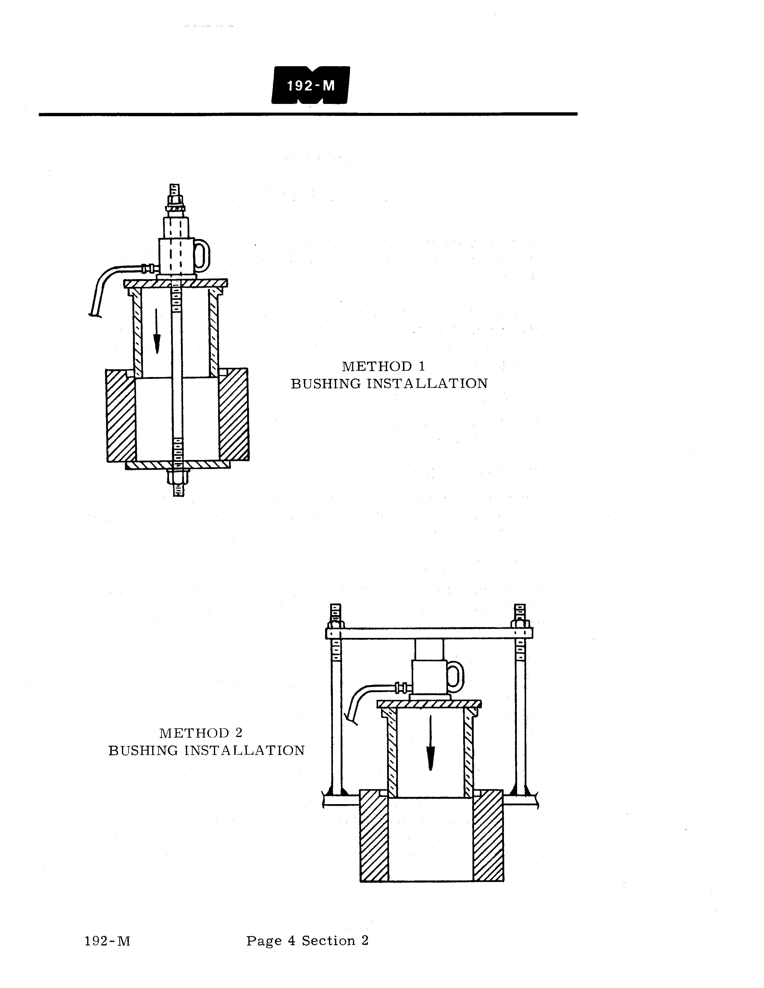
Break the corner of the replacement bushing and lightly coat the outside of the bushing with white lead. If a press is not available the bushing can be installed with the help of a portable, hydraulic power pak as shown in sketches.
METHOD 1 BUSHING INSTALLATION
METHOD 2 BUSHING INSTALLATION
INST ALLATION OF ANTI - FRICTION BEARINGS ON SHAFTS
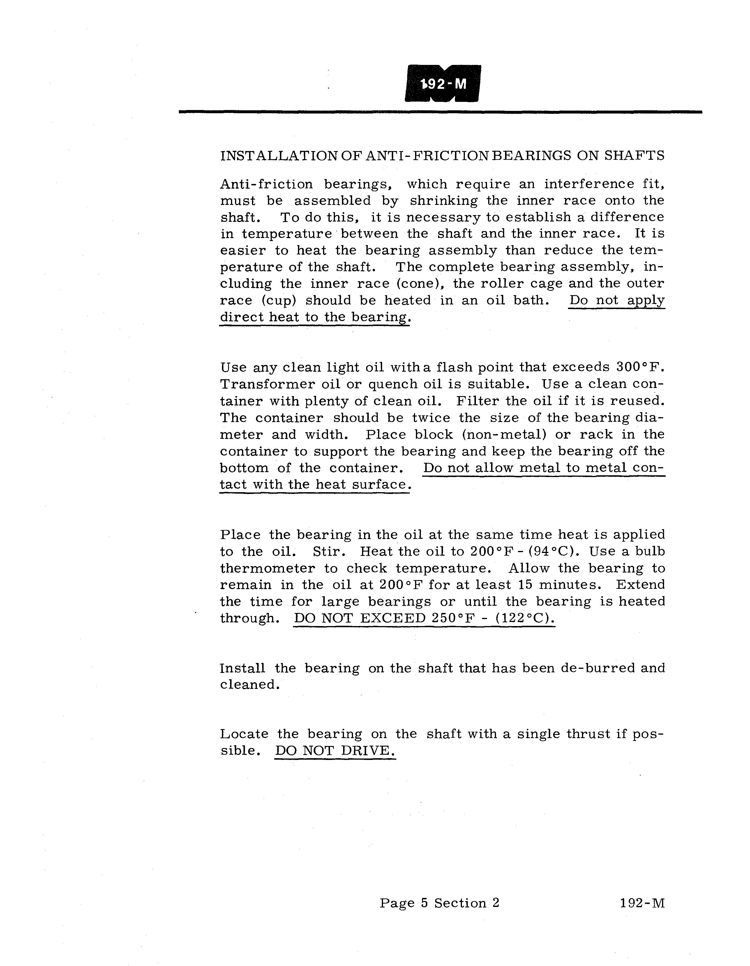
Anti-friction bearings, which require an interference fit, must be assembled by shrinking the inner race onto the shaft. To do this, it is necessary to establish a difference in temperature· between the shaft and the inner race. It is easier to heat the bearing assembly than reduce the temperature of the shaft. The complete bearing assembly, including the inner race (cone), the roller cage and the outer race (cup) should be heated in an oil bath. Do not apply direct heat to the bearing.
Use any clean light oil with a flash point that exceeds 300°F. Transformer oil or quench oil is suitable. Use a clean container with plenty of clean oil. Filter the oil if it is reused. The container should be twice the size of the bearing diameter and width. Place block (non-metal) or rack in the container to support the bearing and keep the bearing off the bottom of the container. Do not allow metal to metal contact with the heat surface.
Place the bearing in the oil at the same time heat is applied to the oil. Stir. Heat the oil to 200°F- (94°C). Use a bulb thermometer to check temperature. Allow the bearing to remain in the oil at 200°F for at least 15 minutes. Extend the time for large bearings or until the bearing is heated through. DO NOT EXCEED 250°F - (l22°C).
Install the bearing on the shaft that has been de- burred and cleaned.
Locate the bearing on the shaft with a single thrust if possible. DO NOT DRIVE.
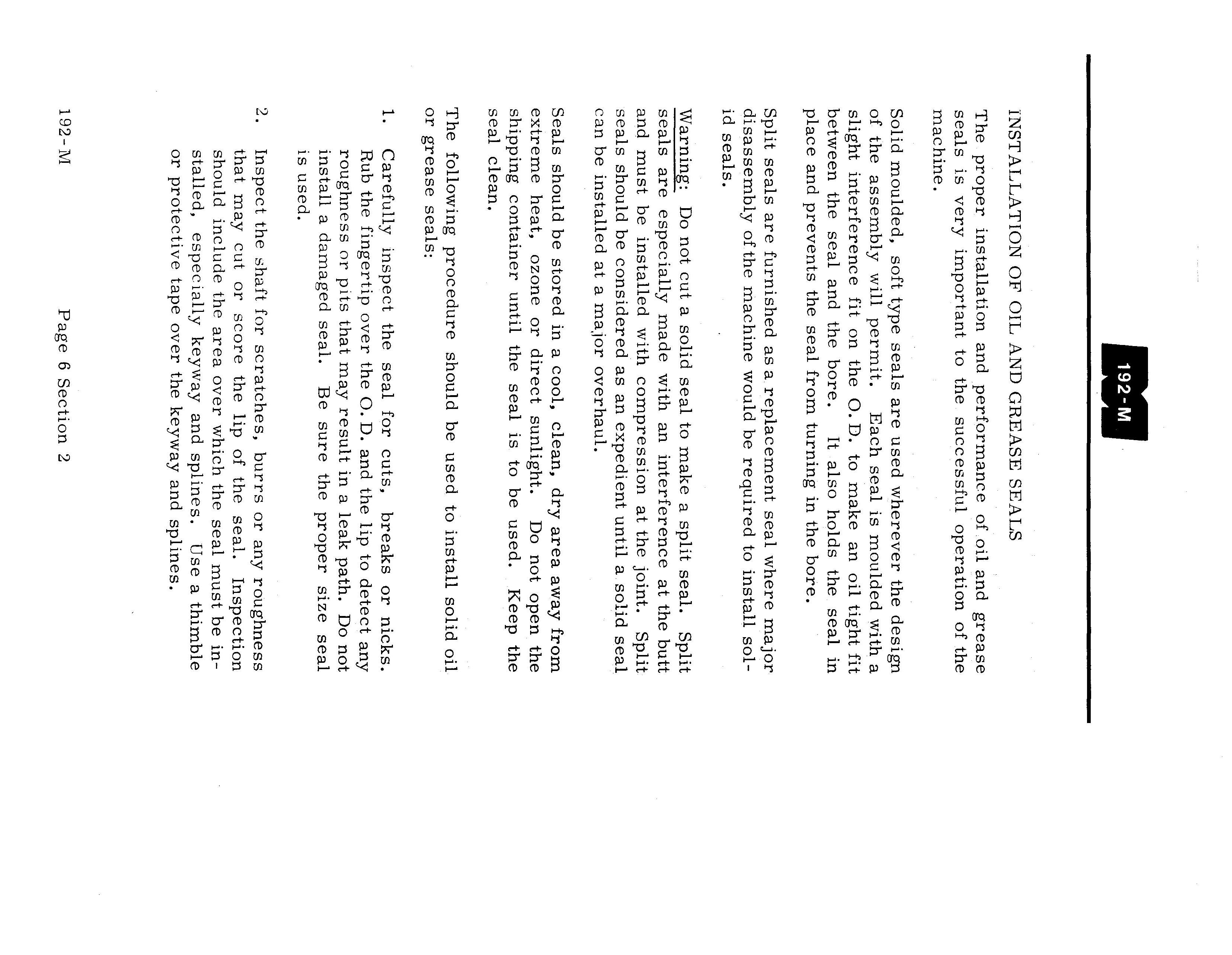
INST ALLATION OF OIL AND GREASE SEALS
The proper installation and performance of oil and grease seals is very important to the successful operation of the machine. Solid moulded, soft type seals are used wherever the design of the assembly will permit.
Each seal is moulded with a slight interference fit on the O. D. to make an oil tight fit between the seal and the bore.
It also holds the seal in place and prevents the seal from turning in the bore.
Split seals are furnished as a replacement seal where major disassembly of the machine would be required to install solid seals.
Warning: Do not cut a solid seal to make a split seal. Split seals are especially made with an interference at the butt and must be installed with compression at the joint. Split seals should be considered as an expedient until a solid seal can be installed at a major overhaul. Seals should be stored in a cool, clean, dry area away from extreme heat, ozone or direct sunlight.
Do not open the shipping container until the seal is to be used.
Keep the seal clean.
The following procedure should be used to install solid oil or grease seals:
Carefully inspect the seal for cuts, breaks or nicks. Rub the fingertip over the O. D. and the lip to detect any roughness or pits that may result in a leak path. Do not install a damaged seal.
Be sure the proper size seal is used.
1.
Inspect the shaft for scratches, burrs or any roughness that may cut or score the lip of the seal. Inspection should include the area over which the seal must be installed, especially keyway and splines. 192-M
Use a thimble or protective tape over the keyway and splines. Page 6 Section 2
3. Inspect the bore for burrs or any roughness that may cut or scrape the O. D. of the seal when the seal is pressed into place. The bore and the shaft should have a 1/16" chamfer. If not, carefully break the corner of the seal.
4. Determine the proper position of the lip. Should the seal be used to retain fluid or grease in a bearing or case? Or should the seal exclude contaminates from the bearing or case? Position the seal with the lip turned toward the inside to retain grease or oil in the housing or toward the outside to keep out contaminates such as dust or dirt.
5. Lubricate the seal with light grease or oil on all surfaces of the seal, particularly the O. D. and the lip. Lubricate the shaft and the interior of the bore with a light coat of grease or oil.
6. Very carefully install the seal on the shaft. Be sure the lip is in the proper position and be sure the garter spring is in the slot. Move the seal from the end of the shaft to the bore with a spiral rotating motion.
7. Align the seal in the bore and tap lightly with a hammer and wood block. Alternate from side to side and around until the seal is firmly seated in the bore. No retainer plate is required.
Two seals may be installed in a bore, back-to- back, to retain grease or oil and at the same time exclude contaminates from the bearing. In this case fill the space between the seals with MPG grease.
SPLIT SEALS
Split seals are installed in much the same manner.
1. First remove the garter spring and separate at the hook and eye.
7
• Thank you very much for reading the preview of the manual.
• You can download the complete manual from: www.heydownloads.com by clicking the link below
• Please note: If there is no response to CLICKING the link, please download this PDF first and then click on it.