AForeword
BSafety
CPreventive maintenance
0Complete machine
1Engine
2Transmission
3Driveline/axle
4Brakes
5Steering
6Suspension
7Load handling
8Control system
9Frame, body, cab and accessories
10Common hydraulics
11Common electrics
12Common pneumatics
DError codes
ESchematics
FTechnical data
• Thank you very much for reading the preview of the manual.
• You can download the complete manual from: www.heydownloads.com by clicking the link below
• Please note: If there is no response to CLICKING the link, please download this PDF first and then click on it.

Foreword
About the Workshop Manual
General
Thank you for choosing Kalmar Industries as your machine supplier. We hope that we'll meet your expectations.
Conditions
The instructions are based on the use of generally available standard tools. All lifting devices, for example, slings, straps, ratchet blocks, etc., must meet governing national standards and regulations for lifting devices.
Kalmar Industries will not accept any responsibility for modifications performed without permission from Kalmar Industries or if other lifting devices, tools or work methods are used other than those described in this manual.
Storage
NOTE
The Maintenance Manual should be accessible to the service personnel.
About the machine version
The information in this publication corresponds to the machine's design and appearance at the time of delivery from Kalmar Industries. Due to customizations, there may be variations and/or deviations. Kalmar Industries reserves the right to modify specifications and equipment without prior notice. All information and data in this manual are valid at the time of publication.
Copyright
Kalmar Industries AB
Duplication of the content in this manual, in whole or in part, is strictly prohibited without written permission from Kalmar Industries AB. Duplication by any means such as copying, printing, etc., is prohibited.
Workshop manual DRF 400–450
page
Reading instructions
Warning information
DANGER
Situation that may result in serious personal injury, possible death, if the instruction is not followed.
WARNING
Situation that may result in serious personal injury if the instruction is not followed.
CAUTION
Situation that may result in damage to the product if the instruction is not followed.
Warnings inform on potential dangers which can, if the warnings are not heeded, result in personal injury or product damage. page
Important information
Important information marked with NOTE facilitates the work process, operation/handling or increases understanding of the information.
NOTE
Information that is important without being safety related. page
Read operator's manual
The symbol to the left is used in certain cases on the machine and refers to important information in the operator’s manual. page
Read the operator's manual
Read maintenance manual
The symbol to the left is used in certain cases on the machine and refers to important information in the maintenance manual.
Read the maintenance manual
Workshop manual DRF 400–450
A Foreword
Workshop manual contents
The Workshop manual contains information for corrective maintenance (component replacement) and is a supplement to the maintenance manual. Supplier documentation for engine, transmission, and drive axle belongs to the Workshop manual. In some cases, the Workshop manual refers to the supplier documentation to avoid doubled information. Methods for preventive maintenance and certain checks are found in the maintenance manual, no reference are made to these. Use the function groups to find the information in the maintenance manual.
The workshop manual is divided into the following sections.
General information about the workshop manual's purpose, contents and reading instructions as well as survey for feedback of views and any inaccuracies.
B Safety Keep in mind for your safety.
C Preventive maintenance Reference to maintenance manual: Preventive maintenance. 0
Technical description, comprehensive function descriptions and a description of the function of components included in the machine, divided into function groups.
Under each sub-function there is a description of the components that are used for respective function. Therefore common components are described in several places, but generally under the first function that uses the component.
Together with the general description there is a detailed description of that which is unique for that specific sub-function. For the next sub-function that uses the same component, only the unique for the new function is described.
Work instructions for corrective maintenance (replacement of components).
Error code information and instructions for reading error code information.
Wiring diagrams and hydraulic diagrams as well as list of electric components.
Technical data, conversion tables, information for conversion of units.
General terminology and abbreviations, explanations of terms and abbreviations that may appear in the sections, index register for headings in the manual.
Function group structure
The information in the manual is divided in a structure of functions at different levels, based on the machine's design and use, called function groups.
The upper level (called main group) determines area, e.g., group 7 Load handling. The second level (called two-digit) determines function, e.g., 7.2 Lift and lower. The third and fourth levels are used to break down functions in smaller parts (components).
The function groups' structure for main group and two-digit group level are common for all machines from Kalmar Industries, e.g., 4.3 Servo brake system. Machine-unique adaptations of functions are done at the third and fourth group level, e.g., 4.3.9 Wheel brake and 4.3.9.1 Disc pack. This means that certain function groups (headings) will be left out in the documentation for certain machines since the machine is missing that specific function or component. In turn, this means that there may be skips in the function groups' numbering (e.g., the threedigit heading level 4.8.7 Oil cooler may be included for some machines, but is missing for others).
The function groups are intended to be used as search terms to find different types of information between different sections and manuals. The information in a function group is divided in smaller sections according to the type of content, e.g., description or change.
The maintenance manual and Workshop manual contain different information. The maintenance manual contains only the information needed for preventive maintenance and simpler troubleshooting. The Workshop manual contains more in-depth information and repair instructions.
References between sections in the same manual are indicated with section and group number, e.g., see section 4 Brakes, group 4.3.9 Wheel brake". References within a section are indicated with page number, e.g., "see Sensor fuel level, description page 24".
References between Maintenance manual and Workshop manual are not given. If more information is desired for a function group, the primary recommendation is to search in the same function group in the other manual. For additional information about where different information types are found and which references are given, see References between different information types page 7
References between different information types
The Workshop manual and service manual are mainly divided into function groups, see Workshop manual contents page 5. Some parts are 'broken out' as separate parts to increase usability, e.g., “Technical data”.
The basic rule of searching for information is to use function groups to find different types of information regarding the function or component in question. As a complement to this, there are references according to the below.
Function descriptions
(Technical description)
Component descriptions
(Technical description, usually in Workshop manual)
Diagnostic test
(Technical description, group 8.4)
Hydraulic diagrams (Section E)
Error codes (Section D)
Wiring diagrams (Section E)
•From Function description to Component description, to enable fast finding of more information about the different components that create a function.
•From Function description to Hydraulic diagram, to enable fast finding of the right hydraulic diagram for the function in question.
•From Component description or Function description to Diagnostic test, to enable fast finding of the right diagnostic menu that can be used to check the component (only applies to electrical components).
•From Diagnostic test to Wiring diagrams. to enable fast finding of the right circuit diagram for further troubleshooting.
•From Diagnostic test to Component description or Function description. To enable fast finding of more information about the component's appearance and position when troubleshooting.
•From Error codes to Diagnostic test, to enable fast finding of the right diagnostic menu to troubleshoot component or function in question.
•From Error codes to Function description or Component description, to enable fast finding of more information about components or function.
Symbol indicating optional equipment
Product alternatives and optional equipment
The information in the manual is divided in modules. For product alternatives and optional equipment, handling of the modules differs depending on if it is the one or the other that is described, see below. Special equipment is not described in the manual. When uncertain about the equipment with which the machine is provided, use the machine card to decide which information applies, see Machine card page 9
Product alternatives
Product alternatives are such options that exclude certain standard equipment (e.g., engine alternative).
Similar information for different product alternatives are described in separate sections following each other in the same function group. To show that there are different alternatives, the added text "Product alternative" is used in the heading, together with a simple description of which alternative is described, e.g., "(Product alternative Air conditioning ECC)". Further, alternatives that are optional equipment are marked with the symbol for optional equipment.
Optional equipment
Optional equipment are options that can be added to the standard equipment to obtain additional or improved functions.
Information for optional equipment is described in separate sections with standard equipment as the starting point. The description of the optional equipment describes how the standard function is affected by the option as well as which components are added.
• Thank you very much for reading the preview of the manual.
• You can download the complete manual from: www.heydownloads.com by clicking the link below
• Please note: If there is no response to CLICKING the link, please download this PDF first and then click on it.
Machine card NOTE
Ifthemachinehasbeenmodifiedafterdeliverytheinformationon the machine card may be lacking or incorrect.
The machine card indicates of which drawings the machine consists, in many cases these can be connected to options and product alternatives. For more information about handling of product alternatives and optional equipment, see Product alternatives and optional equipment page 8. The machine card is delivered with the parts catalogue.
The machine card is divided in the same functions groups as the parts catalogue, maintenance and Workshop manual. For practical reasons, the machine card uses only the first and second level in the function group register. The function groups are written in groups of four characters, e.g. group 0107 matches group 1.7 Cooling system in the manual.
For more information about how the machine card is used for ordering spare parts, see the parts catalogue's foreword.
If the information on the machine card does not help, contact Kalmar Industries AB.
NOTE
All documents that accompany the machine are non-registered documents and there will be no notification of changes.
Function descriptions
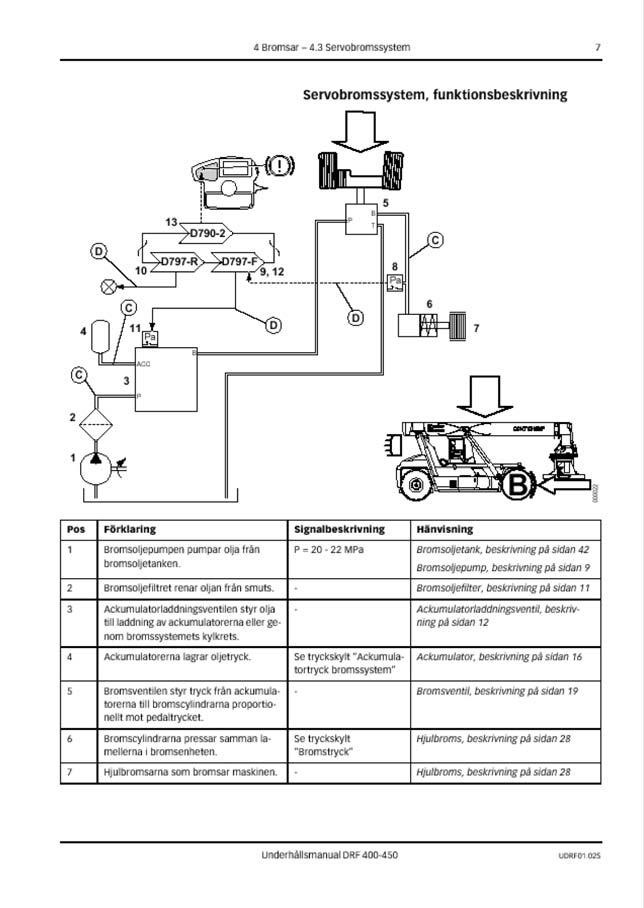
Function descriptions are schematic overviews that describe how a function works as well as which components and signals work together.
Function descriptions describe the function in a logical flow from input signal to desired output signal. Most functions require that preset conditions are fulfilled for the function to be activated. In these cases, the conditions are listed above the illustration.
Function descriptions use symbols to illustrate components such as valves, sensors, etc.
Example of function description
1.Hydraulic force (solid double line)
2.Flag pressure check connection (Check point), indicates that there is pressure check connection for checking pressure signal
3.Flag diagnostic test, indicates that signal can be checked with diagnostic test, see group “8.4 Diagnostics”
4.Illustration of function, (applied brake)
5.Reference to description of component
6.Signal description, reference value for signal out from component
7.Description of component's function
8.Position number, reference to position in illustration
9.Position number in illustration, reference to row in table
10.Electric power (solid single line)
Symbol explanation function descriptions
The following symbols are used in function descriptions, the symbols are based on standard symbols used in wiring and hydraulic diagrams.
1.Electric control signal
2.Electric force
3.Hydraulic control signal
4.Hydraulic force
5.Hydraulic motor
6.Hydraulic oil pump with variable displacement
7.Hydraulic oil pump with fixed displacement
8.Electric motor
9.Accumulator
10.Disc brake
11.Filter
12.Radiator
13.Bulb
14.Control and monitoring system, two control units with CAN bus
15.Restriction
16.Adjustable restriction
17.Inductive position sensor
18.Electrically controlled servo valve
19.Thermal by-pass valve
20.Temperature-controlled switch
21.Temperature sensor
22.Pressure sensor
23.Pressure-controlled switch
24.Hydraulic cylinder
25.Double-acting hydraulic cylinder
26.Spring brake cylinder
27. Valve block
28.Shuttle valve
29.Non-return valve
About the documentation
Documentation sections
The documentation to the machine comprises the following sections:
Operator's manual
The Operator's manual is supplied with the machine in the cab.
Documentation kit
Maintenance manual and spare parts catalogue with machine card are supplied with the machine as a separate documentation kit.
Supplementary documentation
There are Supplementary documentation that can be ordered for the machine. in the form of a Workshop manual. The Workshop manual includes supplier documentation for engine, transmission and drive axle.
•Workshop manual.
•Supplier documentation for engine, transmission and drive axle.
Ordering of documentation
Extra issues and supplementary documentation can be ordered from Kalmar Industries' dealers.
NOTE
If possible, always indicate publication number when ordering.
Workshop manual DRF 400–450
To: Kalmar Industries AB
Product Support
Torggatan 3
SE-340 10 Lidhult
SWEDEN
Fax: +46 372 263 93
Feedback
Form for copying
Kalmar Industries’ ambition is that you who work with maintenance of Kalmar machines shall have access to correct information. Your feedback is important to be able to improve the information. Copy this form, write down your views and send it to us. Thank you for your participation!
From:
Company / Sender: .............................................................................................................
Telephone: ....................................................................................................................
E-mail: .......................................................................................................................
Date: .................................... - .................. - ..................
Manual information
Name / Publication number: ....................................................................................................
Section / page number: ........................................................................................................ Suggestions, views, remarks, etc. .............................................................................................................................................................................
Workshop manual DRF 400–450
• Thank you very much for reading the preview of the manual.
• You can download the complete manual from: www.heydownloads.com by clicking the link below
• Please note: If there is no response to CLICKING the link, please download this PDF first and then click on it.