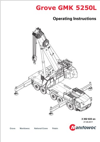
Operating Instructions 3 302 633 en 27.09.2017
• Thank you very much for reading the preview of the manual.
• You can download the complete manual from: www.heydownloads.com by clicking the link below
• Please note: If there is no response to CLICKING the link, please download this PDF first and then click on it.

CLICK HERE TO DOWNLOAD THE COMPLETE MANUAL
CLICK HERE TO DOWNLOAD THE COMPLETE MANUAL
Important note
Any type of duplication or excerpt from thisdocument, even in electronic form, isnotsubject to the revision service of Manitowoc Crane Group Germany GmbH
© Copyright reserved by Manitowoc Crane Group Germany GmbH Industriegelände West D-26389 Wilhelmshaven, Germany
Tel: [+49] (0)44 21 294-0
Fax: +[49] (0) 44 21 294-301
The passing on or duplication of this document as well as the utilisation and disclosure of its contents is prohibited unless expressly permitted. Infringement will incur liability for compensation. All rights pertaining to registration of patent or utility model are reserved. The original language of this document is German.
27.09.2017 3 302 633 enOperating Instructions GMK5250L
1 Reduction of slewing speed – can be switched on and off
In addition to the specifications in the lifting capacity table and operating manual supplied, the automatic reduction of the slewing speed can be switched off under certain conditions.
1.1 Important notes
These additional pages describe only this special function. Also observe all specifications and safety instructions in the Operating Instructions and lifting capacity table supplied.
GRisk of accidents due to excessive slewing speed!
Observe the specified maximum permissible slewing speeds. This prevents the truck crane from being subjected to excessive dynamic loads, which can lead to damage to crane sections and the truck crane overturning. Always slow down and accelerate the slewing movement slowly and avoid swinging loads. When reduction is switched off, you as crane operator are responsible for a slewing speed that is suitable the current loading case.
With reduction switched on
Depending on the degree of utilisation and the working radius, the slewing speeds are automatically reduced to the maximum permissible levels listed in the lifting capacity table under the comments on slewing speed.
With reduction switched off
If the maximum slewing speeds listed in the supplied lifting capacity table are exceeded, the buzzer tone sounds and a warning symbol is displayed. Theslewing speed is not reduced.
Additional page GMK3 302 652 en1 31.08.2017
1.2 Operation
1.2.1 Additional and modified operating elements
In the Superstructure lock menu
1 The display switches to this position – was previously at position (2)
–Operation
2 Slewing speed reduction on/off
–Display
3 Reduction on – green
4 Reduction off – grey
Menu-independent displays
Warning messages on the RCL display
–Blue: Reduction on
–Red: Maximum permissible slewing speed exceeded
31.08.2017 23 302 652 en Additional page GMK
1.2.2 Switching reduction off and on H
The reduction of the slewing speed is switched on with the ignition.
Switching reduction off
You can only switch off the reduction if the slewing range type Standard has been entered.
• Select and confirm the symbol (2).
–Display symbol (1) – green.
–Warning message display (3) – blue. The slewing speed is not reduced automatically.
If the maximum permissible slewing speed is exceeded, the buzzer tone sounds once and the warning message (3) is displayed –red
HThe entered limitations for the power unit speed of the slewing gear are still valid and the continuous speed reductions due to the working range limiter are still active.
Switching reduction on
• Select and confirm the symbol (2).
–Symbol (1) – grey displayed.
–The warning message (3) disappears. The slewing speed is reduced automatically. The reduction is automatically switched on when you enter the slewing range type MAXbase
Additional page GMK3 302 652 en3 31.08.2017
31.08.2017 43 302 652 en Additional page GMK
Blank page
Outrigger spans
Overview metres (feet) / per cent
The display RCL (1) shows the outrigger spans in metres (feet).
The control units (2) indicate the outrigger spans in per cent.
The percentage values in the enclosed lifting capacity table and the enclosed operating instructions deviate from the percentage values actually displayed on the control units (2) as they are based on different principles.
These additional pages give an overview for different crane types of what per cent you have to move the outrigger beams on the control units in order to obtain the desired outrigger span.
HDepending on the operating instructions supplied, the outrigger spans are given as the overall width or additionally as an individual width.
GMK5250L / GMK5200-1 / GMK5180-1
Additional pages GMK3 302 716 en1 08.02.2018
Length specificationsPercentages Overall widthsIndividual widths Control unit Lifting capacity table 7.800 m (25.6 ft)3.900 m (12.8 ft)100%100% 6.854 m (22.4 ft)3.427 m (11.2 ft)81%83% 5.910 m (19.4 ft)2.955 m (9.7 ft)63%66% 4.310 m (14.2 ft)2.155 m (7.1 ft)31%50% 2.710 m (8.8 ft)1.355 m (4.4 ft)0%0%
08.02.2018 23 302 716 en Additional pages GMK
Length specificationsPercentages Overall widthsIndividual widths Control unit Lifting capacity table 7.600 m (24.9 ft)3.800 m (12.5 ft)100%100% 6.700 m (22.0 ft)3.350 m (11.0 ft)83%83% 5.900 m (19.4 ft)2.950 m (9.7 ft)61%66% 5.100 m (16.7 ft)2.550 m (8.4 ft)51%50% 2.500 m (8.2 ft)1.250 m (4.1 ft)0%0% GMK4100L-1 Length specificationsPercentages Overall widthsIndividual widths Control unit Lifting capacity table 7.200 m (23.6 ft)3.600 m (11.8 ft)100%100% 6.250 m (20.6 ft)3.125 m (10.3 ft)81%80% 5.300 m (17.4 ft)2.650 m (8.7 ft)61%60% 3.800 m (12.4 ft)1.900 m (6.2 ft)31%40% 2.340 m (7.6 ft)1.170 m (3.8 ft)0%0% GMK3060 Length specificationsPercentages Overall widthsIndividual widths Control unit Lifting capacity table 6.20 m (20.3 ft)3.10 (10.2 ft)100% None 4.40 m (14.4 ft)2.20 (7.2 ft)51% 2.32 m (7.6 ft)1.16 (3.8 ft)0%
GMK5150/GMK5150L
Telescoping emergency programe
Return run of the telescoping cylinder
In the Operating manual supplied, it is noted that special care must be taken when telescoping in the emergency programe (1), as no automatic monitoring takes place.
If you move the telescoping cylinder without a telescopic section (return run), please also note all the information in these additional pages.
SRisk of damage during return run of the telescopic cylinder!
Always stop extending once the locking point on the outermost telescopic section has been reached.
This prevents damage to the boom system through a collision between the telescoping cylinder and the main boom head.
(A) – These specifications apply to the outermost telescopic section (3) – on all fixed lengths.
• Always stop extending the telescopic cylinder (1) once the locking point (2) on the outermost telescopic section (3) has been reached.
There is no automatic shutdown.
(B) – If you move too far past the locking point (2), the cylinder tube (4) will hit the main boom head(5) at the front.
This can lead to damage which makes telescoping the main boom no longer possible.
Additional pages GMK3 302 808 en1 31.08.2018
31.08.2018 23 302 808 en Additional pages GMK
Blank page
• Thank you very much for reading the preview of the manual.
• You can download the complete manual from: www.heydownloads.com by clicking the link below
• Please note: If there is no response to CLICKING the link, please download this PDF first and then click on it.
CLICK HERE TO DOWNLOAD THE COMPLETE MANUAL
CLICK HERE TO DOWNLOAD THE COMPLETE MANUAL
The operating instructions consist of the following chapters
1Overview
2Basic safety instructions
3Operating elements for driving
4Starting the engine for driving / switching it off
5Driving
6Driving modes and rigging for on-road driving
7Malfunctions in driving mode
8Operating elements for crane operation
9Starting/switching off the engine – for crane operation
10Crane operation
11Rigging work
12Driving with a rigged truck crane
13Transportation
14Malfunctions during crane operation
15Index
Operating Instructions GMK5250L3 302 633 en 27.09.2017
Blank page
3 302 633 enOperating Instructions GMK5250L 27.09.2017
Operating Instructions GMK5250L3 302 633 en 27.09.2017 1 1Overview 1.1Accidents . . . . . . . . . . . . . . . . . . . . . . . . . . . . . . . . . . . . . . . . . . . . . . . . . . . . . . . . . . 1 -1 1.2Branch offices. . . . . . . . . . . . . . . . . . . . . . . . . . . . . . . . . . . . . . . . . . . . . . . . . . . . . . . 1 -3 1.2.1Manitowoc Crane Care. . . . . . . . . . . . . . . . . . . . . . . . . . . . . . . . . . . . . . . . . . . . . . 1 -3 1.2.2Dealer list. . . . . . . . . . . . . . . . . . . . . . . . . . . . . . . . . . . . . . . . . . . . . . . . . . . . . . . . . 1 -3 1.3Warranty specifications . . . . . . . . . . . . . . . . . . . . . . . . . . . . . . . . . . . . . . . . . . . . . . 1 -3 1.4Terms used . . . . . . . . . . . . . . . . . . . . . . . . . . . . . . . . . . . . . . . . . . . . . . . . . . . . . . . . . 1 -4 1.5Technical data . . . . . . . . . . . . . . . . . . . . . . . . . . . . . . . . . . . . . . . . . . . . . . . . . . . . . . 1 -7 1.5.1Maximum lifting capacity (DIN/ISO/EN) . . . . . . . . . . . . . . . . . . . . . . . . . . . . . . . . 1 -7 1.5.2Maximum lifting capacity (ASME B 30.5). . . . . . . . . . . . . . . . . . . . . . . . . . . . . . . 1 -7 1.5.3Dimensions and weights of the truck crane, axle loads . . . . . . . . . . . . . . . . . . . 1 -8 1.5.4Dimensions and weights of removable parts. . . . . . . . . . . . . . . . . . . . . . . . . . . . 1 -10 1.5.5Carrier . . . . . . . . . . . . . . . . . . . . . . . . . . . . . . . . . . . . . . . . . . . . . . . . . . . . . . . . . . . 1 -15 1.5.6Superstructure . . . . . . . . . . . . . . . . . . . . . . . . . . . . . . . . . . . . . . . . . . . . . . . . . . . . 1 -19 1.6Documentation supplied . . . . . . . . . . . . . . . . . . . . . . . . . . . . . . . . . . . . . . . . . . . . . 1 -23 1.6.1Questions on documentation . . . . . . . . . . . . . . . . . . . . . . . . . . . . . . . . . . . . . . . . 1 -24 1.7Notes on the operating manual . . . . . . . . . . . . . . . . . . . . . . . . . . . . . . . . . . . . . . . 1 -25 1.7.1What do the symbols used mean? . . . . . . . . . . . . . . . . . . . . . . . . . . . . . . . . . . . . 1 -25 1.7.2How is the operating manual structured? . . . . . . . . . . . . . . . . . . . . . . . . . . . . . . 1 -27 1.7.3How do I find the information I need? . . . . . . . . . . . . . . . . . . . . . . . . . . . . . . . . . 1 -29 1.7.4What information is available for operations planning? . . . . . . . . . . . . . . . . . . 1 -32 1.8Conversion table for US measuring units . . . . . . . . . . . . . . . . . . . . . . . . . . . . . . . . 1 -33 1.9Training – Information. . . . . . . . . . . . . . . . . . . . . . . . . . . . . . . . . . . . . . . . . . . . . . . . 1 -35 1.10Identification . . . . . . . . . . . . . . . . . . . . . . . . . . . . . . . . . . . . . . . . . . . . . . . . . . . . . . . 1 -36 1.11EC Declaration of Conformity . . . . . . . . . . . . . . . . . . . . . . . . . . . . . . . . . . . . . . . . . . 1 -38
3 302 633 enOperating Instructions GMK5250L 27.09.2017
Operating Instructions GMK5250L3 302 633 en 27.09.2017 2 2Basic
instructions 2.1Intended use . . . . . . . . . . . . . . . . . . . . . . . . . . . . . . . . . . . . . . . . . . . . . . . . . . . . . . . 2 -1 2.1.1Improper use. . . . . . . . . . . . . . . . . . . . . . . . . . . . . . . . . . . . . . . . . . . . . . . . . . . . . . 2 -2 2.2Organisational measures . . . . . . . . . . . . . . . . . . . . . . . . . . . . . . . . . . . . . . . . . . . . . 2 -3 2.3Personnel qualifications . . . . . . . . . . . . . . . . . . . . . . . . . . . . . . . . . . . . . . . . . . . . . . 2 -5 2.4Safety instructions for driving the truck crane . . . . . . . . . . . . . . . . . . . . . . . . . . . . 2 -6 2.5Safety instructions for crane operation . . . . . . . . . . . . . . . . . . . . . . . . . . . . . . . . . . 2 -7 2.6Instructions on transporting persons . . . . . . . . . . . . . . . . . . . . . . . . . . . . . . . . . . . 2 -10
safety
3 302 633 enOperating Instructions GMK5250L 27.09.2017
3Operating elements for driving
Operating Instructions GMK5250L3 302 633 en 27.09.2017 3
3.1Overview of the operating elements . . . . . . . . . . . . . . . . . . . . . . . . . . . . . . . . . . . . 3 -1 3.1.1Exterior of the truck crane . . . . . . . . . . . . . . . . . . . . . . . . . . . . . . . . . . . . . . . . . . . 3 -2 3.1.2Driver's cab . . . . . . . . . . . . . . . . . . . . . . . . . . . . . . . . . . . . . . . . . . . . . . . . . . . . . . . 3 -6 3.1.3Steering column/steering wheel . . . . . . . . . . . . . . . . . . . . . . . . . . . . . . . . . . . . . . 3 -11 3.1.4Instrument panel. . . . . . . . . . . . . . . . . . . . . . . . . . . . . . . . . . . . . . . . . . . . . . . . . . . 3 - 13 3.1.5Transmission operating elements. . . . . . . . . . . . . . . . . . . . . . . . . . . . . . . . . . . . . 3 -17 3.1.6On-board computer . . . . . . . . . . . . . . . . . . . . . . . . . . . . . . . . . . . . . . . . . . . . . . . . 3 -18 3.1.7Tachograph. . . . . . . . . . . . . . . . . . . . . . . . . . . . . . . . . . . . . . . . . . . . . . . . . . . . . . . 3 -19 3.1.8Heating/Air-conditioning system. . . . . . . . . . . . . . . . . . . . . . . . . . . . . . . . . . . . . . 3 -20 3.1.9 CCS control unit . . . . . . . . . . . . . . . . . . . . . . . . . . . . . . . . . . . . . . . . . . . . . . . . . . . . 3 -24 3.1.10CCS – menu-dependent displays. . . . . . . . . . . . . . . . . . . . . . . . . . . . . . . . . . . . . . 3 -26 3.1.11CCS – Start menu . . . . . . . . . . . . . . . . . . . . . . . . . . . . . . . . . . . . . . . . . . . . . . . . . . 3 - 27 3.1.12CCS – Overview menu groups. . . . . . . . . . . . . . . . . . . . . . . . . . . . . . . . . . . . . . . . 3 -28 3.1.13Carrier menu group . . . . . . . . . . . . . . . . . . . . . . . . . . . . . . . . . . . . . . . . . . . . . . . . 3 -30 3.1.14Settings menu group . . . . . . . . . . . . . . . . . . . . . . . . . . . . . . . . . . . . . . . . . . . . . . . 3 -33 3.1.15Information menu group . . . . . . . . . . . . . . . . . . . . . . . . . . . . . . . . . . . . . . . . . . . . 3 -35 3.1.16Various controls menu group . . . . . . . . . . . . . . . . . . . . . . . . . . . . . . . . . . . . . . . . 3 -39 3.1.17Emergency operations menu group. . . . . . . . . . . . . . . . . . . . . . . . . . . . . . . . . . . 3 -39 3.1.18Outrigger control units. . . . . . . . . . . . . . . . . . . . . . . . . . . . . . . . . . . . . . . . . . . . . . 3 -40 3.1.19Sockets for hand-held control . . . . . . . . . . . . . . . . . . . . . . . . . . . . . . . . . . . . . . . . 3 -41 3.2Brief description of the operating elements . . . . . . . . . . . . . . . . . . . . . . . . . . . . . . 3 -43 3.2.1Definition of direction information . . . . . . . . . . . . . . . . . . . . . . . . . . . . . . . . . . . . 3 -44 3.2.2General rules for buttons and symbols on the display. . . . . . . . . . . . . . . . . . . . 3 -45 3.2.3Engine . . . . . . . . . . . . . . . . . . . . . . . . . . . . . . . . . . . . . . . . . . . . . . . . . . . . . . . . . . . 3 -46 3.2.4AdBlue system (DEF) . . . . . . . . . . . . . . . . . . . . . . . . . . . . . . . . . . . . . . . . . . . . . . . 3 -48 3.2.5Battery master switch. . . . . . . . . . . . . . . . . . . . . . . . . . . . . . . . . . . . . . . . . . . . . . . 3 -49 3.2.6Electrical system. . . . . . . . . . . . . . . . . . . . . . . . . . . . . . . . . . . . . . . . . . . . . . . . . . . 3 -50 3.2.7 CCS Crane control . . . . . . . . . . . . . . . . . . . . . . . . . . . . . . . . . . . . . . . . . . . . . . . . . . . . . . . 3 -51 3.2.8Transmission. . . . . . . . . . . . . . . . . . . . . . . . . . . . . . . . . . . . . . . . . . . . . . . . . . . . . . 3 -53 3.2.9Reverse camera. . . . . . . . . . . . . . . . . . . . . . . . . . . . . . . . . . . . . . . . . . . . . . . . . . . . 3 - 56 3.2.10BirdView system 270°. . . . . . . . . . . . . . . . . . . . . . . . . . . . . . . . . . . . . . . . . . . . . . . 3 -57 3.2.11Final drive . . . . . . . . . . . . . . . . . . . . . . . . . . . . . . . . . . . . . . . . . . . . . . . . . . . . . . . . 3 -59 3.2.12Brakes . . . . . . . . . . . . . . . . . . . . . . . . . . . . . . . . . . . . . . . . . . . . . . . . . . . . . . . . . . . 3 -61 3.2.13Steering / separate steering. . . . . . . . . . . . . . . . . . . . . . . . . . . . . . . . . . . . . . . . . . 3 -64 3.2.14Suspension . . . . . . . . . . . . . . . . . . . . . . . . . . . . . . . . . . . . . . . . . . . . . . . . . . . . . . . 3 -67 3.2.15Lighting/windscreen wipers/horn . . . . . . . . . . . . . . . . . . . . . . . . . . . . . . . . . . . . . 3 -68 3.2.16Level adjustment system. . . . . . . . . . . . . . . . . . . . . . . . . . . . . . . . . . . . . . . . . . . . 3 -72 3.2.17Tachograph/speedometer . . . . . . . . . . . . . . . . . . . . . . . . . . . . . . . . . . . . . . . . . . . 3 -74 3.2.18Diagnostics . . . . . . . . . . . . . . . . . . . . . . . . . . . . . . . . . . . . . . . . . . . . . . . . . . . . . . . 3 -75 3.2.19On-board computer . . . . . . . . . . . . . . . . . . . . . . . . . . . . . . . . . . . . . . . . . . . . . . . . 3 -76 3.2.20Windows, doors, keys . . . . . . . . . . . . . . . . . . . . . . . . . . . . . . . . . . . . . . . . . . . . . . 3 -78
• Thank you very much for reading the preview of the manual.
• You can download the complete manual from: www.heydownloads.com by clicking the link below
• Please note: If there is no response to CLICKING the link, please download this PDF first and then click on it.
CLICK HERE TO DOWNLOAD THE COMPLETE MANUAL
CLICK HERE TO DOWNLOAD THE COMPLETE MANUAL