
System Operation Manual
MD6640 Blast Hole Drill
Serial Number D612176 / 2U70A10 R
• Thank you very much for reading the preview of the manual.
• You can download the complete manual from: www.heydownloads.com by clicking the link below
• Please note: If there is no response to CLICKING the link, please download this PDF first and then click on it.


PREFACE
This Service Manual describes the technical features and servicing procedures for the KYMCO People GT 300i.
Section 1 contains the precautions for all operations stated in this manual. Read them carefully before any operation is started.
Section 2 is the removal/installation procedures for the frame covers which are subject to removal/installation frequency during maintenance and servicing operations.
Section 3 describes the inspection/ adjustment procedures, safety rules and service information for each part, starting from periodic maintenance.
Sections 5 to 12 give instructions for disassembly, assembly and adjustment of engine parts. Section 13 is the AFI system. Section 14 to 15 is the removal/ installation of chassis. Section 16 to 19 states the testing and measuring methods of electrical equipment.
Most sections start with an assembly or system illustration and troubleshooting for the section. The subsequent pages give detailed procedures for the section.
The information and contents included in this manual may be different from the motorcycle in case specifications are changed.

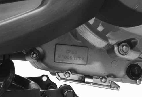
SERIAL NUMBER
1. GENERAL INFORMATION
SPECIFICATIONS
NamePeople GT 300i
Model No.BF60AA
Overall length2130 mm
Overall width750 mm
Overall height1280 mm
Wheel base1450 mm Engine type4 stroke O.H.C. Displacement298.9 cc
Oil filter typeFull-flow filtration
Oil capacity1.5 liter
Exchanging capacity1.3 liter
Fi injection system
Air cleaner type & NoPaper element, wet Fuel capacity9 liters
BrandKeihin
Throttle Body Butterfly type
Venturi diameter (mm) 34
Fuel pump pressure 3.0 bar
Curb weight (kg)
Max. weight (kg)
Starting systemStarting motor Type Gasoline 4-cycle
Cylinder arrangementSingle cylinder
Combustion chamber typeSemi-sphere
Valve arrangementO.H.C.-4V
Bore x stroke (mm) φ72.7 * 72
Compression ratio10.8:1
Compression pressure (kg/cm²-rpm) 16-570 rpm
Max. output (ps/rpm)28 / 7750
Max. torque (kg-m/rpm)2.7 / 6500
BTDC
BTDC
Idle speed (rpm) 1600±100 rpm
Cooling Type Liquid cooling
Lubrication type Forced pressure & wet sump
Oil pump typeInner/outer rotor
Electrical system
Ignition typeECU
Ignition timing ECU control
Spark plugCR7E (NGK)
Spark plug gap0.6~0.7mm
Battery Capacity12V12AH
Transmission system
Clutch type Dry multi-disc
Transmission type CVT
Operation typeAuto centrifugal
Reduction gear type Two-stage reduction
Reduction ratio Tire spec.
Primary2.24~0.72
Final7.222
Moving device
Tire type Tubeless
Front wheel 110/70-16
Rear wheel 140/70-16
Front wheel 1.75
Tire pressure (kg/cm²)
Rear wheel 2.25 (with passenger)
Wheel material Aluminium
Left45°±5
Turning angle
Brake type
Suspension type
Shock absorber
Right45°±5
FrontDisk brake
RearDisk brake
Damping Device
Front Telescope
RearSwing arm
Front110 mm
stroke Rear100 mm
SERVICE PRECAUTIONS
Make sure to install new gaskets, O-rings, circlips, cotter pins, etc. when reassembling.
Apply or add designated greases and lubricants to the specified lubrication points.
When tightening bolts or nuts, begin with larger-diameter to smaller ones at several times, and tighten to the specified torque diagonally.
When two persons work together, pay attention to the mutual working safety.
Use genuine parts and lubricants.
Disconnect the battery negative (-) terminal before operation.
When using a spanner or other tools, make sure not to damage the motorcycle surface.

When servicing the motorcycle, be sure to use special tools for removal and installation.
After operation, check all connecting points, fasteners, and lines for proper connection and installation.
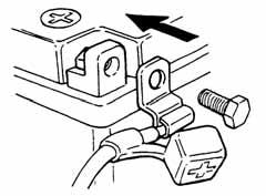
When connecting the battery, the positive (+) terminal must be connected first. After connection, apply grease to the battery terminals. Terminal caps shall be installed securely.
After disassembly, clean removed parts. Lubricate sliding surfaces with engine oil before reassembly.
If the fuse is burned out, find the cause and repair it. Replace it with a new one according to the specified capacity.

After operation, terminal caps shall be installed securely.
Before connecting a terminal, check for damaged terminal cover or loose negative terminal.
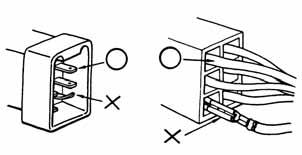
When taking out the connector, the lock on the connector shall be released before operation.
Check the double connector cover for proper coverage and installation.
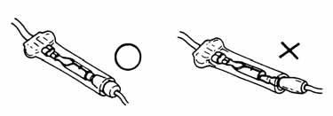
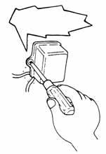
Hold the connector body when connecting or disconnecting it. Do not pull the connector wire.

Insert the terminal completely. Check the terminal cover for proper coverage.
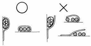
Do not make the terminal cover opening face up.
Check if any connector terminal is bending, protruding or loose.
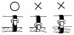
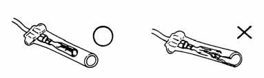
Secure wire harnesses to the frame with their respective wire bands at the designated locations. Tighten the bands so that only the insulated surfaces contact the wire harnesses.
The connector shall be inserted completely.
If the double connector has a lock, lock it at the correct position.
Check if there is any loose wire.
After clamping, check each wire to make sure it is secure.
Do not squeeze wires against the weld or its clamp.
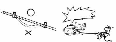
Do not pull too tight!
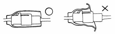
After clamping, check each harness to make sure that it is not interfering with any moving or sliding parts.
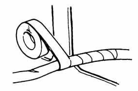
Protect wires and harnesses with electrical tape or tube if they contact a sharp edge or corner.
When rubber protector cover is used to protect the wire harnesses, it shall be installed securely.
When fixing the wire harnesses, do not make it contact the parts that will generate high heat.
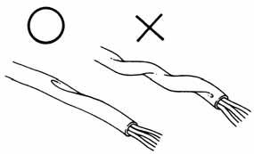
Do not break the sheath of wire. If a wire or harness is with a broken sheath, repair by wrapping it with protective tape or replace it.

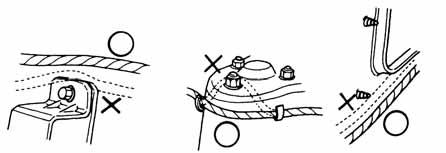
Route wire harnesses to avoid sharp edges or corners. Avoid the projected ends of bolts and screws.
Route wire harnesses passing through the side of bolts and screws. Avoid the projected ends of bolts and screws.
When installing other parts, do not press or squeeze the wires.
Route harnesses so they are neither pulled tight nor have excessive slack.
After routing, check that the wire harnesses are not twisted or kinked.
Do not press or squeeze the wire
Wire harnesses routed along with handlebar should not be pulled tight, have excessive slack or interfere with adjacent or surrounding parts in all steering positions.
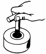
When a testing device is used, make sure to understand the operating methods thoroughly and operate according to the operating instructions.


Do you understand the instrument?
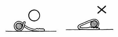
Be careful not to drop any parts.
When rust is found on a terminal, remove the rust with sand paper or equivalent before connecting.
Symbols:
The following symbols represent the servicing methods and cautions included in this service manual.

:Apply engine oil to the specified points. (Use designated engine oil for lubrication.)
:Apply grease for lubrication.
:Transmission Gear Oil (90#)
:Use special tool.
: Caution
: Warning
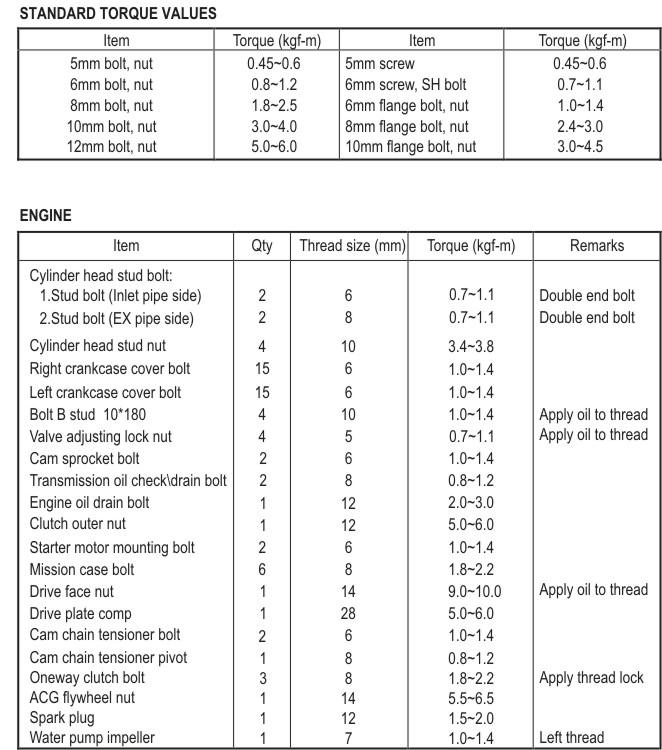
TORQUE VALUES
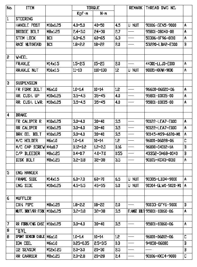
TORQUE VALUES FRAME
LUBRICATION POINTS FRAME
The following is the lubrication points for the frame. Use grease for parts not listed. Apply engine oil or grease to cables and movable parts not specified. It will avoid abnormal noise and damage the durability of the motorcycle.


• Thank you very much for reading the preview of the manual.
• You can download the complete manual from: www.heydownloads.com by clicking the link below
• Please note: If there is no response to CLICKING the link, please download this PDF first and then click on it.