

• Thank you very much for reading the preview of the manual.
• You can download the complete manual from: www.heydownloads.com by clicking the link below
• Please note: If there is no response to CLICKING the link, please download this PDF first and then click on it.

Important User Information
Solid state equipment has operational characteristics differing from those of electromechanical equipment. Safety Guidelines for the Application, Installation and Maintenance of Solid State Controls (Publication SGI-1.1 available from your local Rockwell Automation sales office or online at http://www.ab.com/manuals/gi) describes some important differences between solid state equipment and hard-wired electromechanical devices. Because of this difference, and also because of the wide variety of uses for solid state equipment, all persons responsible for applying this equipment must satisfy themselves that each intended application of this equipment is acceptable.
In no event will Rockwell Automation, Inc. be responsible or liable for indirect or consequential damages resulting from the use or application of this equipment.
The examples and diagrams in this manual are included solely for illustrative purposes. Because of the many variables and requirements associated with any particular installation, Rockwell Automation, Inc. cannot assume responsibility or liability for actual use based on the examples and diagrams.
No patent liability is assumed by Rockwell Automation, Inc. with respect to use of information, circuits, equipment, or software described in this manual. Reproduction of the contents of this manual, in whole or in part, without written permission of Rockwell Automation, Inc. is prohibited.
Throughout this manual, when necessary we use notes to make you aware of safety considerations.
WARNING
IMPORTANT
ATTENTION
Identifies information about practices or circumstances that can cause an explosion in a hazardous environment, which may lead to personal injury or death, property damage, or economic loss.
Identifies information that is critical for successful application and understanding of the product.
Identifies information about practices or circumstances that can lead to personal injury or death, property damage, or economic loss. Attentions help you:
• identify a hazard
• avoid a hazard
• recognize the consequence
SHOCK HAZARD Labels may be located on or inside the equipment (e.g. drive or motor) to alert people that dangerous voltage may be present.
BURN HAZARD Labels may be located on or inside the equipment (e.g. drive or motor) to alert people that surfaces may be dangerous temperatures.
Recommended Publications
The following publications supplement this manual. For more information and further reference, please use these available publications.
Publication Title
Arc-Resistant Low Voltage Motor Control Center Designs2100-AP003x-EN-P
Power Factor Correction Capacitors for Bulletin 2100 Motor Control Center Starter Units
Arc Flash Protection Marking Guide for CENTERLINE® Motor Control Centers
CENTERLINE® Motor Control Centers - Joining and Splicing Vertical Sections
Purchased Components and Additional Instruction Sheets
x-EN-P
x-EN-P
x-EN-P
Installing Units with Vertical Operating Handles2100-IN014x-EN-P
MCC NEMA Type 12 Sealing Instructions2100-IN037x-EN-P
Receiving Handling and Storing MCCs2100-IN040x-EN-P
HMCP Circuit Breakers2100-TD001x-EN-P
Thermal Magnetic Circuit Breakers2100-TD002x-EN-P
Power Fuses2100-TD003x-EN-P
DeviceNet Motor Control Centers2100-TD019x-EN-P
Service and Repair Guidance for Motor Control Centers2100-TD028x-EN-P
Installing Bulletin 2400 Horizontal Operating Handle2400-IN007x-EN-P
MCC Mains and Incoming Lines Reference2100-4.2
Installing a Pull Box on a Bulletin 2100 Vertical Section2100-5.28
(1) Some publication numbers contain a revision character ’x.’ This character will increase alphabetically with successive revisions. Always or der and use the latest revision available. The publication numbers that appear in this publication use x, as a placeholder for the revision letter. When referencing and/or ordering always use the latest revision available.
When equipment such as transformers, metering, PLCs or drives are supplied with the motor control center, specific manuals and data sheets are also supplied. These manuals and data sheets should be read and understood before installing and operating the motor control center. Refer to the unit locations of these devices for their manuals and/or data sheets.
General Description
General Information
Allen-Bradley CENTERLINE® Motor Control Centers (MCCs) consist of one or more vertical sections containing electromagnetic and/or solid state control devices that are prewired and tested within modular (plug-in) or frame mounted (hard-wired) units.
CENTERLINE Motor Control Centers are designed in standard widths of 20” (508 mm), 25” (635 mm), 30” (762 mm), 35” (789 mm) and 40” (1016 mm). The standard front-mounted depths of an MCC are 15” (381 mm) and 20” (508 mm), in addition back-to-back mounted depths of 30” (762 mm) and 40” (1016 mm) are also offered. The standard height of an MCC is 90” (2286 mm). A 70.5” (1791 mm) high section is also available. All MCC sections are supplied with top and bottom horizontal wireways. Most sections include vertical wireways. Each 90” vertical section can accommodate up to 6.0 space factors or 78” (1981 mm) for units.
Units (buckets) are designed in increments of 0.5 space factors. Each 0.5 space factor is approximately 6.5” (165.1 mm) high. Units are designed as either removable (plug-in) or frame-mounted (non-plug-in).
Individual units house a wide variety of power and logic devices. Plug-in units are mounted on unit support pans within the section. Stab assemblies located on the back of the unit plug onto the vertical bus. A mechanical interlock prevents the unit door from being opened while the unit is energized. An additional mechanical interlock prevents the unit from being plugged-in or unplugged when the disconnect is closed.
Line power is distributed throughout the MCC via an isolated bus work structure. The main horizontal bus is located in the center of each section. Standard, center-fed, 300 ampere rated vertical bus supplies power to the individual units above and below the horizontal bus for an effective 600 ampere capacity, allowing virtually unrestricted unit arrangement. An optional 600 ampere vertical bus provides 1200 ampere effective rating.
Nameplate Data
Each MCC section has a nameplate located on the enclosure or vertical wireway door. See Figure 1.1., section nameplate information includes:
• Catalog Number / Serial Number
• Series Letter of Section
• Bus Bar Voltage and Current Rating
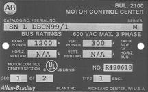
• Section Number
• UL and cUL Certification Marking
• UL Registration Number
• Enclosure Type
Figure 1.1 Section Nameplate
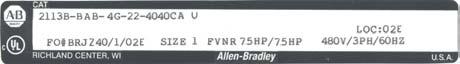
Each plug-in and frame mounted unit also has an identification label. The unit label is located on the interior of the bottom plate of plug-in units or on the interior right hand side plate of the frame mounted units, see Figure 1.2. The unit label for each plug-in or frame mounted unit includes:
• Catalog Number / Serial Number
• Series Letter of the Unit
• Voltage Rating
• Unit Location
• UL and cUL Certification Marking
• Device Type and Size
Figure 1.2 Unit Label
NOTE: The catalog number or serial number and series letter are required to properly identify the equipment to sales or factory personnel.
Motor Control Center Sequence Numbering

CENTERLINE Motor Control Centers are designed so functionality is not affected by the section installation order, i.e. vertical section numbering sequence order.
All MCC sections carry a serial plate which identifies vertical section sequence numbering, e.g. MCC section 1 of 1, 1 of 5, etc. See Figure 1.3.
Sections are numbered to match factory-supplied MCC elevation drawings. Numbering each section helps installers and users easily identify motor control centers, sections and units. If there are questions about section numbering during field installation, inspection or operation, the following instructions can provide guidance on equipment acceptability, listing and certification.
CENTERLINE MCC sections can be installed or added as follows:
1. In non-sequential order
2. Addition of a single section (add-on section)
3. Addition of multiple sections (add-on lineup of sections)
4. Addition of single section or multiple section between MCC sections.
If sections are added to an existing lineup and not installed in sequential order, the installation should not be considered a misapplication or in conflict with Underwriter Laboratories (UL) listing and Canadian Standards Association (CSA) certification.
The paramount criteria for additions of sections to existing MCCs is matching the horizontal bus electrical and ingress protection (enclosure type) ratings for the total MCC line up, i.e., the voltage, current rating, short circuit withstand and NEMA enclosure type (IP rating) for all sections must match.
Non-sequential numbering may not create a functional or listing/certification issue. However, motor control centers should be installed in sequential order. Installing MCCs in sequential order helps ensures proper installation and ensures that factory-supplied documentation matches the equipment.
UL/CSA Marking
CENTERLINE Motor Control Centers (MCCs) are listed by Underwriter’s Laboratories, Inc. (UL), Standard for Safety UL 845 and certified by the Canadian Standards Associate (CSA), Standard C22-2, No. 14.

Due to standards harmonization, a motor control center may also carry the cUL designation. cUL is comparable to CSA certification.
Vertical sections and units are labeled independently. It is possible to have combinations of labeled and non-labeled sections and units in the same motor control center.
Vertical sections and structure options that are UL listed and CSA/cUL certified are marked accordingly. All components in a UL or CSA listed section must be UL listed and cUL/CSA certified. The UL and/or CSA/cUL designation is an integral part of the section nameplate. See Figure 1.1.
Units and unit options that are UL listed and CSA/cUL certified are marked accordingly. All options and components in a UL and/or cUL/CSA listed unit must be UL listed or recognized and/or cUL/CSA certified. The UL designation is located on the interior of the bottom plate of plug-in units or on the interior right-hand side plate of frame mounted units. See Figure 1.4.
Short Circuit Rating Label
Motor control center vertical sections that are UL listed and/or CSA/cUL certified will carry a short circuit rating label. The short circuit rating label for a vertical section is located on the inside of the vertical wireway door of standard sections or on the interior right-hand side plate of special width sections. See Figure 1.5.

Motor control center units that are UL listed and/or CSA/cUL certified will carry a short circuit rating label located on the bottom plate of plug-in units or on interior right-hand side plate of frame mounted units. See Figure 1.6.

Series Number and Series ID as Manufactured in the U.S.
ATTENTION
Read Tables 1.A through 1.D BEFORE adding new sections or units to an existing CENTERLINE Motor Control Center.
Sections
A (1) —Original design February 1971
B (1) AllChanged terminal blocks
C (1) All Elimination of external mounting channels
D (1) All Reverse fed 2192’s and 2193’s
E (1) All All redesign gasketing
F (1) AllModified top horizontal wireway pan to accept units with handle interlock in topmost space factor
G (1) 42K42K bracing-incorporates new bus support & cover
G (1) 65K65K bracing-incorporates new bus support & cover
HAllNew hinge design
JAllChanged handle, operating mechanism and circuit breaker to Westinghouse series
KAllChanged to new unit grounding system 5.90
LAllChanged to new 600A - 1200A circuit breaker operating mechanism
MAllChanged to serpentine DeviceNet cabling system
(1) Replacement and renewal parts are no longer supported. Consult MCC Technical Support.
November 1976
June 1979
April 1981
October 1982
October 1983
January 1985
July 1985
January 1986
October 1986
May 1990
February 1996
May 2001
Table 1.B 2100 Units
2100 Units
A (1) —Original design
B (1) All sizesChanged terminal blocks
C (1) All sizesChanged handle mechanism to Cutler-Hammer/Westinghouse MCPs
D (1) Size 5Changed from ITE to A-B 400A disconnect
E (1) All sizesChanged from Bulletin 709 series K starters to Bulletin 500 line starters
F (1) All sizesRedesign of gasketing, wraparound and unit support pan for Bulletin 700 line
G (1) All sizesRedesign of gasketing, wraparound and unit support pan for Bulletin 500 line
H (1) All sizesChanged to new door, circuit breaker mechanism and control station
J (1) Size 5Changed to Bulletin 500 series L
February 1971
November 1976
June 1979
April 1981
April 1981
October 1982
October 1982
April 1984
October 1984 Size 3Changed to new PCP 100A disconnect
December 1988 Size 6Changed to Bulletin 500 series B starters
K Size 1-5 CB units and size 1-2 disc units
Changed handle, operating mechanism and circuit breaker to Cutler-Hammer/Westinghouse Series C, 150A, 250A and 400A frame
L 21A through 54AChanged to Bulletin 100 line contactors in 21A, 30A and 45A SMC units and original design 24A, 35A and 54A SMC units
MAll sizesChanged to new unit grounding system and 600A, 800A and 1200A bolted pressure switch
N All sizesChanged to PCP 200A and 400A disconnect, rerated vacuum Bulletin 2112 and 2113 and new pilot device offerings
P 0.5 SF CB units 2103L, 2113, 2193 External auxiliary on circuit breakers
October 1988
October 1986
November 1989
May 1990
January 1993
April 1994
QAll sizes and ratingsNew disconnect external auxiliary contacts and new 600A-1200A circuit breaker operating mechanismMay 1996
SMC unitsRedesign and upgrade of ratings for 24A-500A SMC-2 and SMC-PLUS units. Original design of SMC Dialog Plus units.
August 1997
R
1200A 2193Redesign of 1200A, 2193F and 2193M units
800A 2193Changed circuit breakers to MDL Frame
225A 2193FChanged circuit breakers from J Frame to F Frame
2000A 2193Changed to Flange Mounted Operating Handle
November 1997
November 1998
October 1999
November 2000
T
All sizesChanged the Bulletin 800MR and Bulletin 800T-PS pilot devices to Bulletin 800Es
U All except 2100-SD1Changed to new Bulletin 1497 control circuit transformer
November 2000
November 2000 All 1.5 space factor units Changed unit bottom plate
July 2001 2100-SD1Changed smoke detector head and base components
2162Q, 2163QRedesign of 240-480V PowerFlex 70 and release of 600V PowerFlex 70
2162R, 2163ROriginal release of 34A-56A PowerFlex 700
2154H, 2155HOriginal release of SMC-3
April 2002
July 2002
November 2001 V
Beginning November 2002
Beginning April 2004 2112, size 3, 4 and 5Redesign to reduced space factor with Class J fuse clip
2154J, 2155JOriginal release of SMC Flex
2162T, 2163TOriginal release of PowerFlex 40
(1) Replacement and renewal parts are no longer supported. Consult MCC Technical Support.
April 2004
September 2004
Series Lettering - Units & Sections
When using sections in conjunction with units of different series letters, consult the MCC Modifications for Unit and Structure Compatibility Table, Table 1.D, below.
(1) When installing unit in topmost location in vertical sections, care must be taken to comply with the 2005 National Electrical Code (reference code: Article 404.8 and UL 845) 6’7” (2000 mm) unit handle-to-floor height limitation. A unit operating handle extender (2100-NE1) is available which provides 3” (76.2 mm) added height flexibility.
(2) When Bulletin 2100, 0.5 space factor units are ordered unassembled or ordered for existing sections, a centralized wiring diagram holder kit (2100H-WDH) should be ordered.
(3) Permits installation of 0.5 space factor plug-in units in existing series E through J Bulletin 2100 vertical sections.
(4) Replacement and renewal parts are no longer supported. Consult MCC Technical Support at 1-800-646-5800
(5) Required only if series F or later, 1.0 space factor or larger Bulletin 2100 unit is installed in topmost location of series A through E vertical sections.
(6) Consult MCC Technical Support at 1-800-646-5800 for assistance with possible door hinge requirements.
(7) Series E-J sections cannot accommodate 0.5 space factor units in bottom-most unit location.
(8) A ground strap can be used to ground units rather then installing a ground bus. See publication 2100-IN014x-EN-P.
Receiving, Handling and Storage Receiving
As standard, CENTERLINE Motor Control Centers are shipped upright in shipping blocks of one to three front-mounted sections or two to six back-to-back sections. Each shipping block of an MCC is provided with a lifting angle. The lifting angle is optional on NEMA Type 3R and Type 4 MCCs. Each vertical section in a shipping block is bolted to the shipping skid and covered with clear plastic wrap. Equipment that extends from the structures is also protected. Protection is for upright shipping and is not waterproof or watertight. If necessary, other types of packaging are available.
Refer to publication 2100-IN040x-EN-P for receiving, handling and storage instructions. This publication is shipped with each MCC, attached to the outside of the MCC within the layer of clear plastic wrap. For additional information about the handling, installation, operation and maintenance of motor control centers rated more then not 600 volts, consult NEMA ICS 2.3-1995.
Export Packaging
A maximum of three vertical sections standing upright can be shipped with export packaging together in one block. The motor control center is bolted to a skid and wrapped in poly wrap suitable for occasional water-spray; a wooden frame and chipboard surround the sections. Export packaging is not watertight, waterproof or intended for long-term storage. Extended storage may require space heaters and other considerations. Export packing adds extra weight and dimensions to the shipping block.
• Thank you very much for reading the preview of the manual.
• You can download the complete manual from: www.heydownloads.com by clicking the link below
• Please note: If there is no response to CLICKING the link, please download this PDF first and then click on it.