Technical Manual
• Thank you very much for reading the preview of the manual.
• You can download the complete manual from: www.heydownloads.com by clicking the link below
• Please note: If there is no response to CLICKING the link, please download this PDF first and then click on it.

The policy of Bucyrus Europe Limited is one of continued improvement and, whilst every effort fs madeto ensure thatthis publication isuplodaleand coikm:! in all respect::. the right isreservedto change designs andspecificationsatany lime without notice


Introduction
Section 1 Mechanical Details
Construction
Machinery Air System
Section 2 Controls
Controls, Instruments, Indicators
Starting and Stopping Procedures
Alarm and Emergency Procedures Operating the Machine
Section 3 Rope Handling Rope Renewal
Section 4 Maintenance
Introduction and General recommendations
Planned Maintenance
Housekeeping
Routine Maintenance Schedule
Mechanical Components and assemblies
Brakes Air System
Electrics
Section 5 Changing the Boom Angle Without Boom Hoist With Boom Hoist
Hydraulic Tensioning Equipment
Section 6 Appendices

General
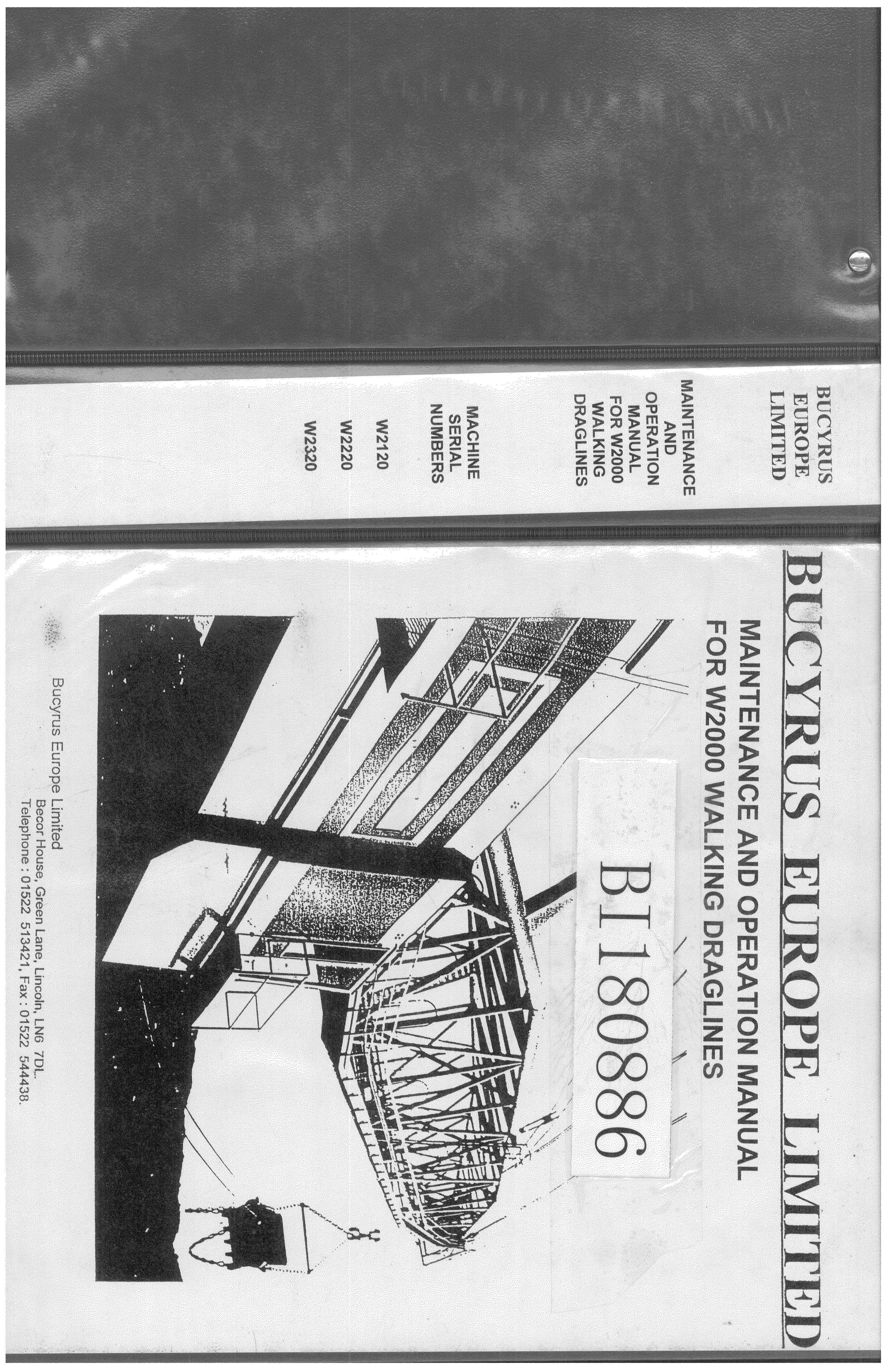
The BEML - BUCYRUS W2000 Walking Dragline is economically designed for high speed operation on continuous duty. All component partsaresubjecttorigidquality control and inspection during manufacture with special attention beinggiven to generous bearingsurfaces and ample provision for lubrication.
The Walking Dragline consists of abase, rotate frame, hoist, dragand swing gear, walk mechanism, boom and the bucket.
BASE
The base isa circular structure which provides the machine with alargeload bearing surface area. The base centre post is the axis of the rotate frame and conveys the drag force to the base when digging.
ROTATE FRAME
The rotate frame which supports the walk gear, house and front and equipment, is mounted on top of the baseandis driven by three motor/gearbox assemblies. Arollerring assembly supports the rotate frame on the base.
HOUSE
A dust-proof enclosure on top of the rotate framecalled the house, accommodates the drag and hoist machinery, swing boxes, walk motors, ail electrical control gear and most of the ancillary equipment.
The operator's cabisa separate unit fitted on the front of the machine house.
AH the above components are described in detail in Part 1.
DRIVES
Electrical power for the machine isfed via the trailing cable to a collectorassembly mounted on the base centre post. From here the power isfed to aHigh Voltage cubicle which houses the starting equipment for the motor/generator set synchronous motors and the isolator for the primary of the auxiliary transformer.
The four basic dragline motions are:
•It should be noted that the terms Swing and Rotate are synonymous and are used according to individual preference.

All motions are powered by d.c. motors fed from adjustable armature voltage generators. For swingandhoist motors there isanassociatedgenerator.Thedragandwalk motors are poweredbythesamegenerators;therequiredmotionbeingselectedbytheoperator.
Theoperator's pedals andleversprovideinfinitely variable control,uptothemaximum,for all motions.
Anannunciatorpanelinthe operator's cabprovidesvisualandaudiblewarningofcertainfault conditions. A further annunciator panelin the machine house provides visual warning of fault conditions.
BOOMS, BUCKETS
Achoice of four boom lengths isavailableand the machinecanberiggedfor either of two boom angles.Achoice of bucket sizesisalsoavailable,dependingon boom lengthandangle.
THE MAINTENANCE AND OPERATION MANUAL
ThisManualcomprisesfivePartsand contains all the mechanical information necessaryforthe safeand efficient operation of the machine.ThedescriptivePartisforgeneral information onlyandisnotintendedfororderingspareparts. Separate manuals cover Electrics, Lubrication Systems and Spare Parts.
Part1givesageneraldescription of themachine,anddetails of thecompressedairand ventilation systems.
Part 2 describes the various controls and instruments, start-up, shut-down and emergency procedures, and how to operate the machine.
Part3 covers rope handling and installation.
Part4 covers preventive maintenance and includes an inspection and maintenance schedule and details the various lubrication and adjustment procedures. Technical information covering the compressedairandelectrical systems isalsoincludedinthispart to facilitatefaultfinding.
Part5 covers the boom angle variations and the boom hoist systems.
At the end of this Manual, provision is made for the insertion of Appendices to cover changes indesign,special customer requirements, etc, whichmayoccur subsequent to the publication of this issue.

• Thank you very much for reading the preview of the manual.
• You can download the complete manual from: www.heydownloads.com by clicking the link below
• Please note: If there is no response to CLICKING the link, please download this PDF first and then click on it.

Safety
WARNING TO OPERATORS AND MAINTENANCE PERSONNEL

This Operators Manual is intended for the guidance of operators and individuals responsible forthe maintenance ofthis machine. Itis essential that operators familiarize themselveswith the controls and operating techniques before making any attemptto operate the machine. Precautions detailed throughoutthe Manual mustbestrictlyobserved.
OPERATING WITHIN MANUFACTURER'S LIMITS
It is the responsibility ofthe operator to ensure thatthe machine is operated withinthe manufacturer's limits; onno account should the specified maximum digging depth, dump height or suspended load be exceeded.
f* CHANGING BOOM ANGLE
When changing the boom angle, it is essential for the boom to be properly supported on suitable blocks or trestles when lowered to the horizontal.
OVERHEAD POWER LINES
Regard every overhead line as being electrically live unless you have it in writing from the Electricity Authority that itis not.
Extreme care mustbetakenwhenthe machine has to operate near overhead line which cannot be made dead, since inadvertent rotation ofthe boom may introduce danger. It should also benotedthata dangerous condition can arise even when theboomis several feet away from the overhead line.
Where digging or dumping must be carried out in close proximity to overhead electric lines, special care should betakento ascertain the height or closeness ofthe overhead lines. Remember thatit is difficult to estimate the height of lines by normal methods of C observation.


• Thank you very much for reading the preview of the manual.
• You can download the complete manual from: www.heydownloads.com by clicking the link below
• Please note: If there is no response to CLICKING the link, please download this PDF first and then click on it.