Technical Manual
• Thank you very much for reading the preview of the manual.
• You can download the complete manual from: www.heydownloads.com by clicking the link below
• Please note: If there is no response to CLICKING the link, please download this PDF first and then click on it.


TABLE OF CONTENTS

SAFETY PRECAUTIONS
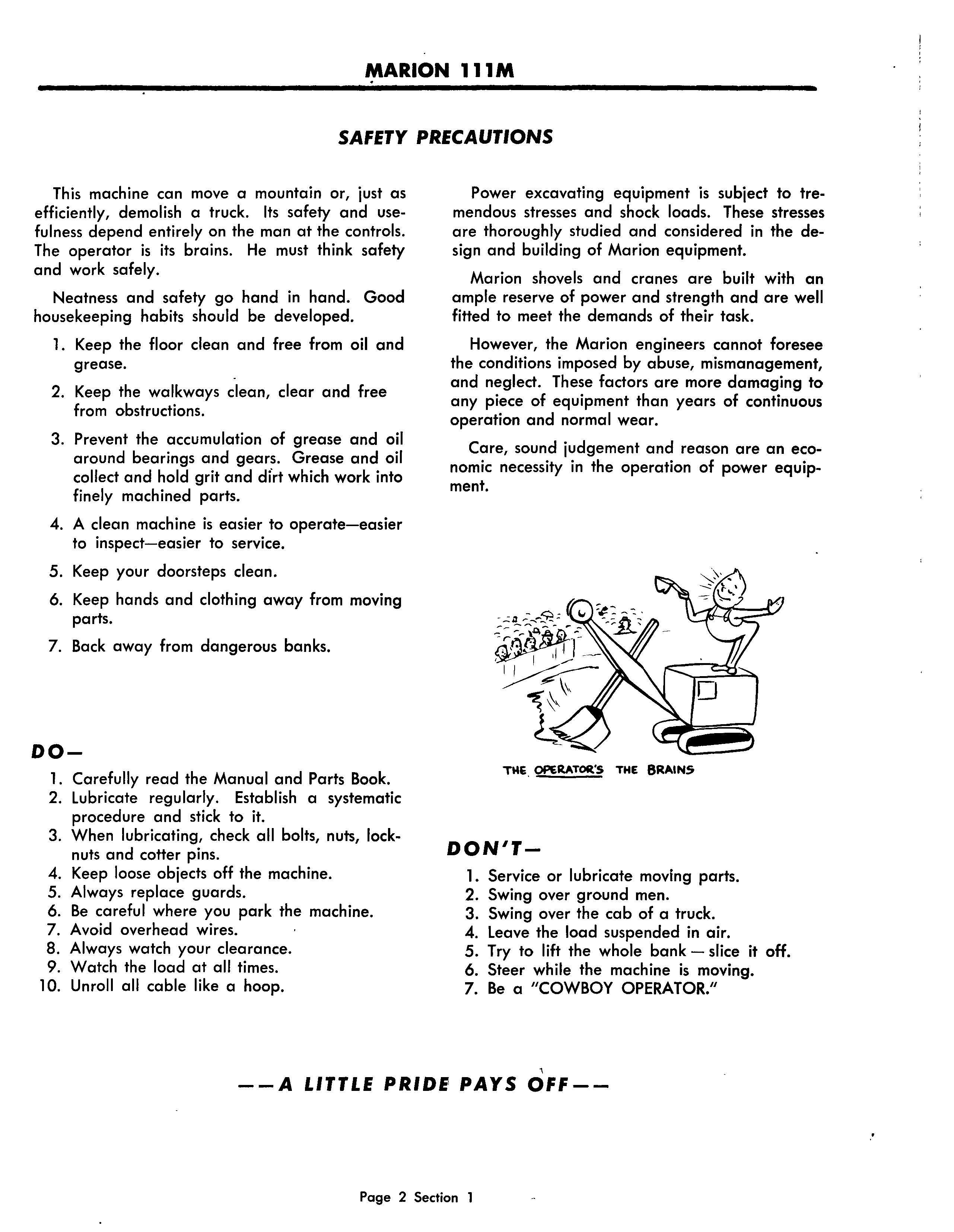
This machine can move a mountain or, just as efficiently, demolish a truck. Its safety and usefulness depend entirely on the man at the controls. The operator is its brains. He must think safety and work safely.
Neatness and safety go hand in hand. Good housekeeping habits should be developed.
1. Keep the floor clean and free from oil and grease.
2. Keep the walkways clean, clear and free from obstructions.
3. Prevent the accumulation of grease and oil around bearings and gears. Grease and oil collect and hold grit and dfrt which work into finely machined parts.
4. A clean machine is easier to operate-easier to inspect-easier to service.
5. Keep your doorsteps clean.
6. Keep hands and clothing away from moving parts.
7. Back away from dangerous banks.
DO-
l. Carefully read the Manual and Parts Book.
2. Lubricate regularly. Establish a systematic procedure and stick to it.
3. When lubricating, check all bolts, nuts, locknuts and cotter pins.
4. Keep loose objects off the machine.
5. Always replace guards.
6. Be careful where you park the machine.
7. Avoid overhead wires.
8. Always watch your clearance.
9. Watch the load at all times.
10. Unroll all cable like a hoop.
Power excavating equipment is subject to tremendous stresses and shock loads. These stresses are thoroughly studied and considered in the design and building of Marion equipment.
Marion shovels and cranes are built with an ample reserve of power and strength and are well fitted to meet the demands of their task.
However, the Marion engineers cannot foresee the conditions imposed by abuse, mismanagement, and neglect. These factors are more damaging to any piece of equipment than years of continuous operation and normal wear.
Care, sound judgement and reason are an economic necessity in the operation of power equipment.
DONIT-
1. Service or lubricate moving parts.
2. Swing over ground men.
3. Swing over the cab of a truck.
4. Leave the load suspended in air.
5. Try to lift the whole bank - slice it off.
6. Steer while the machine is moving.
7. Be a "COWBOY OPERATOR,'I
SECTION 1
GENERAL INFORMATION
INTRODUCTION
This manual is provided for the guidance of all persons who operate, lubricate, adjust or maintain the Marion Type 111M The information was prepared with the purpose in mind of furnishing accurately and concisely all data necessary to the operation and servicing of not only the basic machine but also of the various front end attachments.
All information, measurements and specifications herein are in accord with the Marion Power Shovel Engineering Department and should be strictly adhered to in all work on this machine.
PARTS BOOKS
This manual is not a parts book and should not be used in ordering parts. You have been furnished detailed Parts Books which list all parts by group numbers, with item and parts numbers for your specific machine.
When ordering parts, it is necessary that all the following information accompany each order:
Type
Serial Number
Group Number
Description
Part Number
Item Number
SERIAL NUMBER OF MACHINE
Be sure that the serial number of the machine is given in any letters, telegrams, orders or other communications. Records for each individual machine are filed by serial number and if this number is available, the design and original equipment can be quickly and accurately checked.
The serial number of the machine will be found on a name plate inside the cab. In case this plate is missing, the machine can be identified from the make and serial number of the engine if the engine is the one originally installed in the machine. If the serial number of the machine or of the original engine is not available, the machine may still be identi(;ed if the names of the previous owners can be furnished.
RIGHT AND LEFT HAND PARTS
On the upper frame, right hand (r.h.) and left hand (I.h.) correspond to the operator's right and left hands when he is facing, forward. On the crawler mounting, standing at the rear, or driving end, and facing forward, right hand and left hand correspond to your own right and left hands.
ORDERING PARTS
The Parts Book covering this machine gives complete information on how to order parts. Order carefully so that the right parts in the right quantities can be furnished. Wrong parts, ordered by mistake, which are returned to the Company are subject to a rehandling charge.
FURTHER INFORMATION
If further information is required which is not found in this Manual or in the Parts Book, communicate with your District Salesman, District Sales Manager, Marion Distributor or with the Company at Marion, Ohio.
STANDARD WARRANTY
MARION POWER SHOVEL COMPANY guarantees the parts manufactured by it to be free from defects in material and workmanship under normal use and service, its obligation under this warranty being limited to making good at its factory any part or parts thereof manufactured by it which shall, within six (6) months after delivery of said machine to the original purchaser, be returned to it with transportation charges prepaid, and which its examination shall disclose to its satisfaction to have been thus defective; this warranty being expressly in lieu of all other warranties expressed or implied, and of all other obligations or liabilities on MARION POWER SHOVEL COMPANY'S part.
CHARGES FOR SERVICE, LABOR, ETC.
No charges for service or labor are accepted unless the work has been previously authorized by the Company in writing. •
Section 2
AIR SYSTEM COMPONENT PARTS
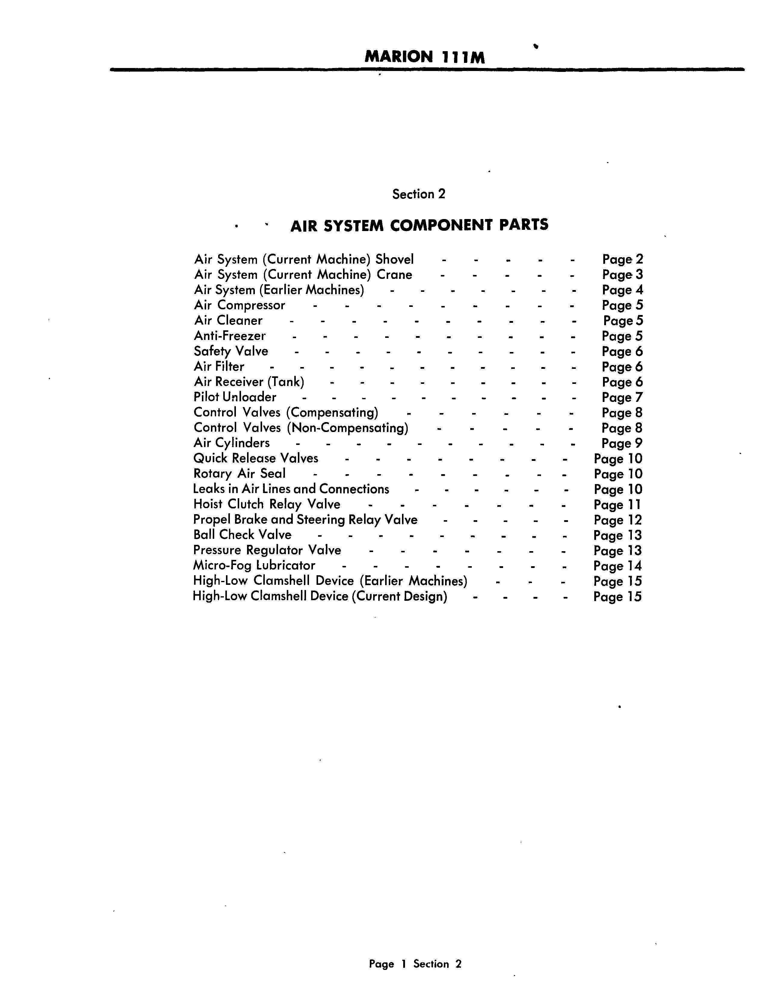
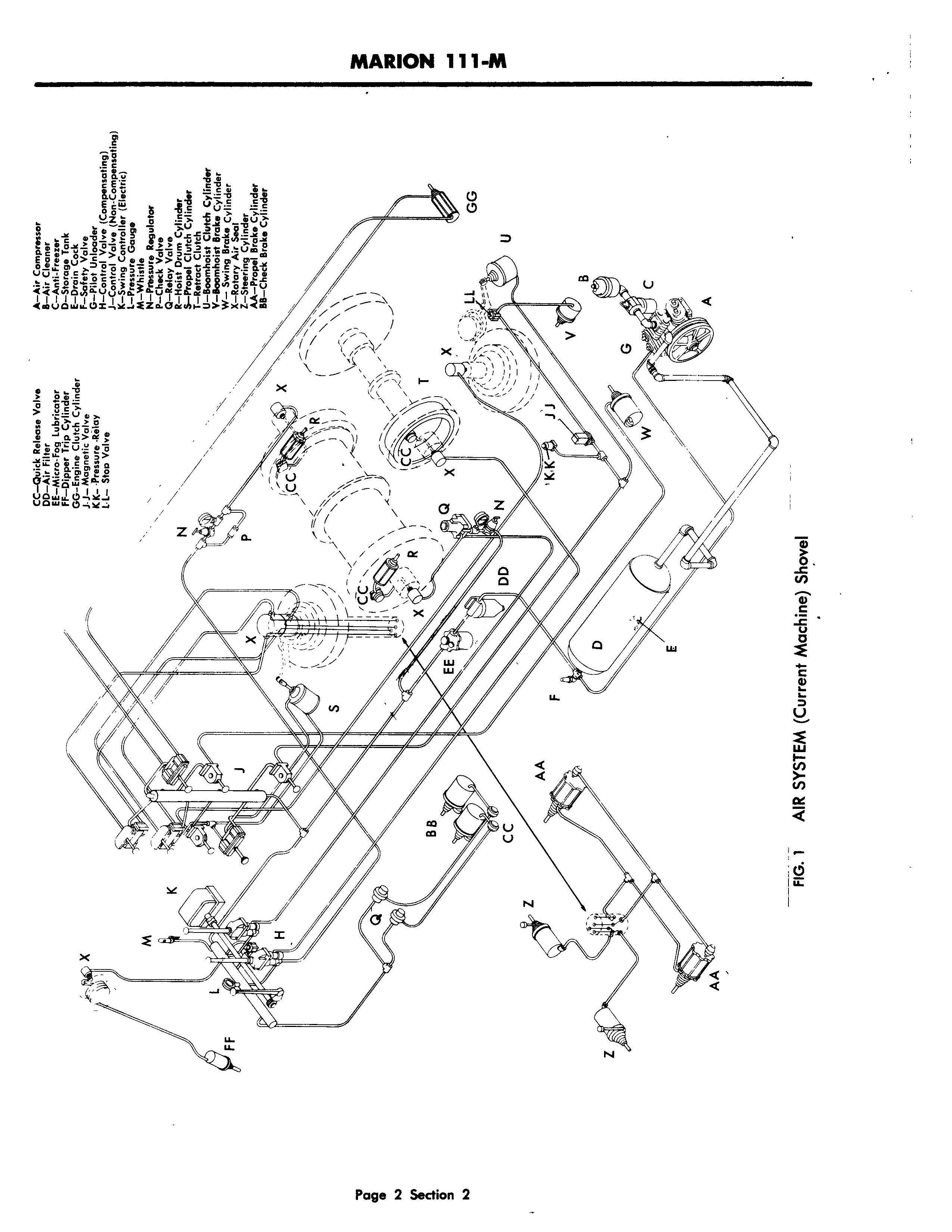
Air System (Current Machine) Shovel
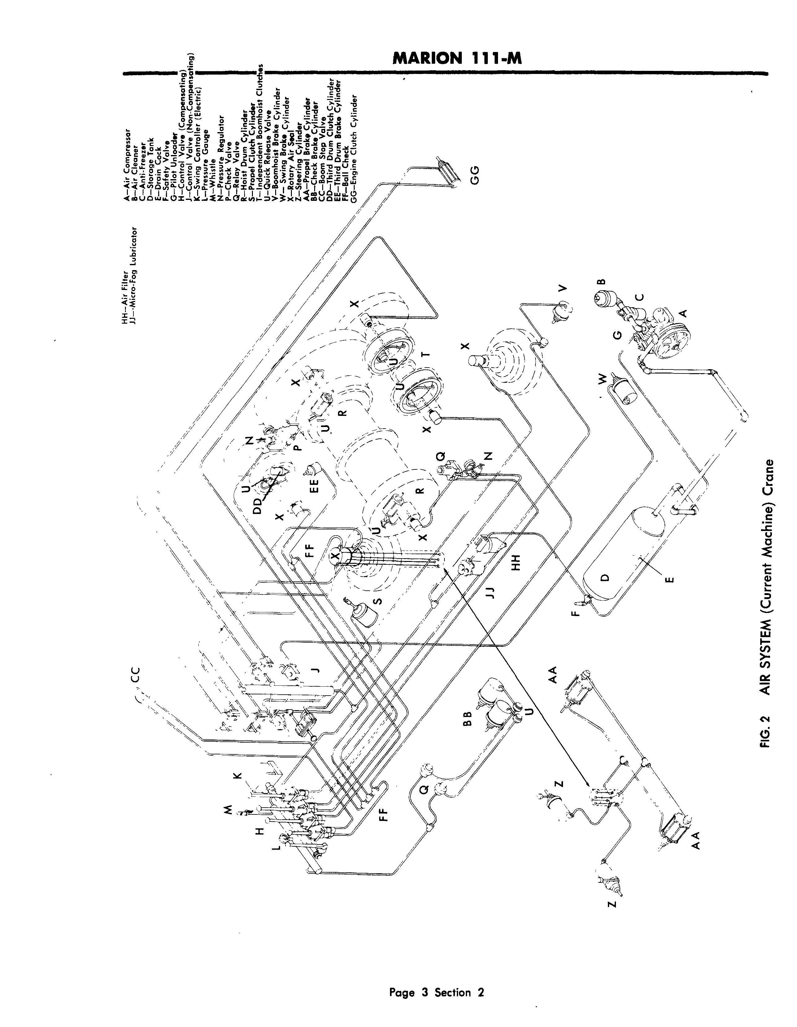
Air System (Current Machine) Crane
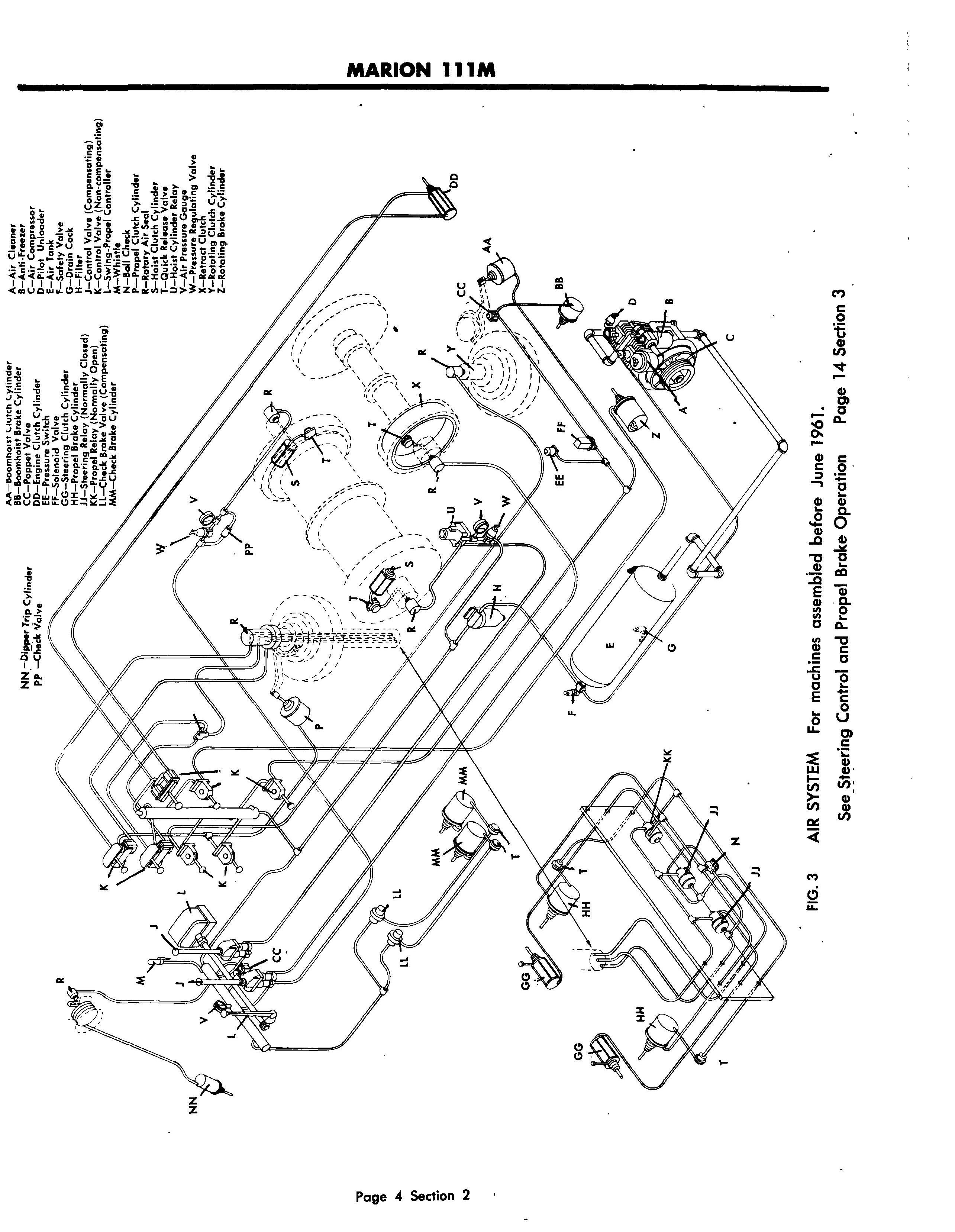
Air System (Earlier Machines)
Air Compressor
Air Cleaner
Anti-Freezer
Safety Valve
Air Filter
Air Receiver (Tank)
Pilot Unloader
Control Valves (Compensating)
Control Valves (Non-Compensating)
Air Cylinders
Quick Release Valves
Rotary Air Seal
Leaks in Air Lines and Connections
Hoist Clutch Relay Valve
Propel Brake and Steering Relay Valve
Ball Check Valve
Pressure Regulator Valve
Micro-Fog Lubricator
High-Low Clamshell Device (Earlier Machines)
High-Low Clamshell Device (Current Design)
Page 2
Page 3
Page 4
Page 5
Page5
Page 5
Page 6
Page 6
Page 6
Page 7
Page 8
Page 8
Page 9
Page 10
Page 10
Page 10
Page 11
Page 12
Page 13
Page 13
Page 14
Page 15
Page 15
SECTION 2
AIR CONTROL COMPONENT PARTS
AIR SYSTEM
The operation of- the Marion Type 111 M Power Shovel is controlled by an air system that provides a positive and smooth response in 'the action of the controls. All movement ofthe machine, except the electric swing-propel, is controlled by compressed air through an arrangement of valves and cylinders. In other words, in the Marion air control system, copper lines and rubber hose replace rods, links and pins which have to be manually operated and which, from wear, cause lost motion and operator fatigue.
The Marion air control system is simple in operation and with reasonable care and maintenance it will have a long and trouble-free service life. The air control can best be explained by a brief description of its components and their functions in the system.
AIR COMPRESSOR
The air compressor supplies air for the entire system and upon its proper functioning depends the efficiency of all the component units. Regular care and inspection ofthe compressor are vital to the efficient operation of the shovel. The compressor maintains air pressure in the system at between 90 psi and 110 psi. When adjusted correctly, as air pressure drops to 90 psi, the compressor cuts in and fills the system; as air pressure reaches 110 psi, the compressor cuts out and idles.
Several manufacturers supply Marion with compressors and for detailed information, reference should be made to the manufacturer's specifications and instructions to be found itt- the back of this Manual. The following instructions, however, should be followed, regardless ofthe make.
V-BELT TENSION-The compressor: is driven by three matched V belts directly from the engine. V belts transmit their drive to the pulley from the sides of the belt-not from the bottom of the belt; and for this reason, V belts should never be allowed to bottom in the pulley groove. Correct belt tension is important and should be constantly maintained. A belt that is too loose will slip on the pulley and will fail to deliver the required air pressure; a belt that is too tight will damage bearings through the excessive load. To determine the correct belt tension, depress the belt with the thumb at a point midway between the two
pulleys. When the belt can be depressed approximately 3,41/, the tension is considered correct.
To adjust belt tension, loosen the hold-down Dolts ore or two turns, then turn the jack screws so as to move the compressor up to or away from the power unit pulley, as required. When proper tension is secured, tighten the hold-down bolts firmly.
At all times keep the belts clean and free from oil or grease. Replace belts as soon as they show any sign of wear or deterioration. (See Repair List.)
COOLING FINS - Inspect the compressor cooling fins frequently and remove any dirt or debris that may have accumulated. Dirty fins can cause the compressor to overheat.
LUBRICATION OF COMPRESSOR - Check the oillevel daily. For grades and kinds of lubricants see the Oil Specification on Page 6 ,. Section 3.
AIR CLEANER
The air cleaner, located at the compressor, is the intake source of air to the compressor. Remove and clean air cleaner at regular intervals as conditions require and immerse in oil, same grade and kind as used in the compressor crank case. Drain excess oil from filter and replace unit. In dusty conditions, clean and oil daily.
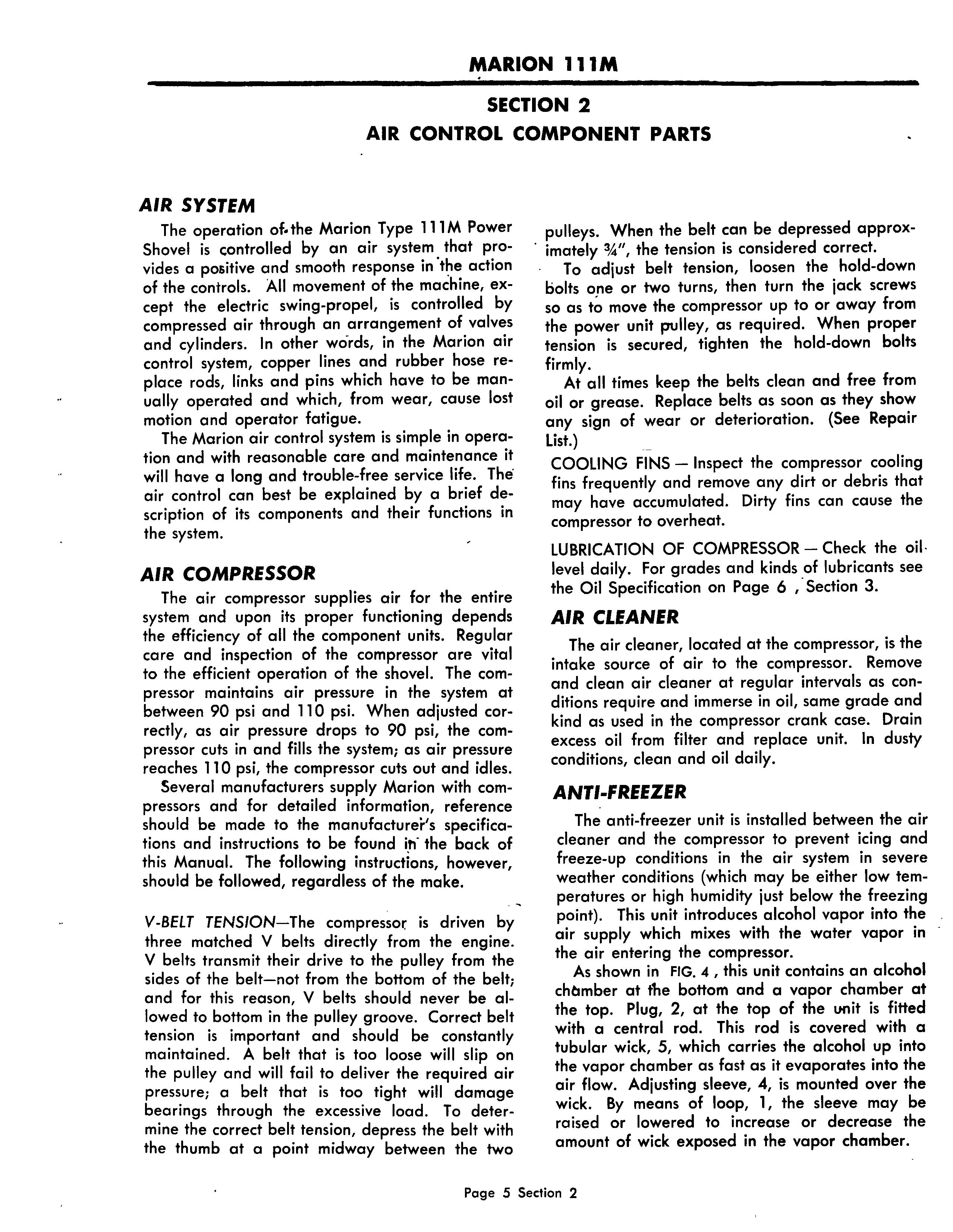
ANTI-fREEZER
The anti-freezer unit is installed between the air cleaner and the compressor to prevent icing and freeze-up conditions in the air system in severe weather conditions (which may be either low temperatures or high humidity just below the freezing point). This unit introduces alcohol vapor into the air supply which mixes with the water vapor in the air entering the compressor.
As shown in FIG. 4, this unit contains an alcohol chtsmber at the bottom and a vapor chamber at the top. Plug, 2, at the top of the unit is fitted with a central rod. This rod is covered with a tubular wick, 5, which carries the alcohol up into the vapor chamber as fast as it evaporates into the air flow. Adjusting sleeve, 4, is mounted over the wick. By means of loop, 1, the sleeve may be raised or lowered to increase or decrease the amount of wick exposed in the vapor chamber.
ADJUSTMENT AND MAINTENANCE-In severe weather, the sleeve should be lowered to the maximum depth, leaving the wick completely exposed in the vapor chamber. As the temperature moderates, the sleeve should be raised to reduce the amount of wick exposed, thus vaporizing less alcohol. When the temperature is above freezing, the sleeve should be raised to the maximum height which will cut off the alcohol supply to the vapor chamber. The frequency of refilling depends on weather conditions and the hours the machine is operated.
ALCOHOL-Use only METHYL alcohol, distilled from wood. Thorough investigations prove that Ethyl alcohol is unfit for use. DO NOT USE RADIATOR ANTI-FREEZE.
SAFETY VALVE
A pop valve is installed at the end of the tank as a safety factor with an initial blow off at 145 psi, if the unloader valve fails to function.
AIR FILTER
The air filter, FIG. 5 is located in the air line between the receiver tank and the operating manifold. The purpose of the filter is to prevent moisture and fine particles from entering the system and damaging the control valves.
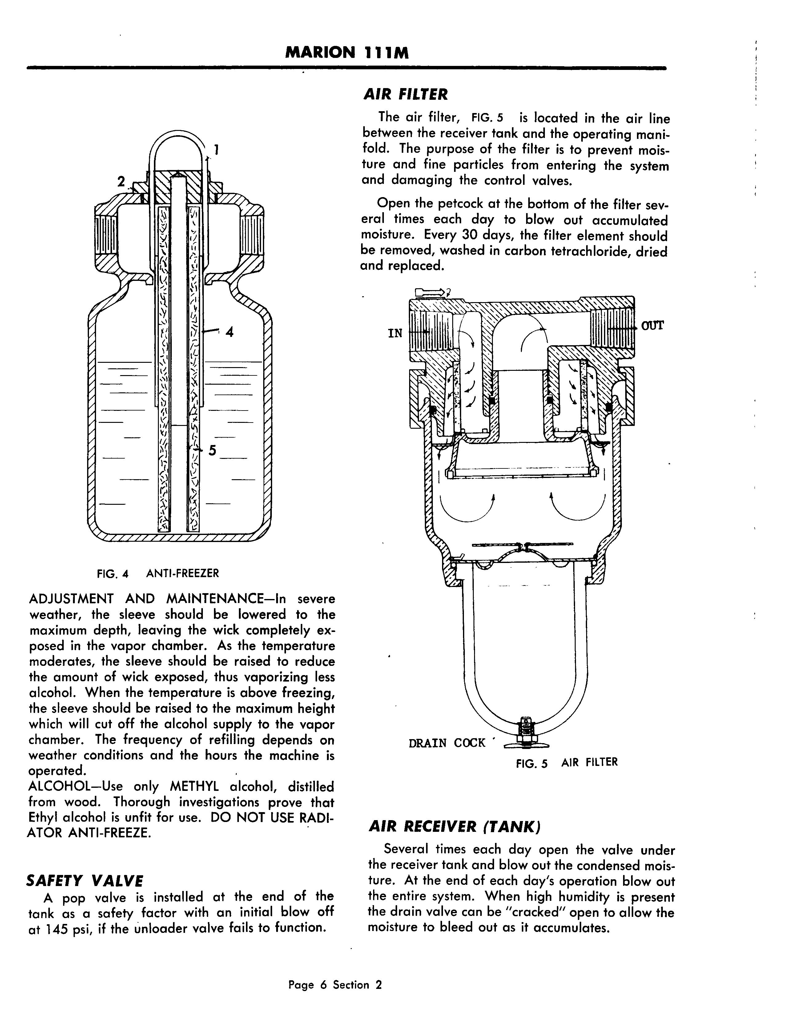
Open the petcock at the bottom of the filter several times each day to blowout accumulated moisture. Every 30 days, the filter element should be removed, washed in carbon tetrachloride, dried and replaced.
AIR RECEIVER (TANK)
Several times each day open the valve under the receiver tank and blowout the condensed moisture. At the end of each day's operation blowout the entire system. When high humidity is present the drain valve can be "cracked" open to allow the moisture to bleed out as it accumulates.
MARION 111M
PILOT UNLOADER VALVE
The pilot unloader valve is located at the outlet end of the receiver tank and is connected to the suction valve of the compressor. Air at maximum pressure passes through the un loader valve to the compressor where it holds the suction valve open until air pressure in the air tank is lowered. The unloader valve then closes and permits the compressor to build up air pressure in the tank.
The unloader valve should not be tampered with unless all indications point to its being out of adjustment. It is set at the factory to unload at approximately 110 psi. and to start pumping again at 90 psi.
PILOT UNLOADER VALVE ADJUSTMENT - If it becomes necessary to adjust the unloader valve, proceed as follows: Remove the acorn cap nut on top of the valve, then loosen locknut and turn the adjusting screw clockwise, or into the valve body, to increase top operating pressure. Turn adjusting screw counterclockwise to decrease top operating pressure. When desired unloading pressure is secured, tighten the locknut and replace acorn cap nut. NOTE: The differential between load and unload is built into the valve spring. The top operating pressure only can be set by the adjusting screw. Recommended top pressure is 110 psi. Compressor should load at approximately 90 psi. with this setting.

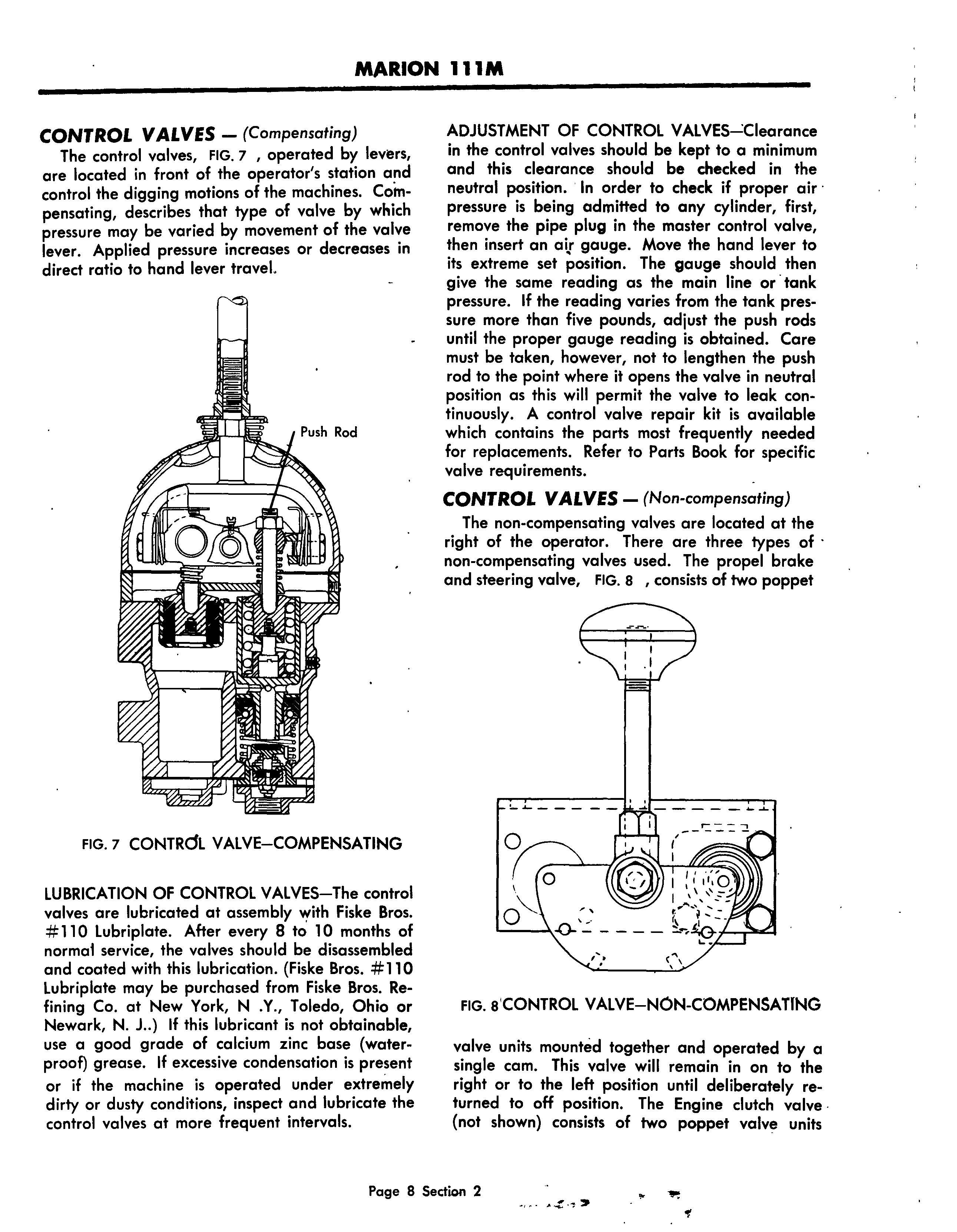
CONTROL VALVES - (Compensating)
The control valves, FIG. 7, operated by levers, are located in front of the operator's station and control the digging motions of the machines. Compensating, describes that type of valve by which pressure may be varied by movement of the valve lever. Applied pressure increases or decreases in direct ratio to hand lever travel.
lU BRICATION OF CONTROL VALVES-The control valves are lubricated at assembly Vfith Fiske Bros. # 110 lubriplate. After every 8 to 10 months of norma1 service, the valves should be disassembled and coated with this lubrication. (Fiske Bros. #110 lubriplate may be purchased from Fiske Bros. Refining Co. at New York, N.Y., Toledo, Ohio or Newark, N. L) If this lubricant is not obtainable, use a good grade of calcium zinc base (waterproof) grease. If excessive condensation is present or if the machine is operated under extremely dirty or dusty conditions, inspect and lubricate the control valves at more frequent intervals.
ADJUSTMENT
OF
CONTROL VALVES--':Clearance in the control valves should be kept to a minimum and this clearance should be checked in the neutral position. In order to check if proper air' pressure is being admitted to any cylinder, first, remove the pipe plug in the master control valve, then insert an ait gauge. Move the hand lever to its extreme set position. The gauge should then give the same reading as the main line or' tank pressure. If the reading varies from the tank pressure more than five pounds, adjust the push rods until the proper gauge reading is obtained. Care must be taken, however, not to lengthen the push rod to the point where it opens the valve in neutral position as this will permit the valve to leak continuously. A control valve repair kit is available which contains the parts most frequently needed for replacements. Refer to Parts Book for specific valve requirements.
CONTROL VALVES - (Non-compensating)
The non-compensating valves are located at the right of the operator. There are three types of non-compensating valves used. The propel brake and steering valve, FIG. S, consists of two poppet
units mounted together and operated by a Single cam. This valve will remain in on to the right or to the left position until deliberately returned to off position. The Engine clutch valve· (not shown) consists of two poppet valve units
mounted together and are by a rocker bar. This valve must be held in on position and will return to off position when the handle is released.
The shovel dipper trip valve is a single poppet valve mounted on the side of the crowd-retract operating valve. The handle of the operating valve is moved to the right to actuate the dipper trip.
No adjustments are required for the non-compensating valves. A repair kit is available for these valves which contains the parts most freqently needed for replacement. Refer to your parts book for specific requirements.
AIR CYLINDERS
Air cylinders, FIG. 10 , are located at various points in the air control system to actuate the movement of the machine. The operation of all air cylinders are similar and the maintenance required (except for lubrication as explained below) is mini mum. Two types are used here; Single acting in which the piston rod is pushed or pulled in one direction, air being admitted at either end. And the double acting cylinder where the piston rod is moved in both directions by air pressure, air being admitted alternately at both ends of the cylinder.

All other non-compensating valves, FIG. 9, in the auxiliary control panel are single diaphragm type valves operated by a cam on the valve handle. These valves will remain in on or off position.
LUBRICATION OF AIR CYLINDERS; Air cylinders are lubricated at assembly with ELCO # 158-LO. Everyone or two months all air cylinders should be lubricated with a small amount of neats-foot oil or clean non-detergent motor oil as follows: Release the air pressure in the system. The air that supplies each air cylinder is assembled with a pipe tee near the cylinder. By removing the pipe plug in the tee, lubricating oil can be introduced into the cylinder. The pipe tee provided to lubricate the air cylinder of the lower frame (steering and propel brakes) are located on the upper frame next to the rotary air seal on the center journal. Pour into each pipe tee approximately one half teaspoonful of neats-foot oil or motor oil, and replace the pipe plug.
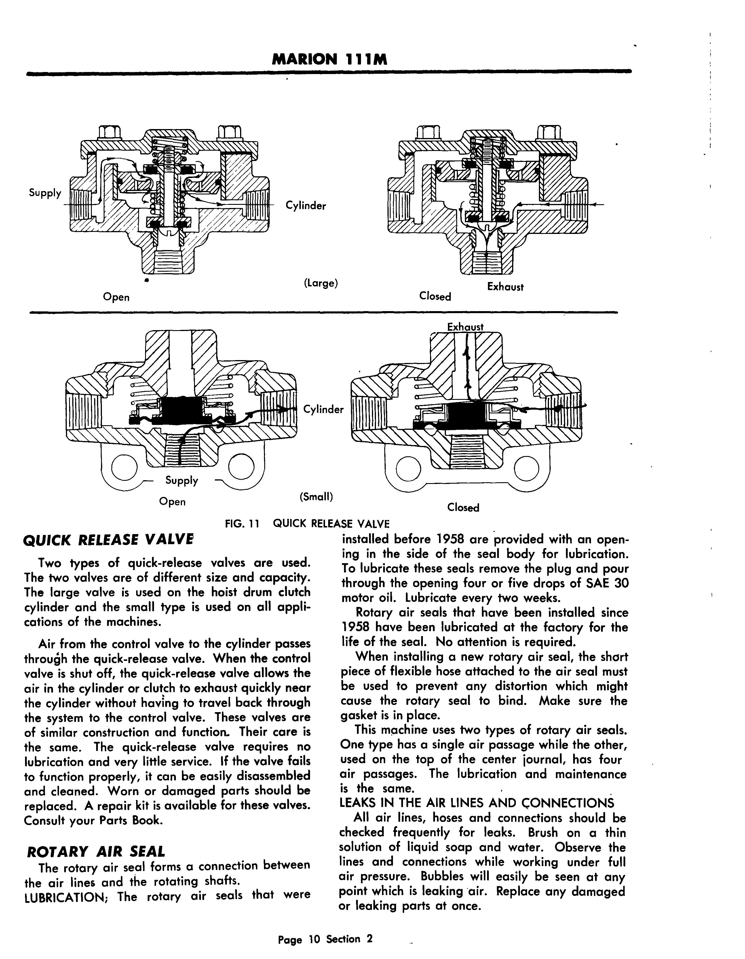
QUICK RELEASE VALVE
QUICK RELEASE VALVE
Two types of quick-release valves are used. The two valves are of different size and capacity. The large valve is used on the hoist drum clutch cylinder and the small type is used on all applications of the machines.
Air from the control valve to the cylinder passes through the quick-release valve. When the control valve is shut off, the quick-release valve allows the air in the cylinder or clutch to exhaust quickly near the cylinder without having to travel back through the system to the control valve. These valves are of similar construction and function.. Their care is the same. The quick-release valve requires no lubrication and very little service. If the valve fails to function properly, it can be easily disassembled and cleaned. Worn or damaged parts should be replaced. A repair kit is available for these valves. Consult your Parts Book.
ROTARY AIR SEAL
The rotary air seal forms a connection between the air lines and the rotating shafts.
LUBRICATION; The rotary air seals that were
installed before 1958 are ·provided with an opening in the side of the seal body for lubrication. To lubricate these seals remove the plug and pour through the opening four or five drops of SAE 30 motor oil. Lubricate every two weeks.
Rotary air seals that have been installed since 1958 have been lubricated at the factory for the life of the seal. No attention is required.
When installing a new rotary air seal, the short piece of flexible hose attached to the air seal must be used to prevent any distortion which might cause the rotary seal to bind. Make sure the gasket is in place.
This mpchine uses two types of rotary air seals. One type has a single air passage while the other, used on the top of the center journal, has four air passages. The lubrication and maintenance is the same.
LEAKS IN THE AIR LINES AND CONNECTIONS
All air lines, hoses and connections should be checked frequently for leaks. Brush on a thin solution of liquid soap and water. Observe the lines and connections while working under full air pressure. Bubbles will easily be seen at any point which is leaking air. Replace any damaged or leaking parts at once.
• Thank you very much for reading the preview of the manual.
• You can download the complete manual from: www.heydownloads.com by clicking the link below
• Please note: If there is no response to CLICKING the link, please download this PDF first and then click on it.
HOIST CLUTCH RELAY VALVE, FIG. 12
A relay valve, that is normally closed, is 10cQted at the left of the machinery frame near the tary air seal of the hoist drum shaft. The object of the relay valve is to reduce the volume of air that must pass through the compensating control
cylinder (0). When the air pressure in the cylinder exceeds that in the control line the cylinder pressure will move the piston down against the control sure until the application valve closes, and the sure on each side of the piston is in balance. The control pressure does not permit the piston to move down far enough to open the exhaust port.
valve and the long air lines between the control valve and the hoist clutch, and at the same time to make available a large volume of air to actuate the hoist drum clutch cylinder.
The relay is a valve that controls the air from the supply tank to the hoist clutch cylinder. The valve is 'held in closed position by tank pressure and is opened by a piston that is actuated by air pressure from the compensating control valve in such a way that the cylinder pressure' and the control pressure are in balance.
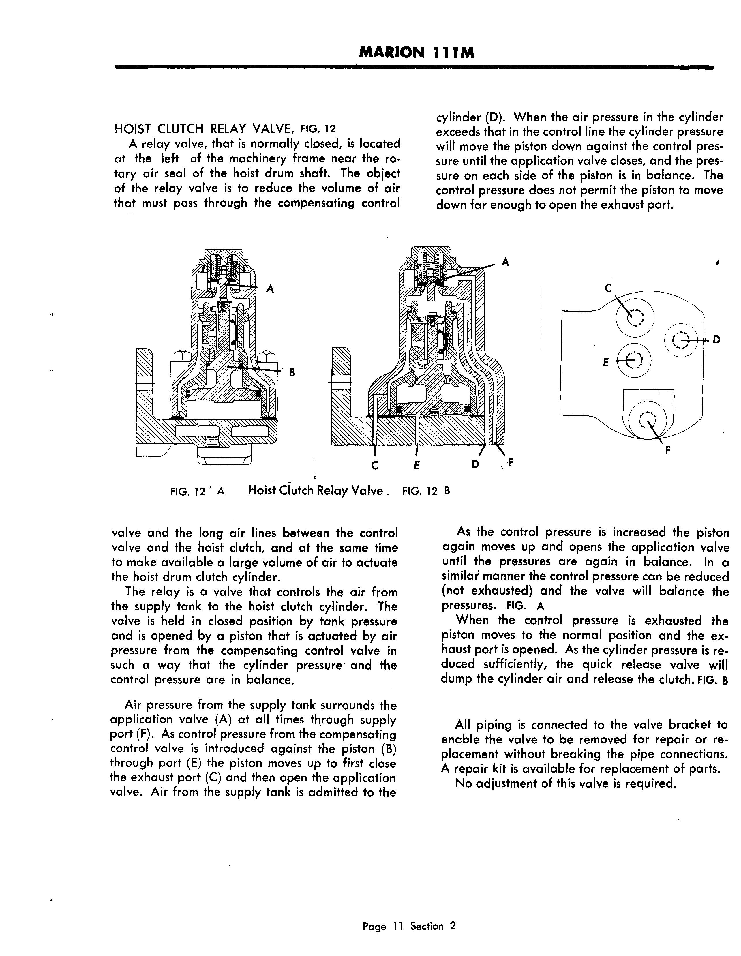
Air pressure from the supply tank surrounds the application valve (A) at all times th,rough supply port (F). As control pressure from the compensating control valve is introduced against the piston (B) through port (E) the piston moves up to first close the exhaust port (C) and then open the application valve. Air from the supply tank is admitted to the
As the control pressure is increased the piston again moves up and opens the application valve until the pressures are again in balance. In a similar manner the control pressure can be reduced (not exhausted) and the valve will balance the pressures. FIG. A
When the control pressure is exhausted the piston moves to the normal position and the haust port is opened. As the cylinder pressure is duced sufficiently, the quick release valve will dump the cylinder air and release the clutch. FIG. 8
All piping is connected to the valve bracket to enable the valve to be removed for repair or placement without breaking the pipe connections. A repair kit is available for replacement of parts. No adjustment of this valve is required.