
Technical Manual
• Thank you very much for reading the preview of the manual.
• You can download the complete manual from: www.heydownloads.com by clicking the link below
• Please note: If there is no response to CLICKING the link, please download this PDF first and then click on it.

INSTHTJCTTON MA.NU1U_.
MARION 5561
Manufactured By MARION POWER SHOVEL COMPANY
MARION, OHIO. U.S. A.


:~-.-. U.Ye been prep&"-' til··a4d ta. •r•~ • •~·-. ~-;, :.. ,:·.,~,~- . _ ve'l, amJ.-..-.-a:-auide for the operator,. the pouadmMl. and th•'iller· u.t the& · · operation;· lubri'cation.:and maintenance. The enpneering drawmg.a which accompany the t?U\chin~ give the exact location of all all.n:e-ce•aa:ry dimensions, etc •. It is very important that extreme care be taken in aa•embly be_cauae improper erection may cause unnecessary wear and faulty operation of the machine.
When the machine is shipped from the factory, the parts are match marked throughout. Care should be taken to follow these match marks when the machine is assembled.
All finished surfaces and bearings are protected against and should be thoroughly cleaned just before assembly. When assembling, all bearings should be lubr~.cated. Ball and roller bearings are to be filled only 1/2 full of the proper grease. Also lubricate all gears, and put the proper oil in gear cases up to the correct level befor~ the machine ii run. All air and electrical equipment, bearings and finished surfaces should be protected from the weather until the machine is fully assembled.
Select a level assembling area adjacent to the unloading point approximately 300' x 300' preferably made up of solid material and with good drainage. It may be advisable to place gravel or cinders in the immediate erection area.
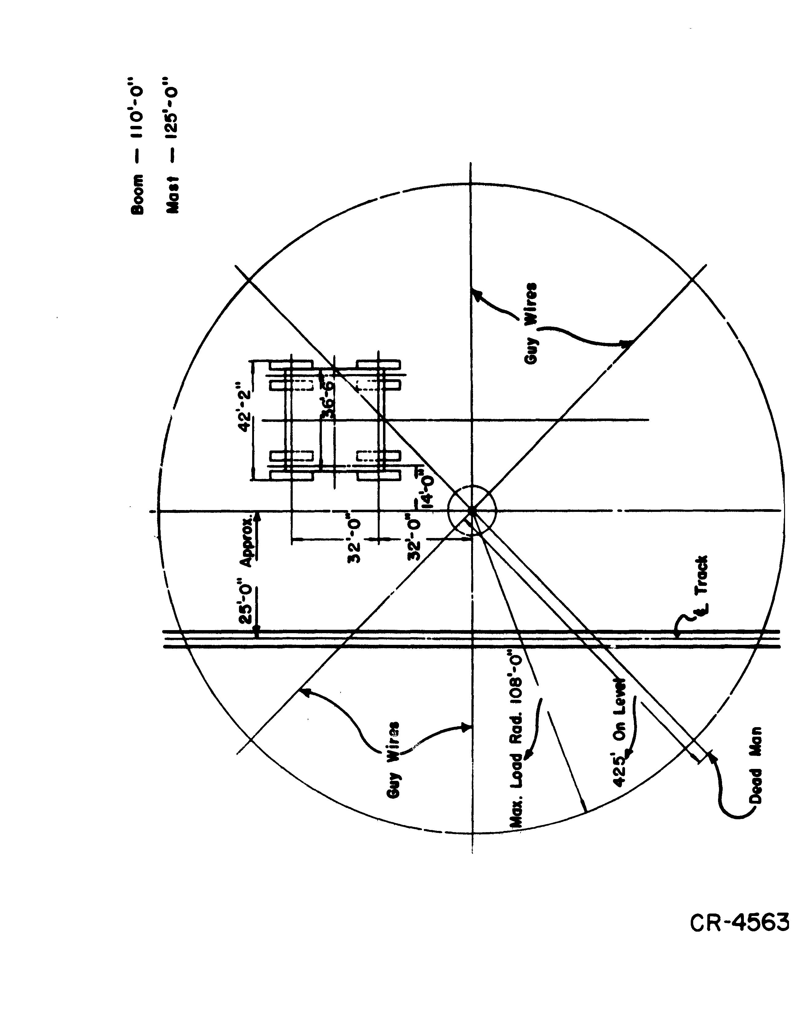
It is important that the derrick be placed so that the greatest loads can be lifted without interfering with the erection of the machine. The recommended position of this derrick is indicated on drawing CR-4563. If the ground is not level, place the dead men out further than the 425' indicated for boom clearance.

MATERIAL REQUIRED
Following is a list of materials required to aid in the erection of the macaine. They are to be furnished by the purchaser.
24 Z x 10 or 12" planks x 20' long
12 Z x 10 or 12" planks 10' to 12' long
90 Z x 10 or 12" planks 14' to 16' long
ZOO Z x 4 - 16' to 18' long
6 0 Z x 4 - 8' to 10 ' long
1000 standard railroad ties
6 16 x 16 x 21' posts
1000 hardwood wedges Z" thick, 15" long, 4" to
100.0 miscellaneous flat blocking Z"
lZ"
wide
8 dead men logs for anchoring derrick guys, ZO" diam. x 7' or 8 1 long, or can use 32 standard railroad ties.
It is recommended that a small tool room be erected at the erection site for the protection of the tools, drawings, etc.
It is -recommended that the following procedure be used in erecting the machine.

1. Accurately locate the centers of the crawlers and drive a stake into the ground at this point. Place __ r.ailroad ties around these stakes and level them with one another
Z. Place the four pairs of ciawlers in their exact on the ties. Assemble the truck axle to the crawlers and the steering sa4dle to the truck axle. Assemble the bumper. blocks on the steering saddle.
3. Make sure the crawlers are level with one another. Place cribbing under the long arm of the steering saddle and level.
4. Place the four pistons for equalizing cylinders in position, install all the bolts and plumb piston.
5. Place the V shaped plates on cylinders, letting them rest onthe bumper blocks.
f Assemble sections of lower frame.
a} Place the f_our structures on the equalizing cylinders, crib and level.
b) Place the front girder in pos1tion and bolt to the two front structures, crib and level.
c) Place right and left side girders in position and bolt to front and rear corner structures, and level.
d) Place on the ground, in their approximate positions, the main propel bracket and the steering brackets.
e) Place the two parallel beams in position, bolt to front girder, crib and level.
f) Starting at the front and working to the rear, install the diagonal short beams in position, bolting to outside girders and parallel beams.
g) Place rear girder in posHion and bolt to rear corner structures, also bolt diagonal beams to this girder.
h) Place bottom plate under center journal, and install all side plates.
i) Complete bolting and riveti:q.g the lower frame.
j) Recheck the level of the frame.
7. Install all ladders, stairs,, platforms, handrails and walkways.
8. Install cable reel assembly on rear of frame.
9. Install oil tanks and all piping for the equalizing cylinders, oil pumps, hydraulic panels and any other electrical equipment that can be installed. Note: Electrical and hydraulic equipment to be installed in coordination with the assembly of the mechanical equipment.
10. Install the intermediate steering shaft brackets.
11. Install the cross propel shaft brackets.
12. Install the main propel shaft bearing bracket.
l3. Install the two speed propel spafts and the parallel propel shafts in their brackets.
14. Install the telescopic propel shafts.
15. Install ti··' .;tP('ring screw shafts.
'
7. As setnbL: · :··
th:-1t all nuts are tight on all bearing brackets and bearing _1.· the nuts on cross prr;pd shaft knuckles and steering : l :ci.< brak(' dw<:;;s, u:::ver::, and ram cylinders.
18. of an hydraulic equipment, electrical equipment, and lim1t sw1tc11es for equalizing cylinders in lower frame.
19. Place center journal m position and jnstall slip rings, Install collector rings at bottom oi center journal.

Place all cover plates in position on top of frame.
21.
Place main swing gear segments into position, but do not bolt down until all segments are in their exact position. After this is accomplished, bolt all segments securely.
22. the four sections of the inside rail circle in position, but do not bot!. down until all the sections are in their exac;t location. After this is ai bolt all sections securely.
r,lace the four sections of the outside .raiL circle in position but do not bc1H down until all the. sections are in their exact location. After this is
bolt all sections securely .
Note: Operations 19, 20, 21, 22 and 23 can be done simultaneously with other operations of erection; but not until the frame ha• been completed.
Assemble the upper frame roller circle and place on lower frame roller circle track.
Assemble the upper frame.
a) Level lower frame by using the hydraulic jacks. Place the rail circle sections in position on their roller circle.
b) Locate and place any additional blocking which might be needed in supporting the upper frame during its assembly.
c) Refer to upper frame erecting prints, noting the welding and assembly procedure as given on them, before proceeding with the assembly of the frame. Be sure to incorporate and carry out these instructions in their proper sequence during the following procedure.

d) Place bottom plates of upper frame in their proper location on the rail circle.
e) Place bottom flange plates and bottom reinforcing plates in position.
f) Place center journal weldment over the center journal, keeping in mind that the inside longitudinal girder flanges have to fit underneath the center journal weldment.
g) Place in.position the two outside sections of the upper frame, which includes the inside longitudinal, the intermediate longitudinal and outside longitudinal girders.
h) Build up cribbing to support rear center section of upper frame. Place rear section of upper frame in position.
i) Place the front girder section in position.
j) Place the wing sections in position.
k) Be sure that the welding and assembly procedure given on the upper frame erecting prints) pertaining to the assembly so far has been completed.
f) Place top flange plates and reinforcing plates in position.
m) Place top plates in position.
n) Check again and be sure that the remainder of the welding and assembly procedure has been completed.
26. After upper frame has been completely as sembled, the following procedure can be used to obtain more working room between the lower frame and upper frame.
a) Rotate the upper frame·by using block and tackle, erection crane or by any other means; so that the center line of the upper frame through the center line of hydraulic jack.
b) Pump the lower frame up, then pi.ac(' support posts under the upper frame.
c) Lower the lower frame back down on the bumper blocks.
d) It may be advisable to put cribbing or additional blocking the upper fran1e to insure a good safety factor of protection for men working b('tween the two frames.
27. c('mp1vtt.' \'(· tv c:. i:i'1.d welding of the upper frame sections together from ·f "2' f' .t1f',,j: 1"'.!
28. Afte.;.· the work on underside o:( upper frame is completed, pump lower frame up Lmlil there is approximately 40" clearance. At this time, boll the upper frar..:.c rail circle to the bottom of the upper frame. After this is complctt'd, pump the lower frame up so that the upper frame rests on the lower frame remove support posts.
29. R')tate Ul';'· 1· fr:cur,(: back $0 that its center line coincides with center line of tower frar:lE..
30. Lower the lower frame and upper frame assembly until the upper frame's rear portion rests on the cribbing.
31. Install ballast as indicated in L. P. 241. Ballast shouid be distributed 1n accordance with these instructions so t:hat the machine will be properly balanced when in operation. During this operation, care should be excerised so t.h,:tt the electrical equipment is not damaged. Note: Consult Marion Power Shovel Company for any variation from the standard ballast.

32. Install MG set.
33. Place all machinery on upper including electrical equipment and necessary wiring. Be sure that all the machinery is covered and protected from the weather (For setting th,e hoist machinery, see operation 47 and L. P.
3.4. Ins;all ali g:::.ards and handrails on upper frame.
3 Assemble and install gantry and fittings including motor platform, crowd rnotors, shipper shaft, wterrnediate crowd shafts, deflecting sheaves, all guards, walkways, handrails. ladde:rs and jib crane.

Caution: Machine is shipped less fluid lubricant in gear cases. Be sure that they are filled.
Remove all cribbing.
After painting is completed, the machine is now ready for testing and making electrical settings.
48. Setting of the Hoist Machinery (See L. P. 233).

In setting up the hoist machinery, observe the following procedure.
These adjustments are for the front hoist motor extension shaft. For the rear hoist motor extension shaft, follow the same procedure except shift the hoist drum shaft to the left.
1. Setting proper gap between coupling faces.
a) There is 1/16" clearance between the width of the hoist drum shaft assembly and the width between the inside faces of the machinery base bearings.
b) The maximum float or end play of the hoist motor armature can be 1/4''.
c) Shift the hoist drum shaft endways (to the right) in the direction of the coupling on the hoist motor extension shaft. Therefore, all the clearance between the hoist drum shaft assembly and hoist machinery base will be eliminated in this particular direction. The hoist motor extension shaft will,. of course, move over with the hoist drum
d) Shift the armature shaft towards the coupling so that all end play will be eliminated in this particular direction.
e) Allow 1/8" gap between the faces of the coupling after procedures (c) and (d) have been completed.
f) Thus a minimum gap of 1/8, a normal gap of 9/32 or maximum gap of 7/16 could exist in the coupling. According to Falk specifications the allowable minimum gap is 1/16", the normal gap is 1/4" and the allowable maximum gap is 1/2".
g) Therefore, this above procedure permits a 1/16" increase in end play in either direction on hoist drum shaft assembly due to wear.
2. Setting for proper back lash and gear centers. (L. P. 233).
a) Obtain from the Engineering Department the dimensions A, B, C, D, E, H, J and K for the particular machine being erected.
b) The back lash setting between the hoist gear teeth and the hoist motor extension shaft pinion teeth should be between 012" to
36. Assemble operator's control station on front of upper frame. Install and connect the hoist, swing and crowd controllers, and operator's control box. Make all connections.
37. Install house on upper frame. ways, handrails and guards. side.
Install all floodlights, all remaining wal Also install crane on outside of house, L. H.
38. The boom assembly can be a simultaneous operation with the assembling of the upper frame. Assemble the boom, including installation of all boom fittings, point sheaves, ladder and handrail, structure at point of boom, and the jib crane on boom.
39. Raise boom to operating position and install all support cables. (See L. P. 227 and L. P. 327 in Section IV).
SUGGESTIONS FOR RAISING BOOM
l) Set hoist brake up very tight and adjust same to hold boom in any position. Disconnect hoist brake magnet valve electrically and manually operate, while boom is being raised. By this method, the brake can be easily set while the boom is being raised with power, thus avoiding any drift when power is removed.
2) Securely lash the "Bull" or main drive gear to hoist drum spokes, first placing a spacer plate between drum spoke and gear spoke. From 10 to 15 tltrns of 1/2" or 5/8" wire rope can be used to lash dt"um and gear together. Air should be applied to air ram cylinder to set friction.
3) In addition to the foregoing, a railroad tie cut to the proper length to set between friction "dead" end anchor pin boss and the deck to assure that the drum and gear assembly cannot rotate until the boom cables are secured to gantry.
40. Place stiff leg and crowd handles in position. Install crowd limit switches.
41. Assemble handle to dipper. Place dipper on set of railroad ties so it won't roll sideways when raised.
42. Lift handle with derrick and connect to universal joint.
43. A.ssemble bail and sheave block.
44. Reeve hoist cable. (See L. P. 220, Section IV).
45. all adjustments and completely recheck the machine for any loose bolts, nuts, cotters or errors in assembly. Remove all tools and equip ment. Check all moving parts for obstructions which may cause dama
46. Install the proper type and amount of oil in all gear cases, hydraulic system, etc. Completely lubricate the machine with type of lubricant recommended in Lubrication Section.
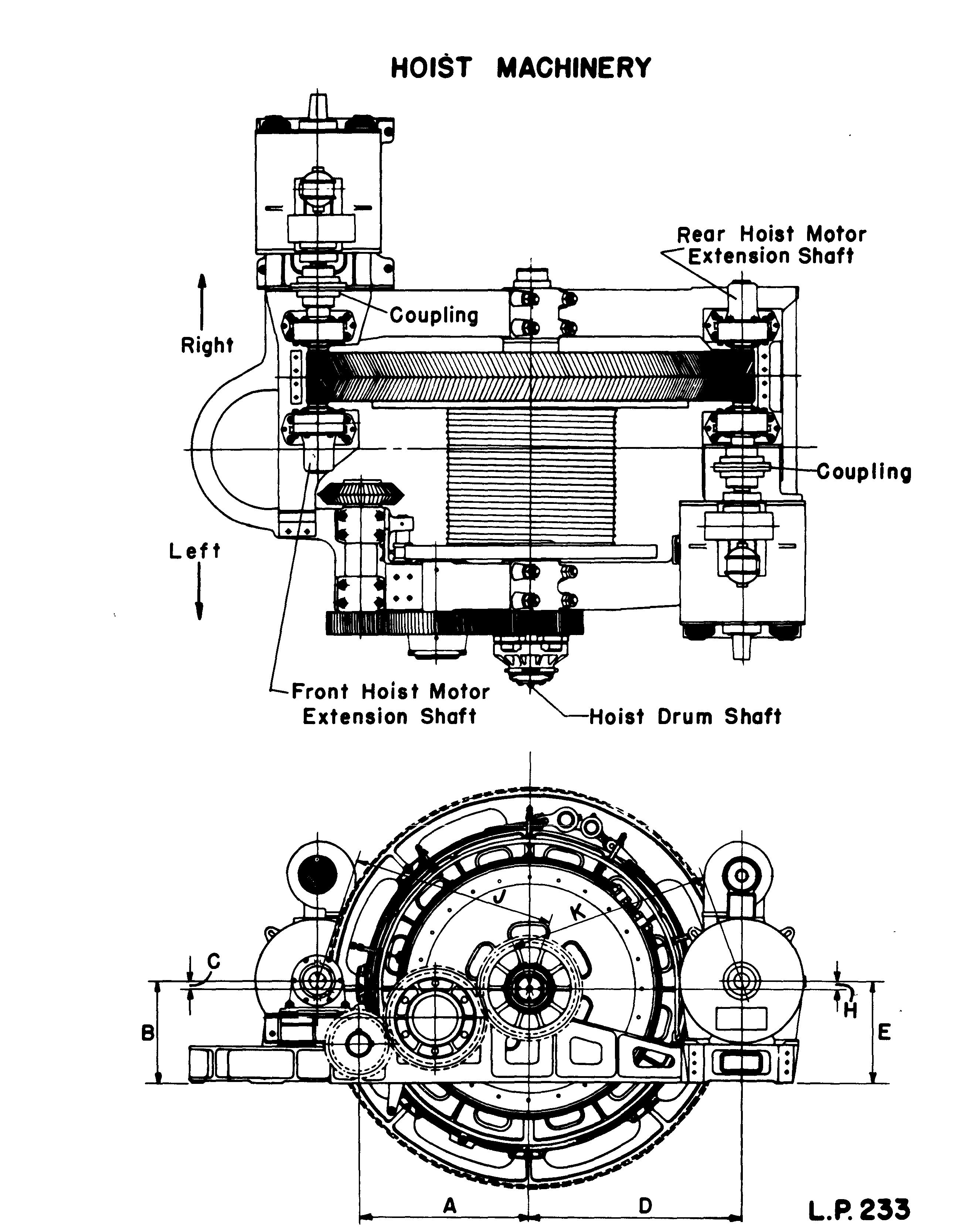
c) The clearance between the outside diameter of gear and root diameter of pinion or the root diameter of gear and outside diameter of pinion is 0 12".
3. After the. machine i-s completely assembled and ready to operate, the above settings should be checked thoroughly.
4. Drill and ream dowel holes for hoist motor extension shaft bearings and insert dowels.
5. Babbit in place the feet of hoist motors in their final location.
SECTION 11


