
Technical Manual
• Thank you very much for reading the preview of the manual.
• You can download the complete manual from: www.heydownloads.com by clicking the link below
• Please note: If there is no response to CLICKING the link, please download this PDF first and then click on it.


Genercd Information
Air Control
Lower Frame
Upper frame
Front End
Operating Instructions
Erecting Instructions
TABLE OF CONTENTS
•
Section 1
Section 2
Section 3
Section 4
Section 5
Section 6
Section 7
SECTION 1
GENERAL INFORMATION
INTRODUCTION
This manual is provided for the guidance of all persons who operate, lubricate, adjust or maintain the Marion 5323 stripping shovel. The information was prepared. with the purpose in mind of furnishing accurately and concisely all the data necessary to the operation and servicing of this machine.
All information, measurements and specifications herein are in accord with the Marion Power Shovel Engineering Department and should be strictly adhered to in all work on this machine.
PARTS BOOKS
THIS MANUAL IS NOT A PARTS BOOK AND SHOULD NOT BE USED IN ORDERING PARTS. You have been furnished detailed Parts Books which list all parts by group numbers, with item and parts numbers for your specific machine.
· When ordering parts, it is necessary that all the following information accompany each order:
Type
Serial 'Number
Group Number Description
Part Number
Item Number
SERIAL NUMBER OF MACHINE
Be sure that the serial number of the machine is given in any letters, telegrams, orders or other communications. Records for each individual machine are filled by serial number and if this number is available, the design ancl original equipment can be quickly ancl accurately checked.
The serial number of the machine will be found on a name plate inside the cab.
RIGHT AND LEFT HAND PARTS
On the upper frame, right hand (r.h.) and left hand (l.h.) correspond to the operator's right and left hands when he is facing forward. On the lower frame, standing at the rear or facing the power cable reel, right hand and left hand correspond to your own right and left hands.
ORDERING PARTS
The Parts Book covering this machine gives complete information on how to order parts. Order carefully so that the right parts in the right quantities can be furnished. Wrong parts, ordered by mistake, which are returned to the Company are subject to a rehandling charge.
FURTHER INFORMATION
If further information is required which is not found in this Manual or in the Parts Books, communicate with the Marion Power Shovel Company at Marion, Ohio.
CHARGES FOR SERVICE, LABOR, ETC.
No charges for service or labor are accepted unless the work has been previously authorized by the company in writing.
STANDARD WARRANTY
MARION POWER SHOVEL COMPANY guarantees the parts manufactured by it to be free from defects in material and workmanship under normal use and service, its obligation under this warranty being limited to making good at its factory any part or parts thereof manufactured by it which shall, within ninety days after delivery of said machine to the original purchaser, be returnecl to it with transportation charges prepaid, and which its examination shall disclose to its satisfaction to have been thus defective; this warranty being expressly in lieu of all other warranties expressed or implied, and of all other obligations or liabilities on MARION POWER SHOVEL COMPANY'S part.
SAFETY PRECAUTIONS
The usefulness of this machine depends entirely on the man at the controls. The operator is its brains. HE MUST THINK SAFETY AND WORK SAFELY.
Neatness and safety go hand in hand. Good housekeeping habits should be developed.
1. Keep the floor clean and free from oil and grease.
2. Keep the walkways clean, clear and free from obstructions.
3. Prevent the accumulation of grease and oil around bearings and gears. Grease and oil collect and hold grit and dirt which work into finely machined parts.
4. A clean machine is· easier to operate-easier to inspect-easier to service.
5. Keep hands and clothing away from moving parts.
Strip mining equipment is subject to tremendous stresses and shock loads. These stresses are thoroughly studied and considered in the design and building of Marion equipment.
This machine is built with an ample reserve of power and strength and is well fitted to meet the demands of its task.
However, the Marion engineers cannot foresee the conditions imposed by abuse, mismanagement and neglect. These factors are more damaging to any piece of equipment than years of continuous operation and normal wear.
Care, sound judgment and reason are an economic necessity in the operation of power equipment.
Do-
A LITTLE PRIDE PAYS OFF-----------
1. Carefully read this Manual and Parts Books.
2. Lubricate regularly. Establish a systematic procedure and stick to it.
3. When lubricating, check all bolts, nuts, locknuts · and cotter pins.
4. Keep loose objects in tool box or in suitable enclosure or cabinet.
5. Always replace guards.
6. Always watch your cleqrances when swinging.
Don't-
1. Service or lubricate parts that are moving.
2. Leave the load suspended in air.
DON'T APPLY SWING BRAKES WHILE MACHINE IS ROTATING, EXCEPT IN E.MERGENCY.
SECTION 2
AIR CONTROL
Air System
Air Compressor
Air Cleaner
Air Receiver (Tank)
Anti-freezer
Crowd Friction Regulator Valve
Quick Release Valve
Rotary Air Seal
Solenoid Valves (Magnet Valves)
Page 3
Page 3
Page3
Page 3
Page4
Page4
PageS
Page 5
Page 6
AIR SYSTEM
A-Air Compressor and Air Cleaner
B-Storage Tank
C-Anti-Freezer
D-Sediment Collector
E-Hose Connector and Valve
F-Salenoid Valve (Normally closed)
G-Salenaid Valve (Normally open)
H-Quick Release Valve
J-Rotary Air Seal
!<-Hoist Clutch Cylinder
L-Rotatinq Brake Cylinder
M-Hoist Brake Cylinder
N-Propel Clutch Cylinder
P-Giobe Valve
Q-Whistle
R-Air Pressure Gauge
5--Pressure Regulator
T-Crowd Brake Cylinder
U-Drain Petcock
V-Pressure Switch

AIR SYSTEM
The operating controls of the 5323 stripping shovel upper frame machinery are actuated by compressed air, The compressed air is controlled by electric solenoid valves.
The Marion air control system is simple in operation and with reasonable care and maintenance it will have a long and trouble-free service life.
The system can best be explained by a brief description of its components and their functions in the system. Fig. 1 shows a schematic view of the complete system used on this machine.
The operator must be constantly aware of the air pressure gauge reading. If at any time the air pressure drops below the minimum operating pressure differential (90 psi) the operator should shut down the machine and investigate.
DO NOT OPERATE THE MACHINE WITHOUT FULL TANK PRESSURE. If the proper air pressure is not maintained, check the following:
1. Air compressor for proper operation
2. Pressure switch for proper adjustment and operation
3. "V" belt drive for proper adjustment and condition of belts
4. Air intake for obstruction or dirty air cleaner
5. Leaks in air lines or components
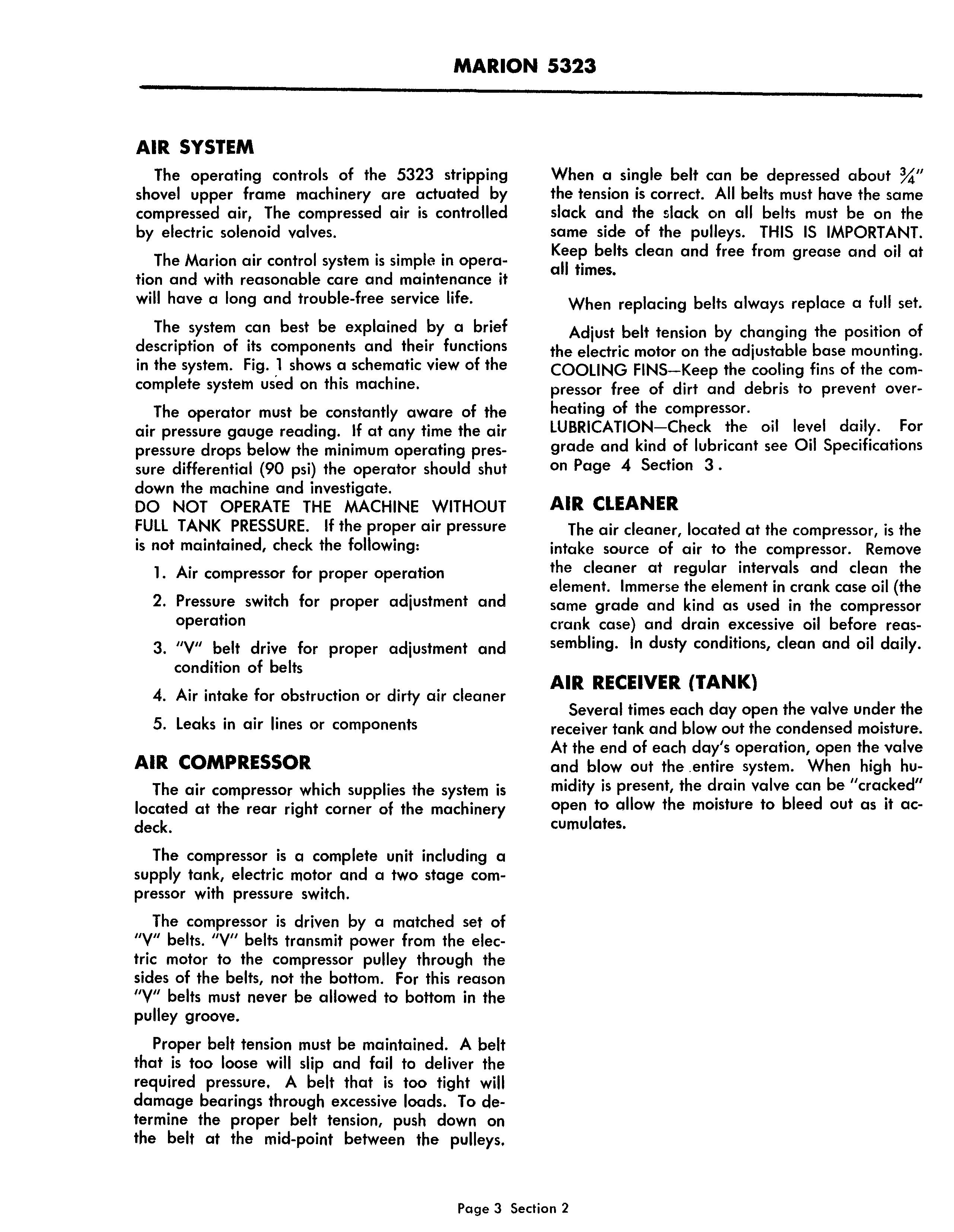
AIR COMPRESSOR
The air compressor which supplies the system is located at the rear right corner of the machinery deck.
The compressor is a complete unit including a supply tank, electric motor and a two stage compressor with pressure switch.
The compressor is driven by a matched set of "V" belts. "V" belts transmit power from the electric motor to the compressor pulley through the sides of the belts, not the bottom. For this reason oyu belts must never be allowed to bottom in the pulley groove.
Proper belt tension must be maintained. A belt that is too loose will slip and fail to deliver the required pressure. A belt that is too tight will damage bearings through excessive loads. To determine the proper belt tension, push down on the belt at the mid-point between the pulleys.
When a single belt can be depressed about %" the tension is correct. All belts must have the same slack and the slack on all belts must be on the same side of the pulleys. THIS IS IMPORTANT. Keep belts clean and free from grease and oil at all times.
When replacing belts always replace a full set. Adjust belt tension by changing the position of the electric motor on the adjustable base mounting.
COOLING FINS-Keep the cooling fins of the compressor free of dirt and debris to prevent overheating of the compressor.
LUBRICATION-Check the oil level daily. For grade and kind of lubricant see Oil Specifications on Page 4 Section 3 .
AIR CLEANER
The air cleaner, located at the compressor, is the intake source of air to the compressor. Remove the cleaner at regular intervals and clean the element. Immerse the element in crank case oil (the same grade and kind as used in the compressor crank case) and drain excessive oil before reassembling. In dusty conditions, clean and oil daily.
AIR RECEIVER (TANK)
Several times each day open the valve under the receiver tank and blow out the condensed moisture. At the end of each day's operation, open the valve and blow out the .entire system. When high humidity is present, the drain valve can be "cracked" open to allow the moisture to bleed out as it accumulates.
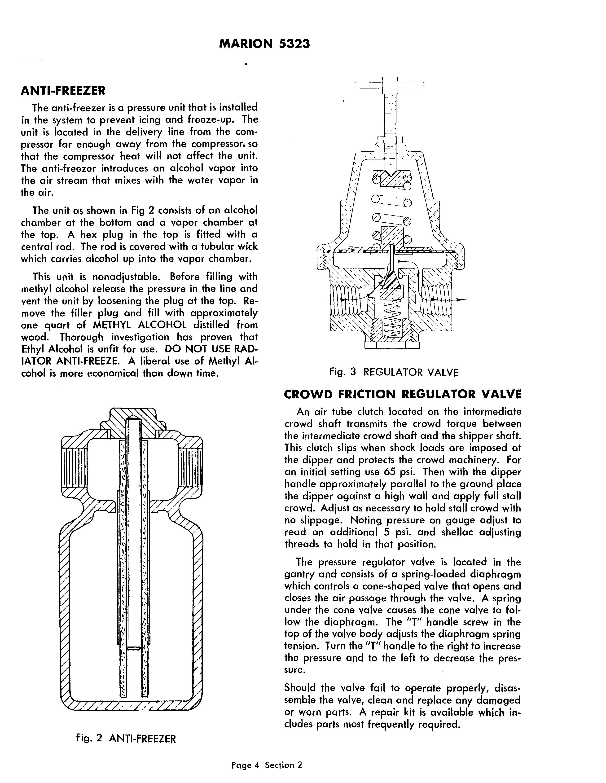
ANTI-FREEZER
The anti-freezer is a pressure unit that is installed in the system to prevent icing and freeze-up. The unit is located in the delivery line from the compressor far enough away from the compressor. so that the compressor heat will not affect the unit. The anti-freezer introduces an alcohol vapor into the air stream that mixes with the water vapor in the air.
The unit as shown in Fig 2 consists of an alcohol chamber at the bottom and a vapor chamber at the top. A hex plug in the top is fitted with a central rod. The rod is covered with a tubular wick which carries alcohol up into the vapor chamber.
This unit is nonadjustable. Before filling with methyl alcohol release the pressure in the line and vent the unit by loosening the plug at the top. Remove the filler plug and fill with approximately one quart of METHYL ALCOHOL distilled from wood. Thorough investigation has proven that Ethyl Alcohol is unfit for use. DO NOT USE RADIATOR ANTI-FREEZE. A liberal use of Methyl Alcohol is more economical than down time.
CROWD FRICTION REGULATOR VALVE
An air tube clutch located on the intermediate crowd shaft transmits the crowd torque between the intermediate crowd shaft and the shipper shaft. This clutch slips when shock loads are imposed at the dipper and protects the crowd machinery. For an initial setting use 65 psi. Then with the dipper handle approximately parallel to the ground place the dipper against a high wall and apply full stall crowd. Adjust as necessary to hold stall crowd with no slippage. Noting pressure on gauge adjust to read an additional 5 psi. and shellac adjusting threads to hold in that position.
The pressure regulator valve is located in the gantry and consists of a spring-loaded diaphragm which controls a cone-shaped valve that opens and closes the air passage through the valve. A spring under the cone valve causes the cone valve to follow the diaphragm. The "T" handle screw in the top of the valve body adjusts the diaphragm spring tension. Turn the "T" handle to the right to increase the pressure and to the left to decrease the pressure.
Should the valve fail to operate properly, disassemble the valve, clean and replace any damaged or worn parts. A repair kit is available which includes parts most frequently required.
MARION 5323
QUICK RELEASE VALVE
The quick release valve is located in the air line near the brake cylinders. Air that is introduced into the cylinder must pass through the quick release valve. The air first depresses the diaphragm causing the valve to close the exhaust port and open the valve seat to admit pressure directly to the cylinder. Full tank pressure will pass through the valve without restriction. When the supply pressure is shut off, the diaphragm spring will return the diaphragm to normal position and the exhaust port will open. This permits the pressure inside the cylinder to escape into the atmosphere and not be required to return to the control valve. No adjustment is required of this valve. If the valve fails to function properly, the valve should be disassembled, cleaned and inspected for damaged parts. A repair kit is available which contains the parts most frequently required for replacement. (Refer to Ports Book.)

ROTARY AIR SEAL
The rotary air seal forms a connection between the air lines and rotating shafts*. The rotary seals ore lubricated at the factory for the life of the seed. No attention is required.
When installing a new rotary air seal, the short piece of flexible hose attached to the seal must be used to prevent any distortion which might cause the seal to bind. Make sure the gasket is in place.
*Intermediate crowd shaft and .hoist drum shaft.
Fig. 4 QUICK RELEASE VALVESOLENOID VALVES (MAGNET VALVES)
The solenoid or magnet valves are electrically controlled air valves. These valves are noncompensating or on and off valves. Both normally open and normally closed valves are installed ·on this machine.
The valve which is normally open (Hoist Clutch) when de-energized will admit the air pressure from the supply into the cylinder. When the coil is energized the plunger moves down and closes the supply and opens the exhaust port from the cylinder the atmosphere.

The valves (all others) which are normally closed when the coil is de-energized will shut off the air from the supply to the cylinder and will open the exhaust from the cylinder to the atmosphere.
When the coil is energized the plunger moves down and closes the exhaust and opens the port from the supply to the cylinder.
Magnet valves are rugged and require little or no attention.
If the valve fails to admit the proper volume of air the valve should be cleaned as dirt and scale can cause the valve to leak.
Open and close the valve several times, by means of the hand lever on top of the valve, with full tank pressure. The valve can usually be cleaned this way without disassembling the valve. If not, dismantle the valve and clean or replace worn or damaged parts.
Apply a good grade of zinc base waterproof grease very sparingly to all parts before assembly.
Power Flow
SECTION 3 LOWER FRAME
lubrication of Anti-friction Bearings
Lubrication of Gears
Lubrication Fittings
Selection of Lubricants
Lubrication Specifications
Lubrication Code
LUBRICATION OF:
Crawler Unit
Cross Propel and Telescopic Propel Shafts
Propel Shafts
Propel Brakes
Steering Mechanism
Equalizer Cylinder
Cable Reel
Crawler Tread Belt
Torque limit Coupling
Parallel Propel Shaft
Propel Gear Shifter Cylinder
Hydraulic System for Propel Brakes and Two-Speed Propel Shifter
Propel Brake
Propel Brake Ram Cylinder
To Install and Adjust the Steering Mechanism
Automatic leveling Device
Hydraulic leveling Cylinder
Power Cable Reel
8
11
14 Page 16
23
25
7 Page9 Page 11 Page 11 Page 13 Page 15 Page 15 Page 17

Page 19
Page 22
Page25
Propel Broke Housing
Parallel Propel Shaft (Long)
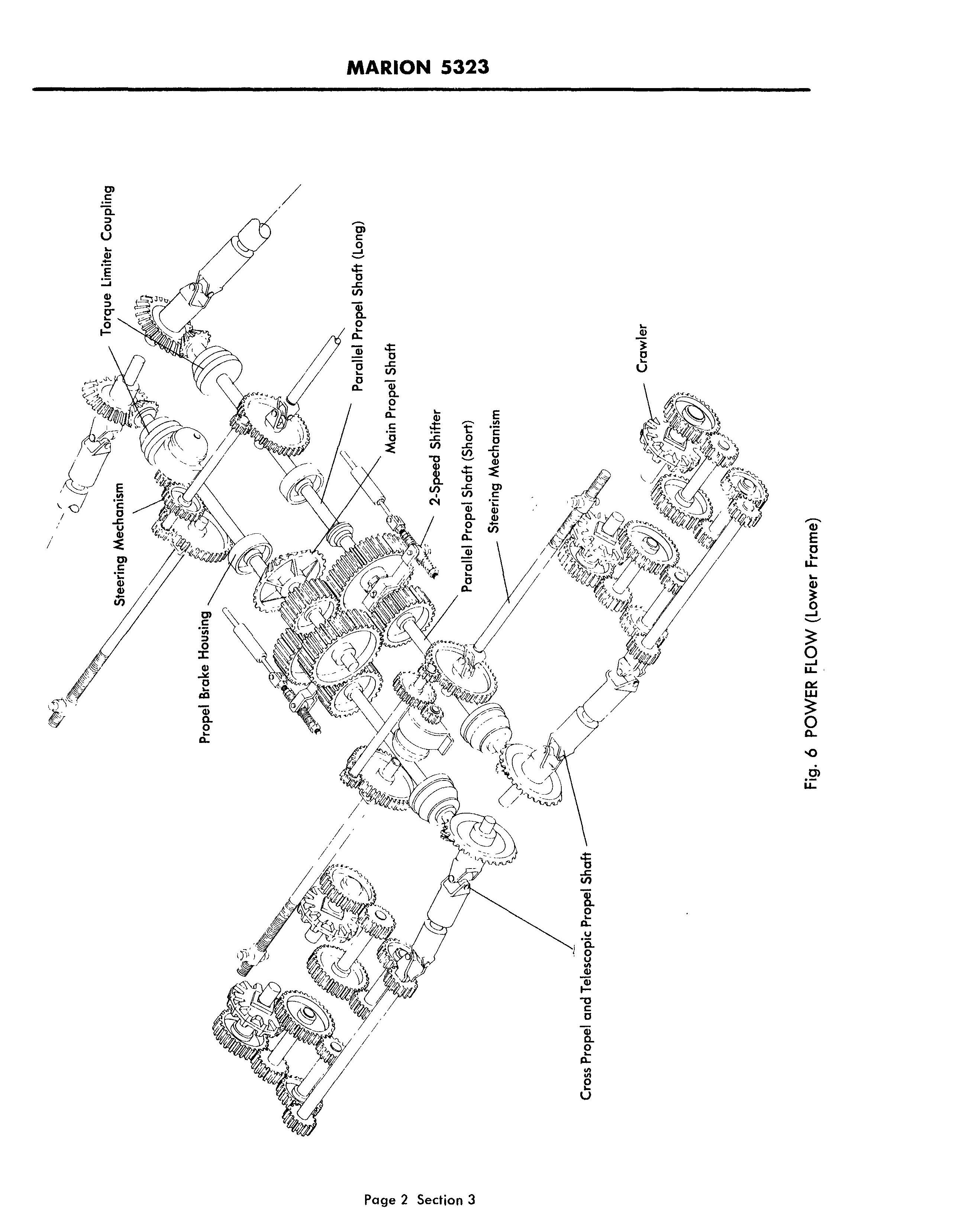
Main Propel Shaft
2-Speed Shifter
Crawler
Cross Propel and Telescopic Propel Shaft
POWER FLOW (Lower Frame)
LUBRICATION OF ANTI-FRICTION BEARINGS
All roller and ball bearings on the machine should be kept about % to V2 full of the lubricant recommended in the Lubrication Instructions. Add only enough lubricant to maintain this level. These are oil-tight bearings and the lubricant level will usually remain constant over a long period of time. Therefore, only very small quantities need be added. Unless otherwise specified, we recommend a small amount of lubricant every 500 hours which will usually maintain the desired level in the bearing of about % to % full at all times.
If these bearings should ever become completely filled, the addition of more lubricant would result in pressure being built up inside the bearing and heating would result. If a bearing should run excessively warm, it is advisable to remove the pressure fittings and allow some of the excess lubricant to escape.
LUBRICATION OF GEARS (Open or Semi-enclosed)

It is important to make sure every rotating or movable part is properly lubricated. The pinions and gears on hoist and crowd machinery, as well as racking on the dipper handle, and on all other gears and pinions which are not enclosed should also be kept coated with a good grade of gear lubricant as recommended in Lubrication Instructions. Oil should be kept at the proper level in all en· closed gear cases.
LUBRICATION FITTINGS
This machine is fitted with two types of lubrication fittings. The button head fitting for plain or bronze bushed bearings and hydraulic push-on fittings for anti-friction bearings. This way the operator can easily distinguish between anti-friction and plain bearings if he wishes to use different kinds of lubricant or to determine the frequency of lubrication.
SELECTION OF LUBRICANTS
No part of the care of your Marion machine is more important than proper lubrication. WITHOUT PROPER LUBRICATION, the air compressor, antifriction bearings, finished shafts, gears and other important parts of this precision-built piece of machinery can be quickly ruined.
For this reason, the lubricants recommended for this machine have been selected according to the ASTM specification standards. These standards have been compiled through the cooperation of major petroleum suppliers in order that the consumer can be supplied with the exact lubricant to fit specific requirements regardless of the source of supply.
We recommend that the following information be made available to your petroleum supplier to assist him in selecting the proper product for each application on your machine.
Penetration Worked 60 Str. 77°
Summer NLGI # Winter NLGI #
Penetration worked 5000 Str. Max. Change
Dropping Point Min.-Deg.
Vis: @


