
Technical Manual
• Thank you very much for reading the preview of the manual.
• You can download the complete manual from: www.heydownloads.com by clicking the link below
• Please note: If there is no response to CLICKING the link, please download this PDF first and then click on it.

APPENDIX A- SWING RECORDER


SECTION I
INTRODUCTION
GENERAL INFORMATION
This manual is designed to assist the owner in the operation and preventive maintenance of this machine. Following easy to understand step-by-step procedures, maintenance personnel can perform these tasks in a safe manner. When a systematic and thorough maintenance/service procedure (a responsibility of the maintenance superintendent) is used for this machine, minimum unplanned downtime and reliable operation will result.

THIS MANUALS IS NOT THE PARTS BOOK, and cannot be used to order parts. A separate, detailed parts book has been supplied. Please carefully read the instructions in it. All parts are listed by group and/or product code numbers with item/part numbers for THIS SPECIFIC MACHINE. Order parts in quantity. Parts ordered by mistake and returned, are subject to a rehandling charge. RIGHT and LEFT HAND PARTS on the upper frame correspond to the operator's hands at the controls; as seated when operating the machine. Please state the correct machine SERIAL NUMBER (located on a plate in the operator's cab) when corresponding or contacting factory service or parts departments. Records on each machine are filed by serial number and when given this number, your machine's specific design and original equipment is accessed quickly by the Dresser parts representative.
Periodic additions or revisions may be made to this manual. These will be mailed direct to you from the factory. Should you require additional information or factory service assistance contact your regional service representative or
Service Department
Dresser Industries, Inc.
Marion Division
617 West Center Street
P.O. Box 505 Marion, OH 43302
Telephone 614/383-5211
Telex 24-5307
Telecopier 614/383-5211
It is Dresser's policy to improve its products whenever possible and practical to do so. The company reserves the right to make changes or add improvements at any time without incurring any obligation to install such changes on machines sold previously.
Due to this continuous program of product research and development some procedures, specifications and parts may be altered in a constant effort to improve machines.
SAFETY PRECAUTIONS
This safety alert symbol is used hereand throughout this manual to call your attention to instructions concerning your personal safety. Carefully read and follow these instructions and observe all SAFETY, DANGER, and CAUTION graphics mounted on various areas of the machine.

Be certain anyone servicing this machine is aware of these SAFETY PRECAUTIONS. In the event you question your ability to safely perform any of the enclosed maintenance and operational procedures contact your regional Dresser service representative or the Service Department here in Marion.
The following defines distinctions between safety instructions. In all these definitions the safety alert signal is used.
DANGER: extreme intrinsic hazard which exists and could result in high probability of death or irreparable injury if proper precautions are ignored.
ACAUTION: a reminder of safety practices or directs attention to unsafe practices which could result in personal injury if proper precautions are ignored.
An example of a safety alert symbol and special safety instruction is shown below.
ADANGER: Inherent danger exists in the operation of any high voltage electrical equipment. A safe grounding system includes ground conductors in the power cable, a neutral grounding resistor, and related relays and switchgear. A ground continuity check system is required by law in many parts of the world.
Operating, maintaining or servicing this machine can be dangerous unless performed properly. The personnel involved with the operation and maintenance of this machine must be properly trained, and demonstrate to their superiors that they can safely perform their duties. Factory service representatives and specialists are available to provide additional information or technical assistance.
The operator must be alert, physically fit, and free from the influence of alcohol, drugs, or medications that might affect his eyesight, hearing or reactions.
Safety must always be the operator's most important concern. He must consult his supervisor when safety is in doubt.
SAFETY PRECAUTIONS· continued
The owner and/or operator must replace any and all safety and warning product graphics if they are defaced or removed from the machine.
Before doing any work on the machine, lock out or remove electric power supply from the machine and tag it so personnel are aware that someone is working on the machine.
Do not start an engine indoors unless adequate exhaust ventilators are provided. Once an engine is running, move the machine outdoors as soon as possible.
Keep hands, feet, clothing away from rotating parts.
As a machine is being moved, the operator should face the direction of travel.
Think before you act. Carelessness is one luxury the service man cannot afford.
Do not wear rings, wrist watches or loose fitting .clothing when working on machinery. They could catch on moving parts causing serious injury. Never adjust and/or service a machine in bare feet, sandals or sneakers.
Always wear safety glasses when using a hammer, chisel or other tools that may cause chips to fly
Excessive or repeated skin contact with sealants or solvents may cause skin irritation. In case of skin contact, remove sealant or solvent promptly by washing with soap and water.
Always use a safety bar to block air or hydraulic operated cylinders. Never rely on the machine air or hydraulic systems to hold when working on machines. An air or hydraulic line or cylinder could fail or someone could accidently strike the control levers causing the equipment to fall.
Equipment should be parked on level ground at all times during machine servicing and periods of idleness.
Cranes and hoists must be of sufficient capacity to lift the heavier components (gear cases, dipper/bucket, boom, etc.) and have an ample safety margin.
Be sure heavy items are properly supported from cranes or hoists before removing supporting members from machine.
SAFETY PRECAUTIONS - continued
Have sufficient service personnel available when removing or installing large heavy items to maintain control at all times.
Always use safety stands in conjunction with hydraulic jacks or hoists. Do not rely on the jack or hoist to carry the loadl, they could fail.
Use safety catch on all hoist hooks. Do not take a chance, tt'le load could slip off of the hook.
If a heavy item begins to fall, let it fall, don't try to catch it.
When disassembling machine, bl9 sure to use safety stands and adequate cribbing to prevent tipping or rollover of components.
Keep work area organized and cll9an. Wipe up oil or spills of any kind. Keep tools and parts off of the ground. Eliminate the possibility of a fall which could result in serious injury.
Floors, walkways and stairways must be clean and dry. After draining operations be sure all spillage is cleaned up. Electrical cords and wet metal floors make a dangerous combination.-
Check all wire ropes for telltale signs of early wear or failure. Look for and secure any loose bolts or locking devices.
Use extreme caution while working near any electrical lines or equipment whether it be high or low voltage. Never attempt electrical repairs unless qualified. Check limit switches for proper operation.
When using an acetylene torch, always wear welding goggles and gloves. Keep a "charged" fire extinguisher within reach. Be sure the acetylene and oxygen tanks are separated by a metal shield and are chained to the cart. Do not weld or heat areas near transformers or electrical and utilize proper around lubrication lines.
Use pullers to remove bearings, bushings, gears, cylinder sleeves, etc. when applicable. Use hammers, punches and chis,els only when absolutely necessary. Then, be sure to wear safety glasses.
Be careful when using air to dry parts. Use approved air blow guns, do not exceed 207 kPa (30 psi), wear safety glasses or goggles and use proper shielding to protect everyone in the work area.
SAFETY PRECAUTIONS - continued
Be sure to promptly reinstall safety devices, guards or shields after adjusting and/or servicing the machine.
After servicing, be sure all tools, parts or servicing equipment are removed from the machine, or secured in an appropriate storage area.
Protective eye goggles should be worn at all times when working on the air conditioning system. Work on the air conditioning system only in a well ventilated area.
Wipe away excess lubricants around bearingsand gears. Never lubricate parts in motion.
Operate machine on level ground and be constantly aware of swing clearance. Never hold a load longer than needed in the dump cycle. Use swing brakes only when machine is stopped.
TRAINING
Qualified maintenance personnel using a scheduled maintenance program are the best way to minimize machine downtime and maximize productivity of equipment.
Dresser offers factory and mine site maintenance seminars and special familiarization programs for mechanics, oilers, electricians and operators ona fee basis.
These programs are presented by qualified factory specialists and service technicians. Special customized training programs can also be developed to meet specific mine requirements.
Objectives of training and training materials are to provide the means for developing and maintaining on-site service repair capability. The Dresser training programs use field proven concepts where your employees see, hear and participate in "hands on" practice of service repair operations.
For further information about Dresser service training capabilities and program contact.
Training Supervisor
Dresser Industries, Inc.
Marion Division
617 West Center Street
P.O. Box 505
Marion, Ohio 43302
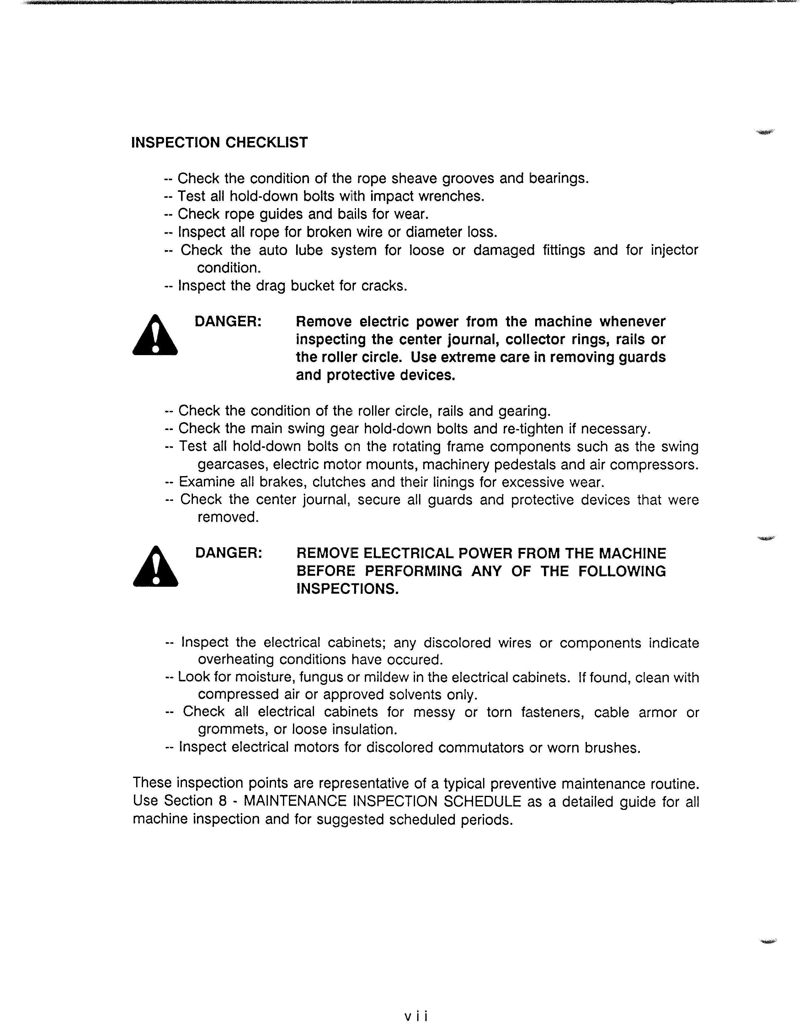
INSPECTION CHECKLIST
-- Check the condition of the rope sheave grooves and bearings. Test all hold-down bolts wiith impact wrenches. Check rope guides and bails for wear. Inspect all rope for broken wire or diameter loss. Check the auto lube system for loose or damaged fittings and for injector condition.
A-- Inspect the drag bucket for cracks.
DANGER: Remove electric power from the machine whenever inspecting the center journal, collector rings, rails or the roller circle. Use extreme care in removingguards and protective devices.
-- Check the condition of the: roller circle, rails and gearing. Check the main swing gear hold-down bolts and if necessary. Test all hold-down bolts on the rotating frame components such as the swing gearcases, electric motor mounts, machinery pedestals and air compressors. Examine all brakes, clutches and their linings for excessive wear. Check the center journal, secure all guards and protective devices that were removed.
ADANGER: REMOVIE ELECTRICAL POWER FROM THE MACHINE BEFORE PERFORMING ANY OF THE FOLLOWING INSPECTIONS.
Inspect the electrical cabinets; any discolored wires or components indicate overheating conditions have occured. Look for moisture, fungus or mildew in the electrical cabinets. If found, clean with compressed air or approved solvents only.
Check all electrical cabinets for messy or torn fasteners, cable armor or grommets, or loose insulation. Inspect electrical motors for discolored commutators or worn brushes.
These inspection points are representative of a typical preventive maintenance routine. Use Section 8- MAINTENANCE INSPECTION SCHEDULE as a detailed guide for all machine inspection and for suggested scheduled periods.
• Thank you very much for reading the preview of the manual.
• You can download the complete manual from: www.heydownloads.com by clicking the link below
• Please note: If there is no response to CLICKING the link, please download this PDF first and then click on it.
PREVENTIVE MAINTENANCE
Machine downtime is costly to owners in lost production. Preventive maintenance is the task of identifying, replacing or repairing machine components before they fail, so that this downtime is minimized.
ACAUTION: Do not perform any inspection activities while the machine is in operation.
Due to variations in operational weat rates of machine components and machine application conditions, component life cycles are different. A scheduled program of machine inspection with accurate record keeping can identify machine components with their rates of wear.
A continuous and careful inspection routine can spot unusual conditions or fatiguing components before a failure occurs. Maintenance, repair and component replacement schedules should conform to scheduled machine shutdowns. If, during daily, weekly or monthly inspection routines, any part shows wear or distortion beyond expected normal patterns, replace them with genuine DRESSER/MARION parts at the next scheduled maintenance interval. The cost of parts is small when compared to unscheduled breakdowns with their resulting lost man-hours and lost machine production.
Machines which operate 24 hours a day, 7 days a week, should have a scheduled 8hour preventive maintenance period each 7-day period. See Section 8- MAINTENANCE INSPECTION SCHEDULE for recommendations.
The preventive maintenance inspection procedures listed below are suggested as an example of typical inspection activities. The owner should establish his own preventive maintenance inspection schedule based on the machine application conditions and the production cycle.
ACAUTION: Maintenance and operating personel should be aware of mechanical adn electrical hazards inherent in servicing this machine.

REPAIR/SPARIE PARTS WARRANTY :i:

••• Dresser Industries, Inc., Marion Division ("Dresser") warrants that its products, when shipped, ••• •:. for a period of six (6) months from the date of delivery, F.G.B. point of shipment, will meet ap-
plicable, agreed specifications, if any with respect thereto, and will be free .from defects in
material and workmanship, provided that the Dresser products sold are properly stored, .:. ••• assembled, used and maintained. Products not manufactured by Dresser shall be subject only to
such warranty as may be made by the manufacturer thereof. All claims under this warranty·:·
must be made in writing immediately upon discovery. THE FOREGOING IS EXPRESSLY IN LIEU
.:. OF ALL OTHER WARRANTIES WHATSOEVER, EXPRESS, IMPLIED AND STATUTORY, IN-
CLUDING, WITHOUT LIMITATION, THE IMPLIED WARRANTIES OF MERCHANTABILITY AND
FITNESS.
•t. Should any failure of the Dresser products to conform to this warranty appear within the limited
•:. time period set forth above, Dresser shall, upon Buyer's submission of a claim as provided .:. •
.:. above, either 1) repair or replace, F.G.B. point of shipment, any nonconforming part or parts of
•:. Dresser's products which have been returned to it for examination, transportation prepaid, or .:••
•:. otherwise examined by Dresser, and which examination discloses the nonconformity to
••• Dresser's satisfaction; or 2) refund an equitable portion of the purchase price.
.:. THE FOREGOING IS DRESSER'S ONLY OBLIGATION AND BUYER'S EXCLUSIVE REMEDY FOR •••
•:. BREACH OF WARRANTIES AND, EXCEPT FOR GROSS NEGLIGENCE, WILLFUL MISCONDUCT, .t•
•:. OR REMEDIES PERMITTED UNDER THE PERFORMANCE, INSPECTION, AND ACCEPTANCE .:•
•+. CLAUSE OF DRESSER'S TERMS AND CONDITIONS, THE FOREGOING IS BUYER'S EXCLUSIVE •••
•:. REMEDY AGAINST DRESSER FOR AL.L CLAIMS ARISING WITH RESPECT TO DRESSER PRO- .:•
•:. DUCTS OR RELATING THERETO, WHIETHER SUCH CLAIMS ARE BASED ON BREACH OF CON- .:•
•:. TRACT, TORT (INCLUDING NEGLIGlENCE AND STRICT LIABILITY) OR OTHER THEORIES.
•t. BUYER'S FAILURE TO SUBMIT A CLAIM AS PROVIDED ABOVE SHALL SPECIFICALLY WAIVE .:•
ALL CLAIMS FOR DAMAGES OR OTHER RELIEF, INCLUDING, BUT NOT LIMITED TO, CLAIMS .:.
••• BASED ON LATENT DEFECTS. .:.
• IN NO EVENT (INCLUDING, BUT NOT LIMITED TO, AVOIDANCE OF THE ABOVE LIMITED WAR- : ..
• RANTIES AND REMEDIES) SHALL BUYER BE ENTITLED TO ANY INDIRECT, SPECIAL, INCIDEN- • .+. .•..
• TAL OR CONSEQUENTIAL DAMAGES, WHETHERARISING FROM LATE PERFORMANCE OR A
• FAILURE TO PERFORM, DEFICIENCIES OR NEGLIGENCE IN THE DESIGN, MANUFACTURE,
•:. SALE DELIVERY OR ASSEMBLY OF DRESSER PRODUCTS OR FAILURE OF DRESSER PRO-
• DUCTS OR FROM ANY CAUSE WHATSOEVER AND WHETHER BASED ON BREACH OF CON- •
•t. TRACT, TORT (INCLUDING NEGLIGENCE AND STRICT LIABILITY) OR OTHER THEORIES. ANY •••
ACTION BY BUYER ARISING WITH RESPECT TO DRESSER PRODUCTS OR RELATING
THERETO MUST BE COMMENCED WITH ONE (1) YEAR AFTER THE CAUSE OF ACTION AC-
•:. CRUES OR IT SHALL BE BARRED.


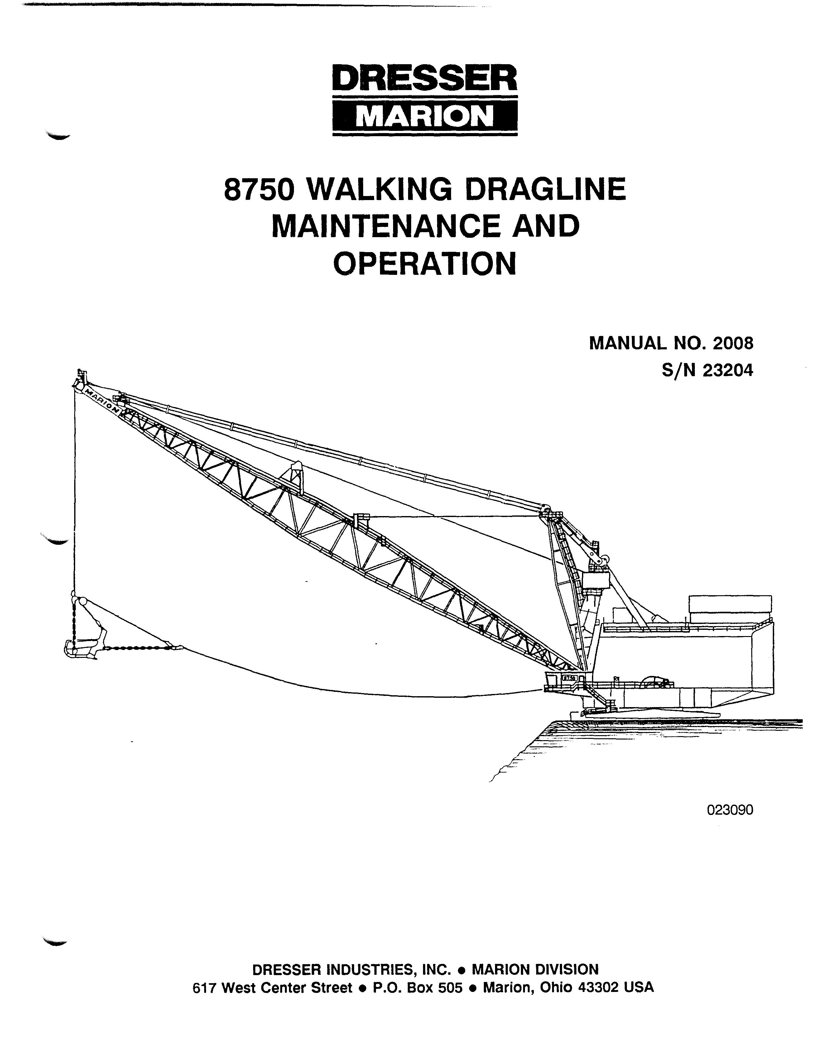
DRESSER
8750 WALKING DRAGLINE
WARD LEONARD - STATIC CONTROL - INDEPENDENT PROPEL
SPECIFICATION 8750-17R
The Company reserves the right to improve or change the design of its products and specifications thereof and the Company shall incur no liability thereby or any obligallons to install such improvements on products pre •.-iously sold.

PRINCIPAL WEIGHTS

• Thank you very much for reading the preview of the manual.
• You can download the complete manual from: www.heydownloads.com by clicking the link below
• Please note: If there is no response to CLICKING the link, please download this PDF first and then click on it.