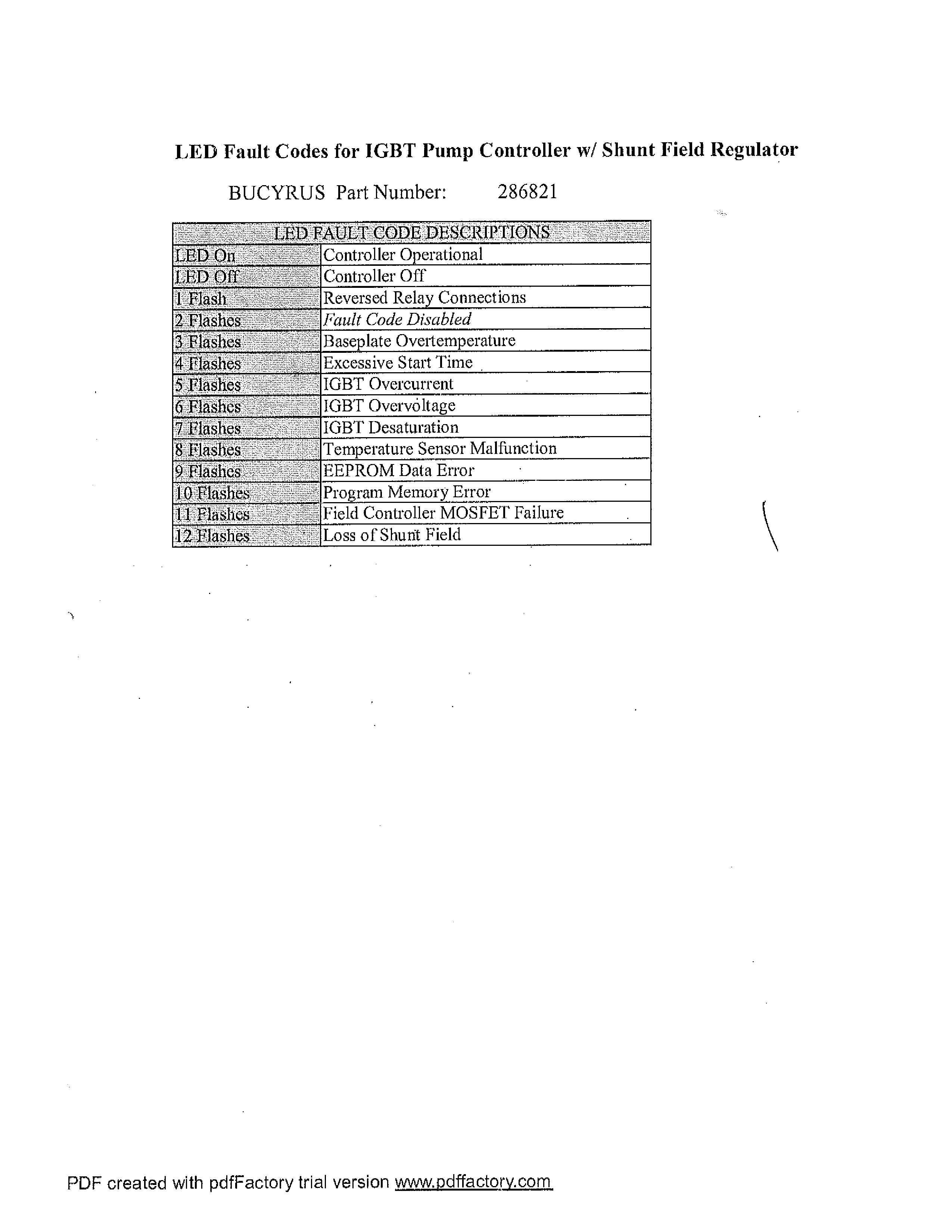
Technical Manual
• Thank you very much for reading the preview of the manual.
• You can download the complete manual from: www.heydownloads.com by clicking the link below
• Please note: If there is no response to CLICKING the link, please download this PDF first and then click on it.

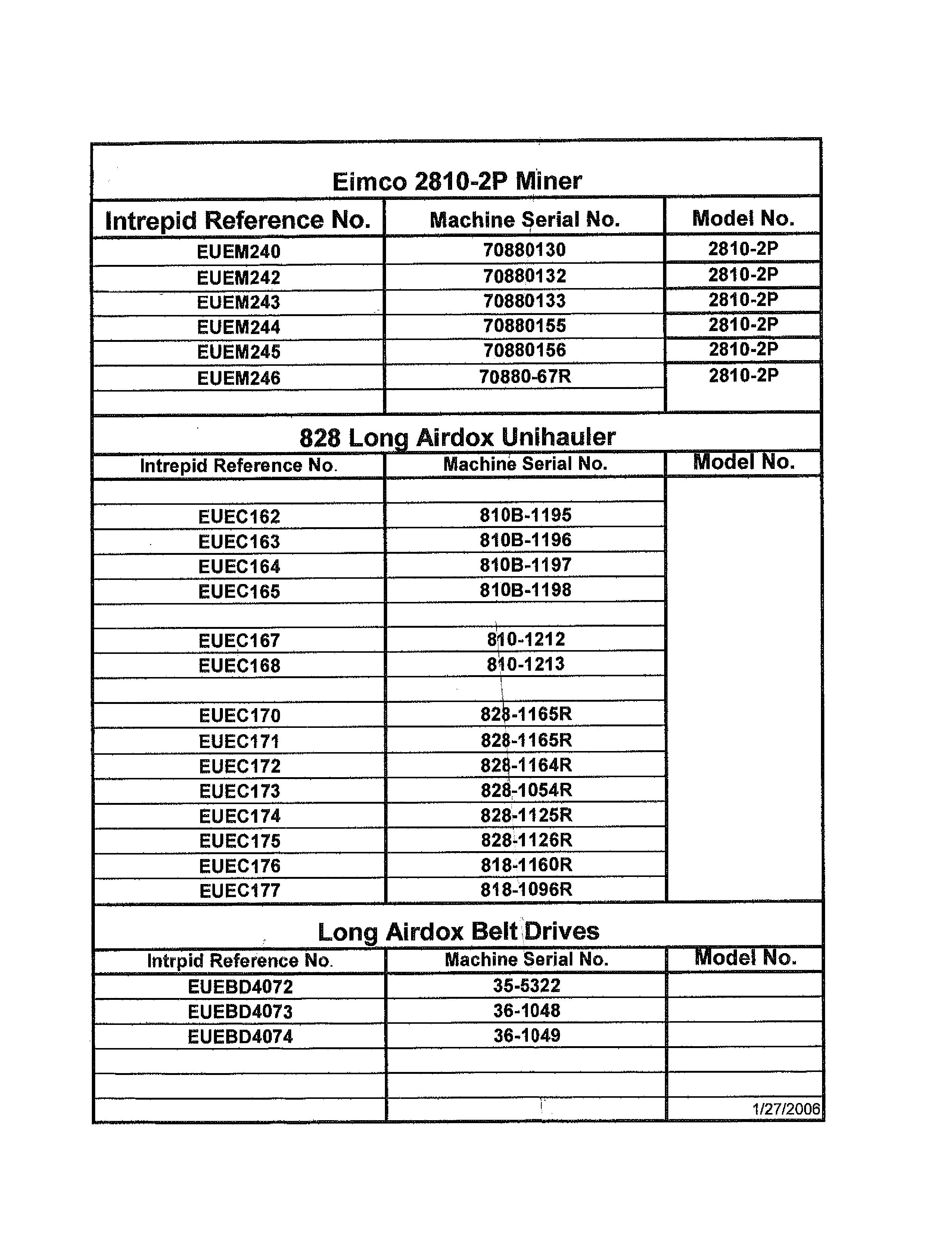
Eimco 2810-2P Miner
Long Airdox Belt Drives
Optional Hand Held Diagnostics/Calibrator Unit
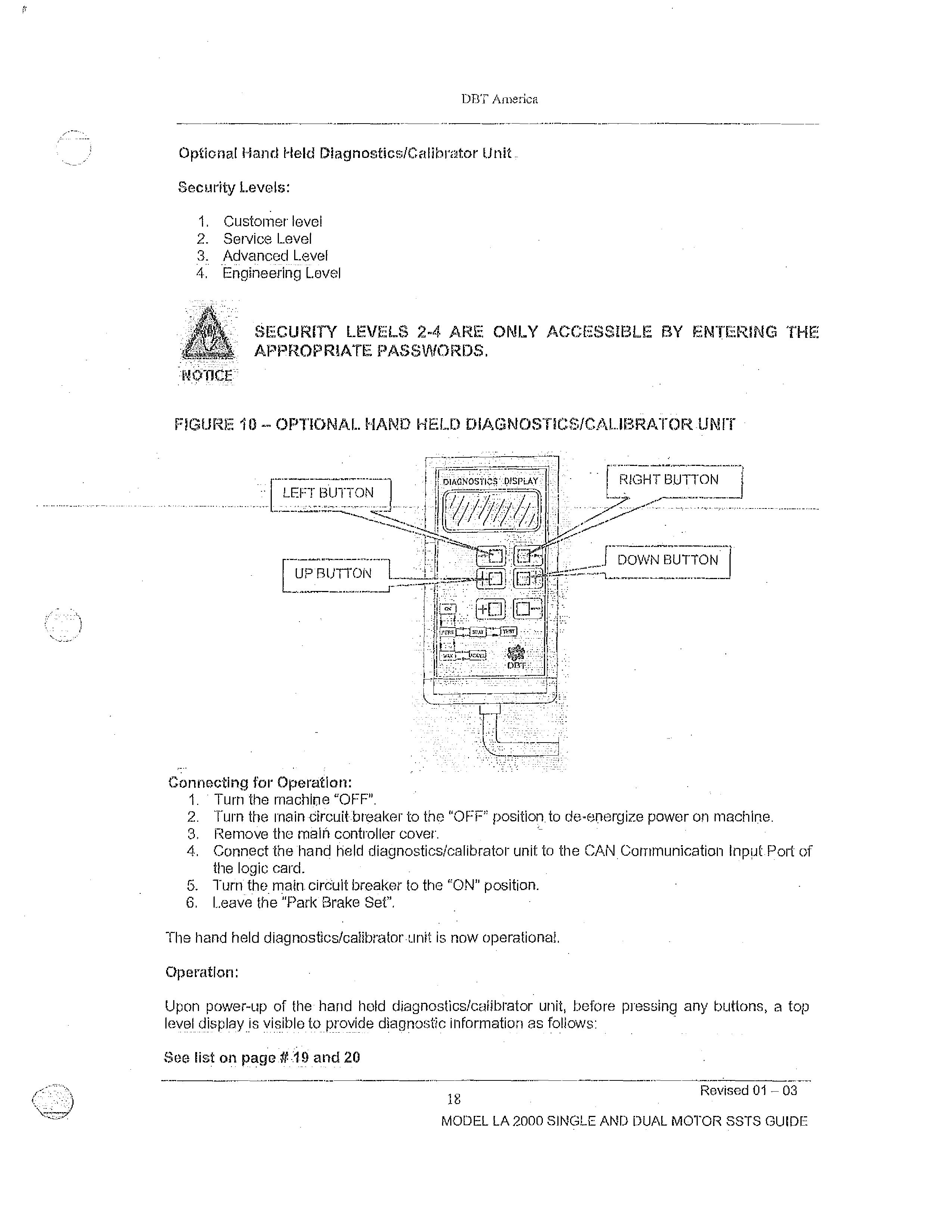
Security Levels:
1. Customer level
2. Service Level
3. Advanced Level
4. Engineering Level
SECURITY LEVELS 2-4 ARE ONLY ACCESS/I:3LE BY ENTERING THE APPROPRIATE PASSWORDS.
FIGURE.
OPTIONAL. HAND HELD DIAGNOSTICS/CALIBRATOR.UNrr
UP173UTTON-1._
Connecting for Operation:
1. Turn the machine "OFF".
2. Turn the main eircuittreaker to the "OFF" position. to de-energize power on machine.
3, Remove the main controller cover.
4. Connect the-hand held diagnostics/calibrator unit to the CAN Communication Input Port of the logic card.
5. Turn - the main. cirduit breaker to the "ON" position.
6. Leave the "Park Brake Set",
The hand held diagnostics/calibrator unit is now operational.
Operation:
Upon power-up of the hand held diagnostics/calibrator unit, before pressing any buttons, a top level display is visible to provide diagnostic information as follows:
See list on page 19 and 20 Revised
Personality Adjustment Procedure
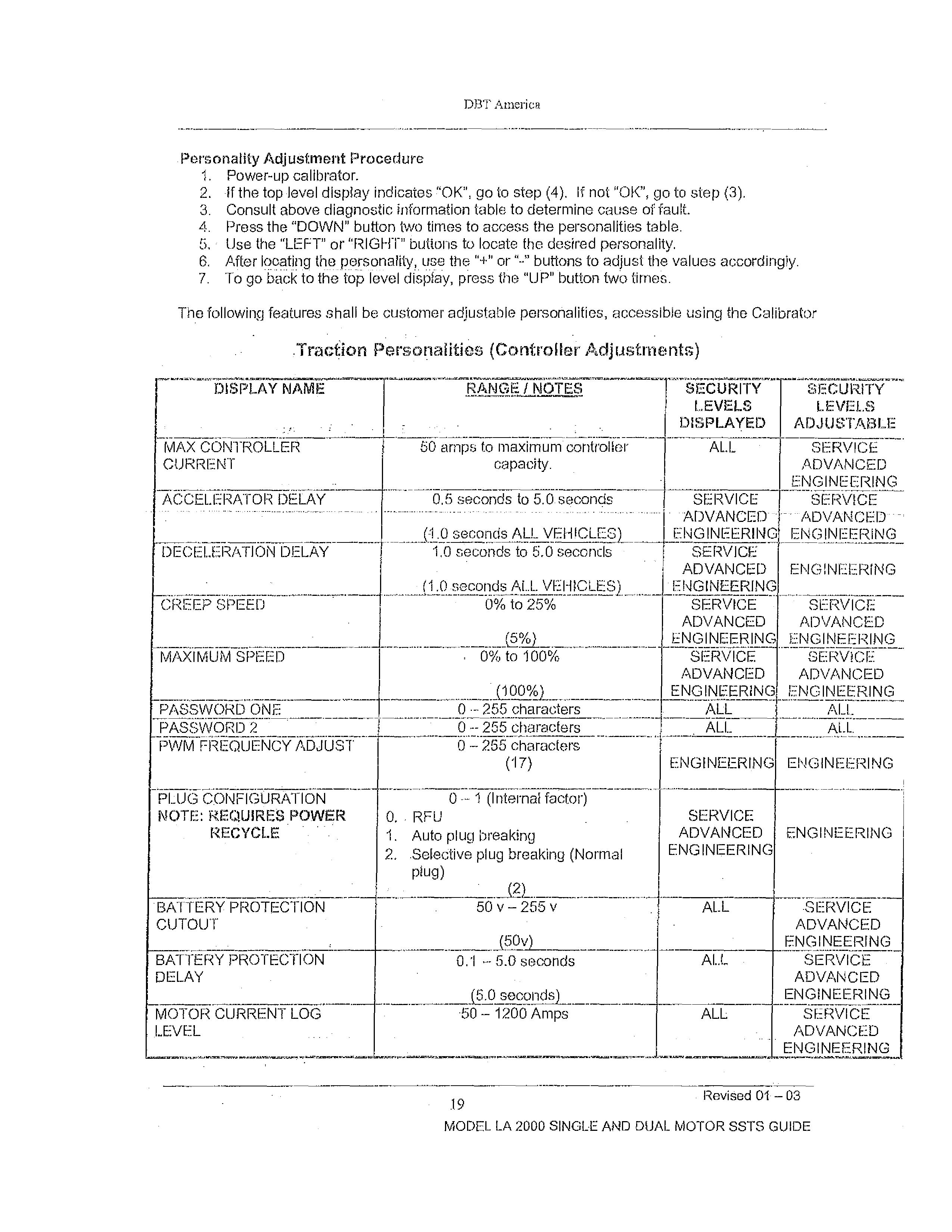
1. Power-up calibrator.
2. if the top level display indicates "OK", go to step (4). If not "OK", go to step (3).
3. Consult above diagnostic information table to determine cause of fault.
4. Press the "DOWN" button two times to access the personalities table.
5.- Use the "LEFT" or 'RIGHT" buttons to locate the desired personality.
6. After locating the personality, use the "+" or "--" buttons to adjust the values accordingly.
7. To go back to the top level display, press the "UP" button two times.
The following features shall be customer adjustable personalities, accessible using the Calibrator
DECELERATION DELAY
CREEP SPEED
IC/iA1_ji\.il§IYE--.ffrT------r----------TR,
2
1.
DBT
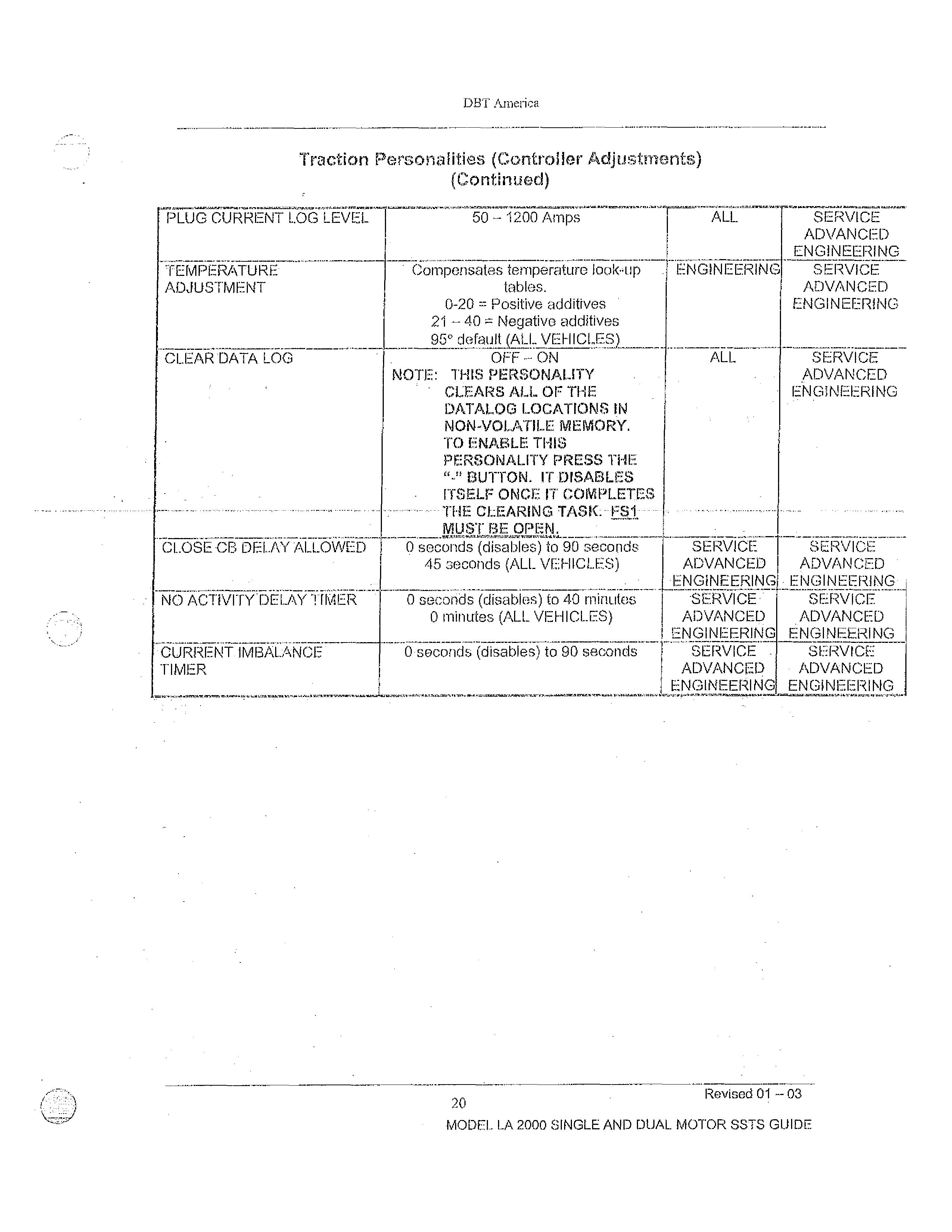
Traction Personalities (Controller Adjustments) (Continued)
50 — 1200 Amps
TEMPERATURE ADJUsTmENT
Compensates temperature look-up tables.
0-20 = Positive additives
21 — 40 = Negative additives
95° default (ALL VEHICLES)
ENGINEERING
SERVICE ADVANCED ENGINEERING
ADVANCED ENGINEERING
CLEAR DATA LOG --
OFF ON
NOTE THIS PERSONALITY CLEARS ALL OF THE DATALOG LOCATIONS IN NON-VOLATILE MEMORY. TO ENABLE THIS PERSONALITY PRESS THE "-" BUTTON. IT DISABLES ITSELF ONCE IT COMPLETES THE CLEARING TASK. FSI MUST BE OPEN.
ALL
CLOSE DELAY ALLOWED
NO ACTIVITY DELAY
•CURRENT IMBALANCE TIMER
Q seconds (disables) to 90 seconds
45 seconds (ALL VEHICLES)
0 seconds (disables) to 40 minutes
0 minutes (ALL VEHICLES)
0 seconds (disables) to 90 seconds
SERVICE ADVANCED ENGINEERING ----.7cZ.0iof --
ADVANCED ENGINEERING
SERVICE
ADVANCED
ENGINEERING
Wiaf ADVANCED ENGINEERING
---
ADVANCED ENGINEERING
SE=RVICE
ADVANCED
20 Revised
01-03
For Reservations Call 1-800-WESTERN

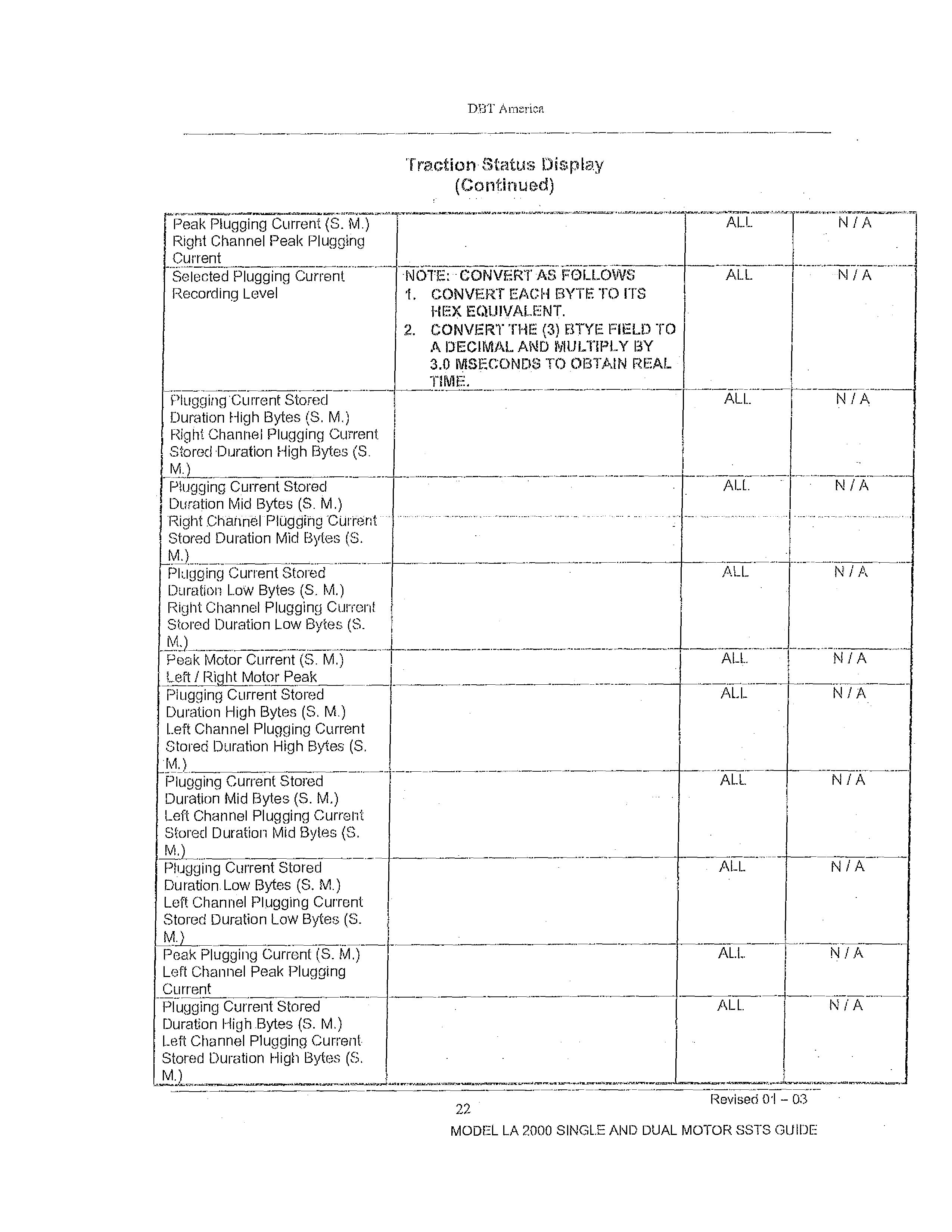
Plugging Current Stored
Duration Mid Bytes (S. M.)
Left Channel Plugging Current
Stored-Duration Mid-Bytes (S.
1).11.)
Plugging Current Stored
Duration Low Bytes (S. M.)
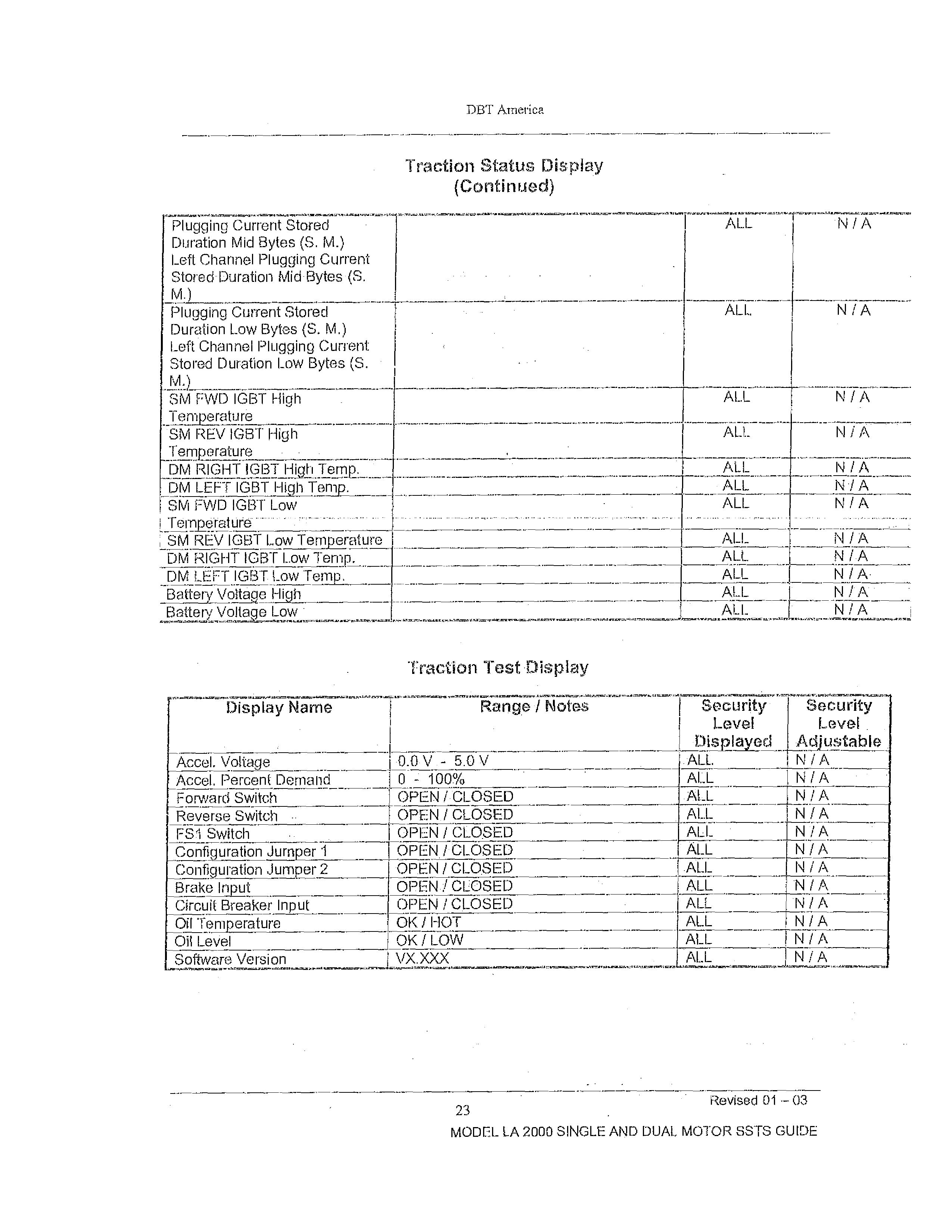
Left Channel Plugging Current
Stored Duration Low Bytes (S.
Gk~ FVVD|GBTHigh
Traction Status Display (Continued)
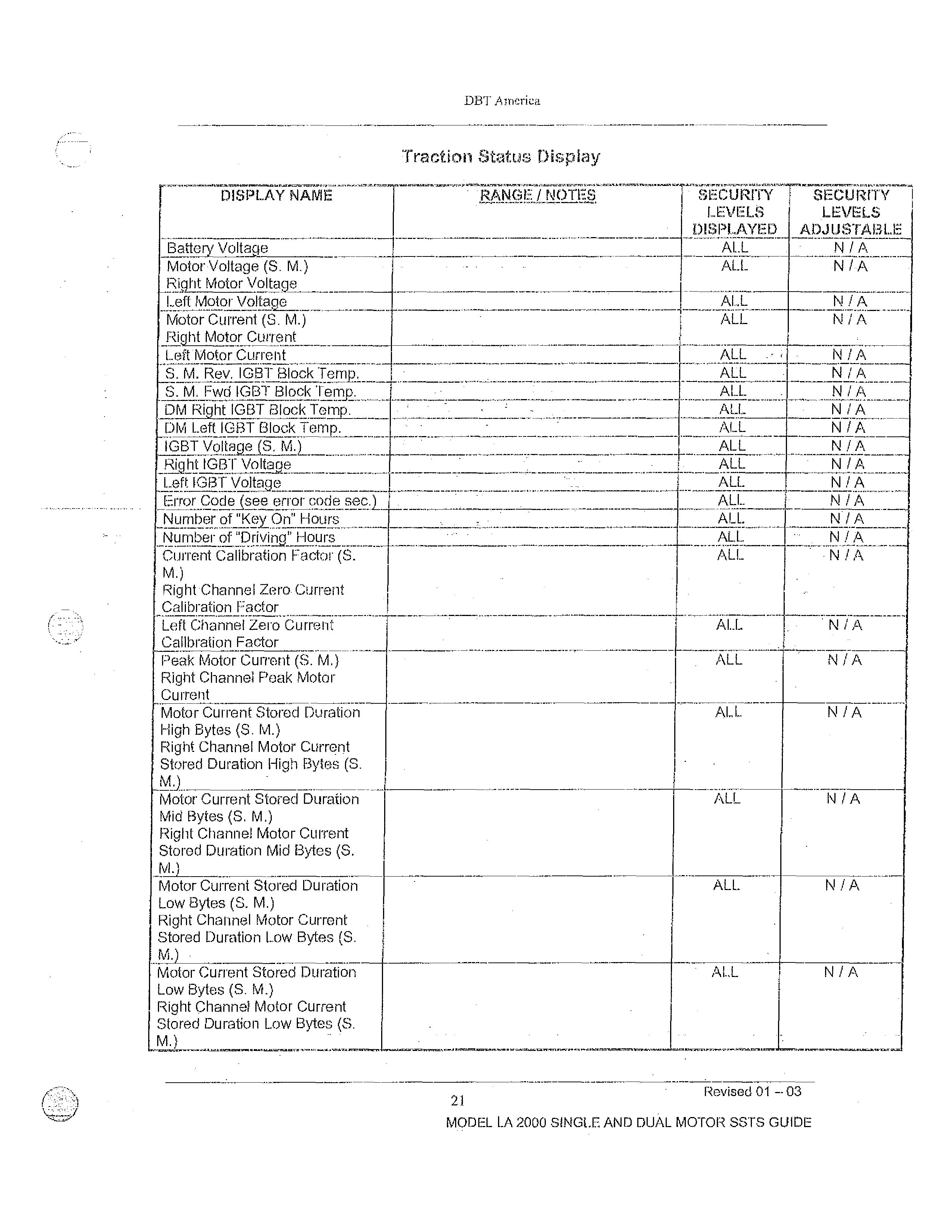
Traction Test.Display
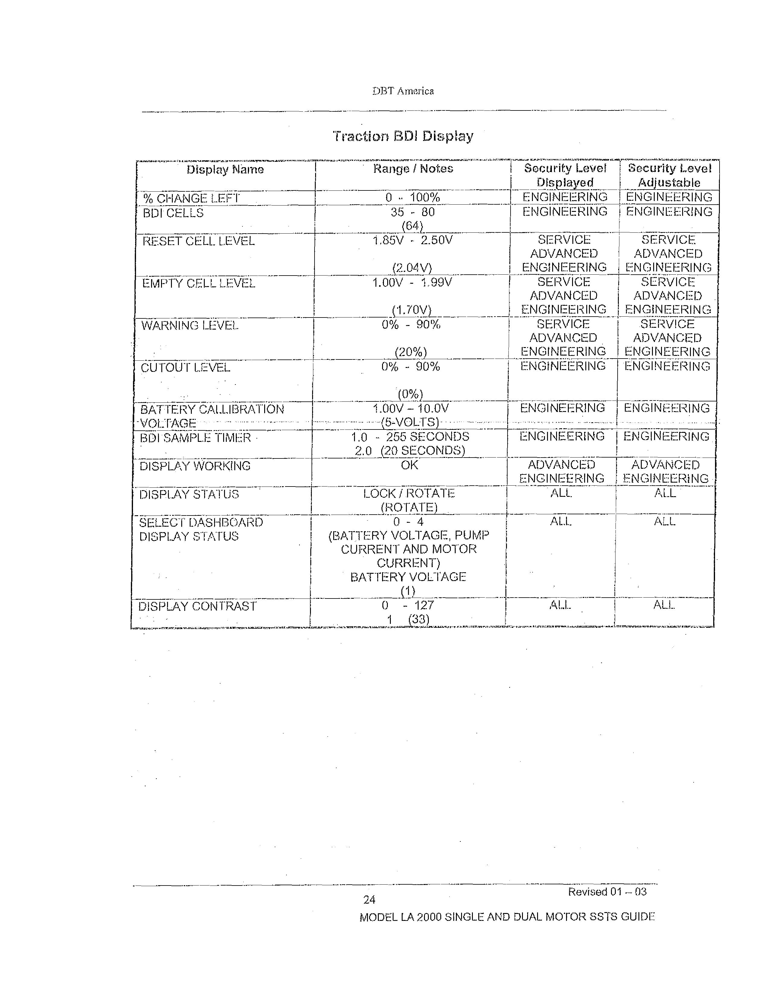
Traction BD! Display
Fault Message Chart
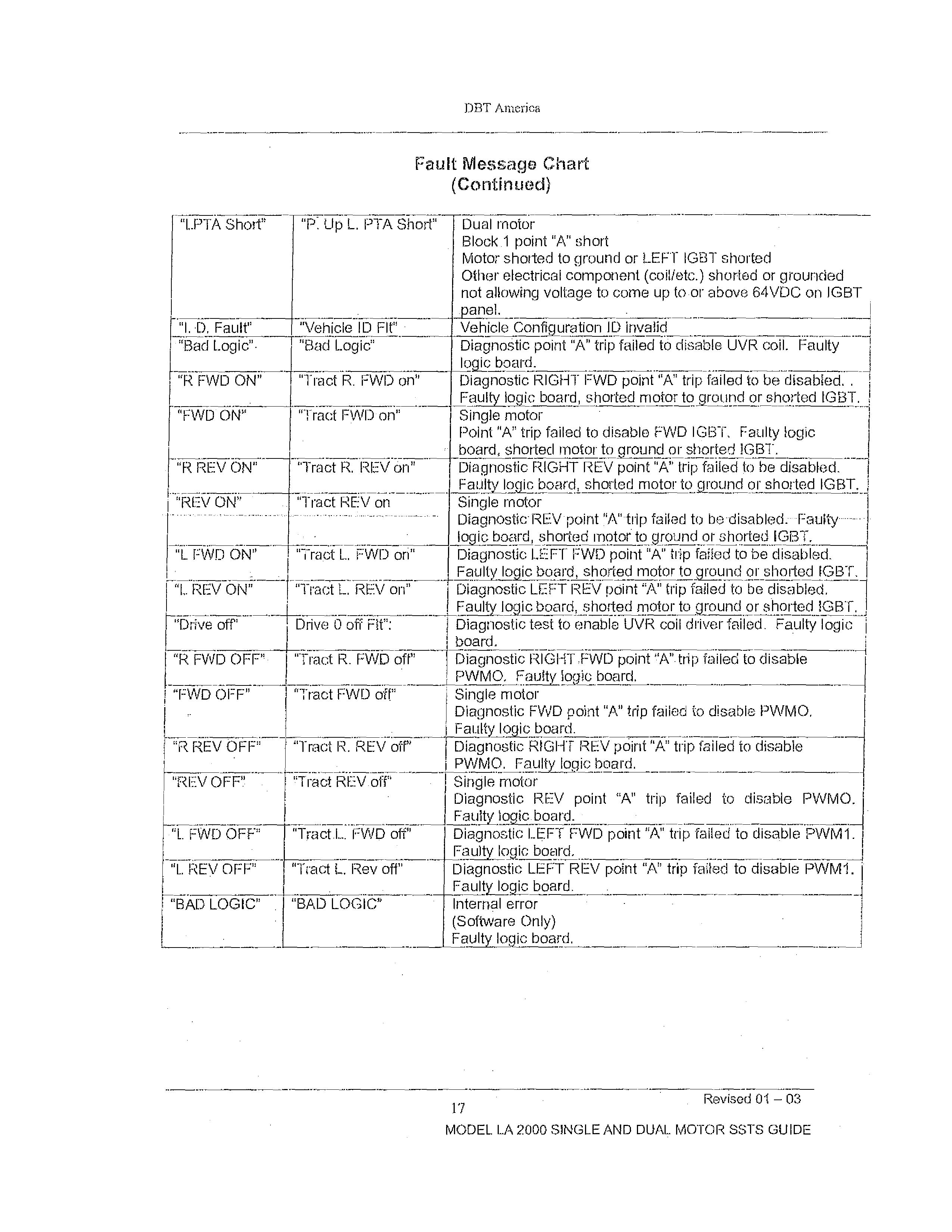
(Continued)
"LPTA Short" "P. Up L. PTA Short" Dual motor Block.1 point "A" short Motor shorted to ground or LEFT IGBT shorted Other electrical component (coil/etc.) shorted or grounded not allowing voltage to come up to-or above 64VDC on 1GBT panel.
"I. Fault" "Vehicle ID Flt" - Vehicle Confikuration ID invalid
I "Bad Logic". "Bad Logic"
"R FWD ON" "Tract R. FWD on"
"FWD ON" "Tract FWD on"
"R REV ON" "Tract R. REV on"
Diagnostic point "A" trip failed to disable UVR coil. Faulty loge board.
Diagnostic RIGHT FWD point "A" trip failed to be disabled. . Faulty logic board, shorted motor toground or shorted IGBT. -.;
Single motor
Point "A" trip failed to disable FWD IGBT, Faulty logic board, shorted motor to ground or shorted IGBT.
Diagnostic RIGHT REV point "A" trip failed to be disabled. i FaUlty logic board, shorted motor to ground or shorted IGBT.
"REV ON" "Tract REV on .Single motor
"L. FWD ON" "Tract L. FWD on"
"I... REV ON" "Tract L REV on"
"Drive off' Drive 0 off Fit":
"R FWD OFF" "Tract R. FWD off'
"FWD OFF" "Tract FWD oft"
"P REV OFF" "Tract R. REV off"
"REV OFF" "Tract REV.off"
"L. FWD OFF" "Tract.1.... FWD off"
Diagnostic-REV-point "A"-trip failed to be-disabled:--Faulty logic board, shorted motor to ground or shorted IGBT.
Diagnostic LEFT FWD point "A" trip failed to be disabled. Faulty logic board, shorted motor to ground or shorted IGBT.
Diagnostic LEFT REV point "A" trip failed to be disabled, 1 Faulty logic board, shorted motor to ground or shorted IGBT. _.
Diagnostic test to enable UVR coil driver failed. Faulty logic board.
Diagnostic RIGHT,FWD point'A".trip failed to disable PWMO. Faulty logic board.
Single motor
Diagnostic FWD point "A" trip failed to disable PWMO, Farb logic board.
Diagnostic RIGHT REV point "A" trip failed to disable -I PWMO. Faulty logic board.
Single motor
Diagnostic REV point "A" trip failed to disable PWMO. Faulty logig.board.
Diagnostic LEFT FWD point "A" trip failed to disable PWM1. Faulty logic board.
"L. REV OFF" "Tract L. Rev off' Diagnostic LEFT REV point "A" trip failed to disable PWM1. Faultylogic board.
"BAD LOGIC" "BAD LOGIC" Internal error
(Software Only)
Faulty logic board.
MODEL LA 2000 SINGLE AND DUAL MOTOR SSTS GUIDE
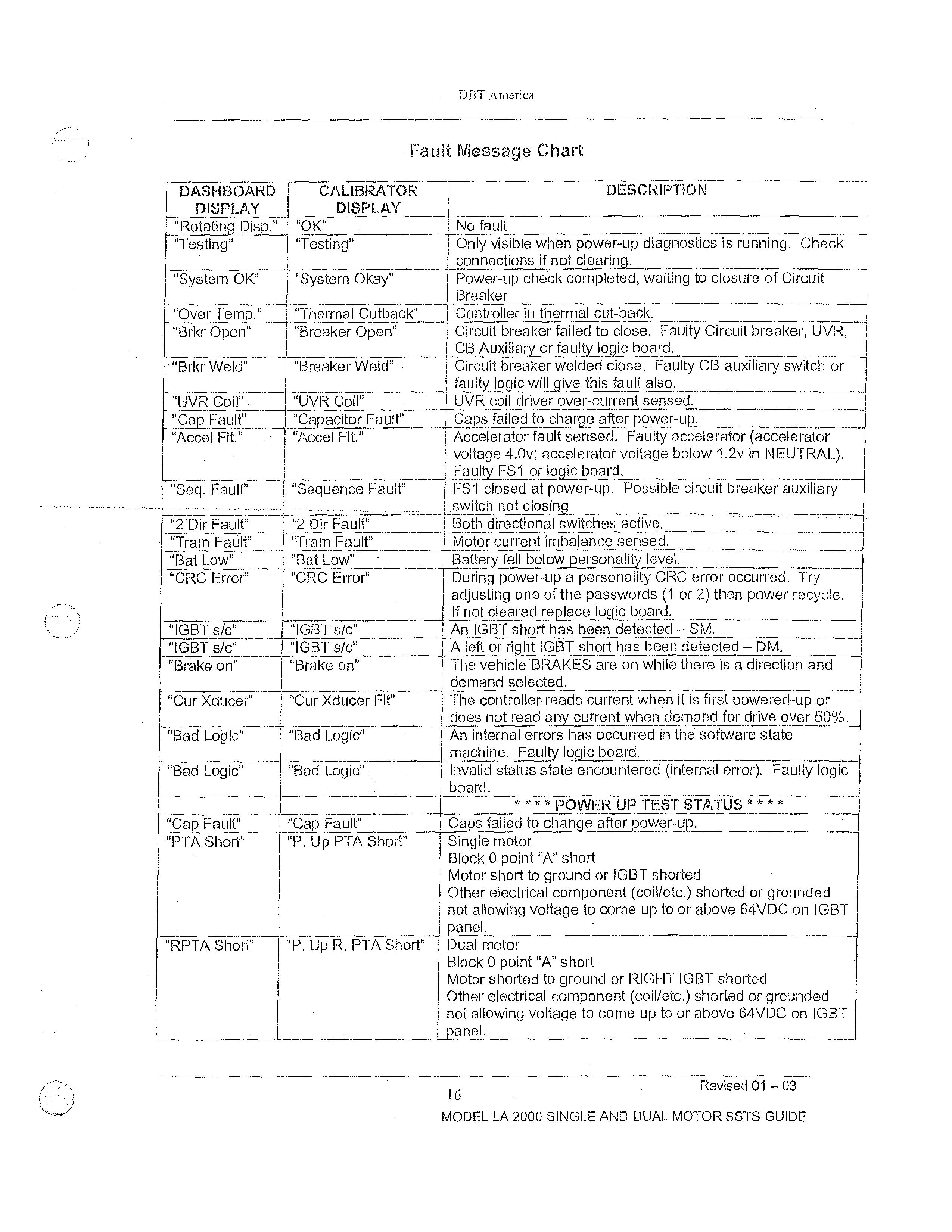
- Fault Message Chart
DASHBOARD DISPLAY I CALIBRATOR DESCRIPTION DISPLAY
L.
"Rotating Disp." "OK" I No fault ._
"Testing" "Testing" i Only visible when power-up diagnostics is running. Check i connections if not clearing. _I
"'System OK" "System Okay" l Power-up check completed, waiting to closure of Circuit Breaker
"Over Temp." "Thermal Cutback" 1 Controller in thermal cut-back.
"Brkr Open" "Breaker Open" I Circuit breaker failed to close, Faulty Circuit breaker, UVR, i CB Auxiliary or faulty logic board.
•"Brkr Weld" "Breaker Weld" • 1 Circuit breaker welded close. Faulty CB auxiliary switch or 1 faulty lb is will give this fault also. L.
"UVR Coil" . "UVR Coil" ' UVR coil driver over-current sensed.
"Cap Fault" "Accel Fit." .—
"Seq. -Fault"
"Capacitor Fauff l Caps failed to charge after_powe,r-up.
"Accel Flt." Accelerator fault sensed. Faulty accelerator (accelerator voltage 4.0v•. accelerator voltage below 1.2v in NEUTRAL). l Faulty FS'1 or logic board.
"Sequence Fault" i FS1 closed at power-up. Possible circuit breaker auxiliary I .1'switch not closing
"2 Dir•Fault" "2 Dir Fault" Both directional switches active.
"Tram Fault" "Tram Fault" i Motor current imbalance sensed.
"Bat Low" "Bat Low" - 1 Battery fell below personality level. ...
"CRC Error" "CRC Error" I During power-up a personality CRC error occurred. Try adjusting one of the passwords (1 or 2) than power recycle,. If not cleared replace logic board.
"IGBT s/c" "IGB-f sic" i An IGB-r short has been detected — SM.
"IGBT sic" ."IGBT sic" I A left or right IGBT short has been detected — DM.
"Brake on" - "Brake on" The vehicle-BRAKES are on while there is a direction and demand selected. _..
"Cur Xducer" "Cur Xducer FR" I The controller reads current when it is first-powered-up or does not read any current when demand for drive over 50%.
"Bad Logic" "Bad Logic" ! An internal errors has occurred in the - software state machine. Faulty logic board.
"Bad Logic" "Bad Logic". I Invalid status state encountered (internal error). Faulty logic --1 I board.
**** POWER UP TEST§TATUS **
"Cap Fault" "Cap Fault" 1 Caps failed to change after power-up.
"PTA Short" "P. Up PTA Short" 1 Single motor
I Block 0 point "A" short
I Motor short to ground or IGBT shorted
Other electrical component (coil/etc.) shorted or grounded
I not allowing voltage to come up to or above 64VDC on 1GBT panel.
"RPTA Short" "P. Up R. PTA Short' I Dual motor
Block 0 point "A" short
Motor shorted to ground or RIGHT IGBT shorted
Other electrical component (coil/etc.) shorted or grounded not allowing voltage to come up to or above 64VDC on IGBT panel.
Revised 01 --03
MODEL LA 2000 SINGLE AND DUAL MOTOR SSTS GUIDE
TROUBLE SHOOTING CHECKLIST
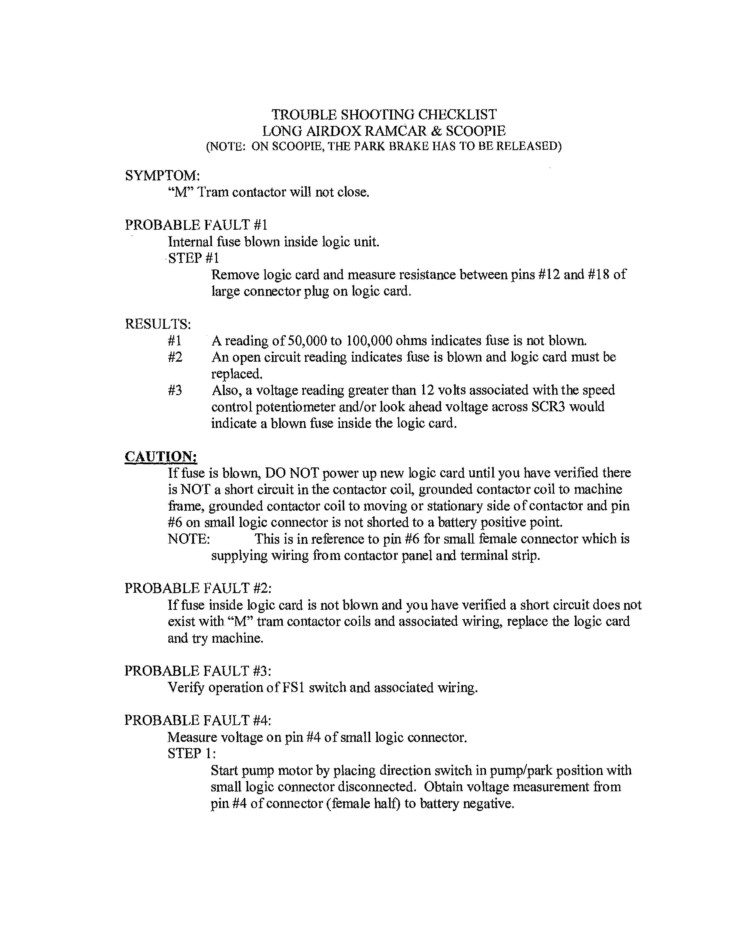
LONG AIRDOX RAMCAR & SCOOPIE (NOTE: ON SCOOPIE, THE PARK BRAKE HAS TO BE RELEASED)
SYMPTOM:
"M" Tram contactor will not close.
PROBABLE FAULT #1
Internal fuse blown inside logic unit.
STEP #1
Remove logic card and measure resistance between pins #12 and #18 of large connector plug on logic card.
RESULTS:
#1 A reading of 50,000 to 100,000 ohms indicates fuse is not blown.
#2 An open circuit reading indicates fuse is blown and logic card must be replaced.
#3 Also, a voltage reading greater than 12 volts associated with the speed control potentiometer and/or look ahead voltage across SCR3 would indicate a blown fuse inside the logic card.
CAUTION;
If fuse is blown, DO NOT power up new logic card until you have verified there is NOT a short circuit in the contactor coil, grounded contactor coil to machine frame, grounded contactor coil to moving or stationary side of contactor and pin #6 on small logic connector is not shorted to a battery positive point.
NOTE: This is in reference to pin #6 for small female connector which is supplying wiring from contactor panel and terminal strip.
PROBABLE FAULT #2:
If fuse inside logic card is not blown and you have verified a short circuit does not exist with "M" tram contactor coils and associated wiring, replace the logic card and try machine.
PROBABLE FAULT #3: Verify operation of FS1 switch and associated wiring.
PROBABLE FAULT #4: Measure voltage on pin #4 of small logic connector.
STEP 1:
Start pump motor by placing direction switch in pump/park position with small logic connector disconnected. Obtain voltage measurement from pin #4 of connector (female half) to battery negative.
RESULTS:
#1 "0" volts indicates circuit to be satisfactory.
#2 Voltage greater than "0" volts indicates a problem with FS1 switch in accelerator not returning to it's normally open position when accelerator pedal is released. If FS1 switch is operating normal, check the wiring which is supplying pin #4, making sure it is not shorted to another battery positive point.
PROBABLE FAULT #5
Measure voltage on pin #16 of small logic connector (female half).1
STEP #1:
Start pump motor by placing direction switch in pump/park position with small logic connector disconnected. Obtain voltage measurement from pin #16 of connector (female half) to battery negative.
RESULTS:
#1 Voltage reading of 128 volts indicates circuit to be satisfactory.
#2 "0" volt reading indicates an open circuit in wiring supplying pin #16.
PROBABLE FAULT #6:
Check wiring associated with pin #6 of small logic connector (female half).
PROBABLE FAULT #8:
Faulty wiring or R2A resistor located on SCR panel.
STEP 1:
RESULTS:
Disconnect both logic connectors. Measure resistance between pins #1 & #6 of large connector.
A reading of 1000 ohms indicates this circuit to be satisfactory.
#2 An open circuit indicates the wiring or resistor to be open and must be repaired or replaced.
#3 A direct reading indicates a short circuit resistor or wiring and must be repaired or replaced.
PROBABLE FAULT #9:
Check for shorted or leaky SCR1 forward and reverse.
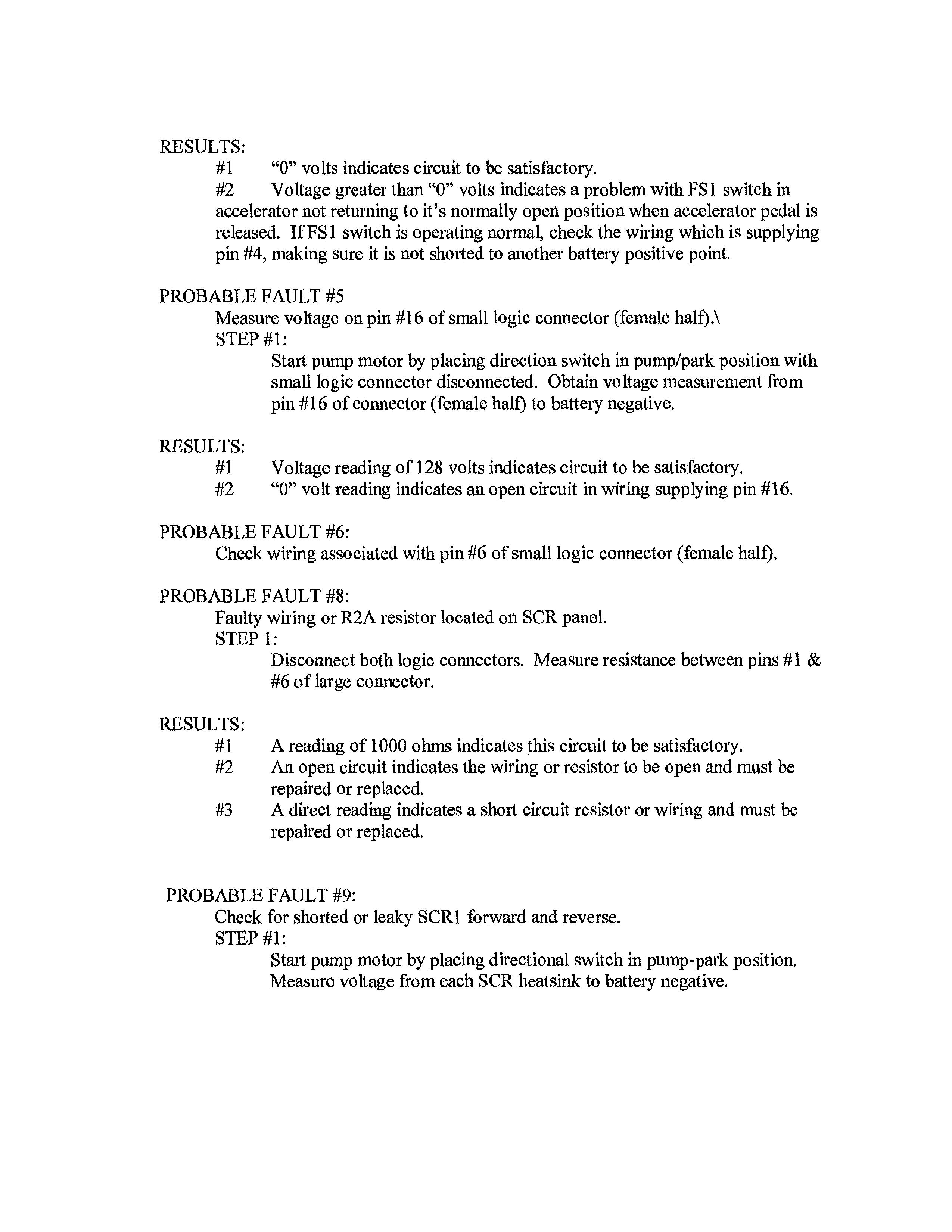
STEP #1:
Start pump motor by placing directional switch in pump-park position, Measure voltage from each SCR heatsink to battery negative.
RESULTS:
#1 9 volts or greater indicates SCR's are not shorted or leaky.
#2 Less than 9 volts indicates a problem with an SCR. To Determine which SCR is faulty, disconnect the S1L, S4L, S1R and S4R motor leads from heatsink. Repeat step #1 and replace the SCR with the voltage less than 9 volts.
PROBABLE FAULT #10
Check for shorted or leaky SCR3, or shorted capacitor bank.
STEP#1: Start pump motor by placing directional switch in pump/park position. Measure voltage across SCR3.
RESULTS:
#1 7.5 volts or greater indicates SCR3 and cap bank to be satisfactory.
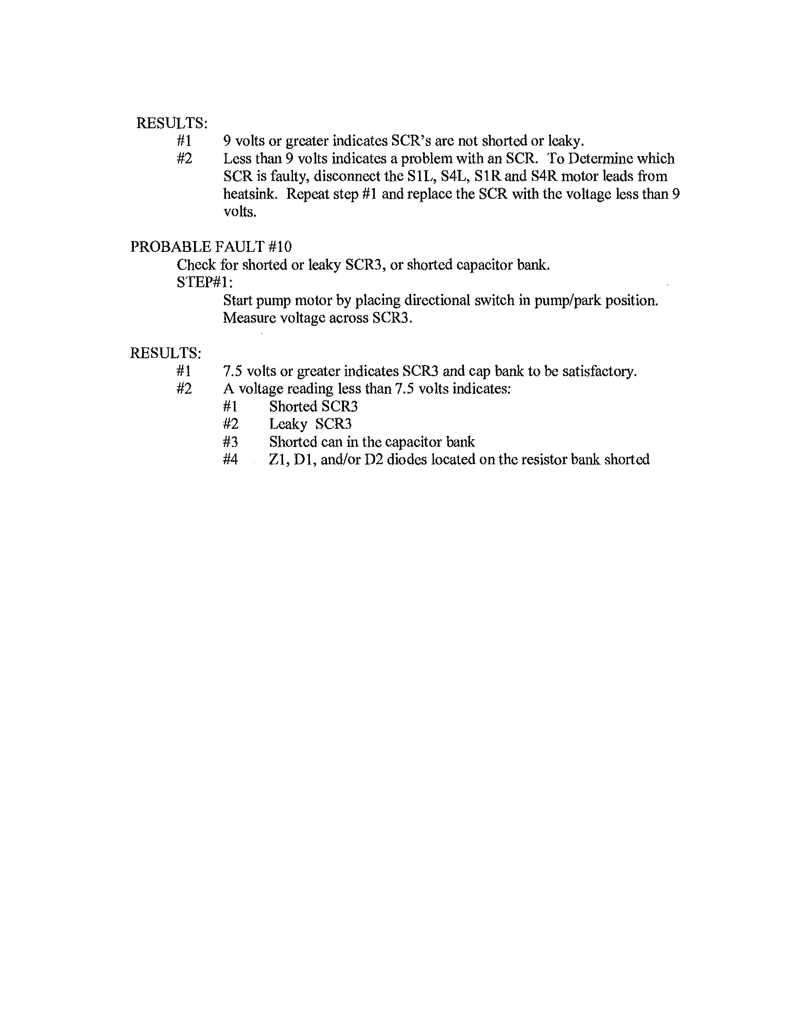
#2 A voltage reading less than 7.5 volts indicates:
#1 Shorted SCR3
#2 Leaky SCR3
#3 Shorted can in the capacitor bank
#4 Z1, D1, and/or D2 diodes located on the resistor bank shorted
Sparky, FYI-Let's talk.
Tim McCallum
BUCYRUS
General Manager
Western Region
Phone 435-687-1216
Mobile 724-263-3112
Fax 435-687-1217
tim.inceallum@us.bucyrus.com www.bucyrus.com
From: Chacon, Paul
Sent: Monday, June 23, 2008 1:23 PM
To: McCallum, Timothy
Cc: Martinez, Steven
Subject: FW: Bucyrus requirements
FYI
From: Ralph Ramstetter [mailto:ralph.rannstetter@intrepfdpotash.corn]
Sent: Monday, June 23, 2008 11:11 AM
To: Chacon, Paul
Cc: Robert Baldridge
Subject: Bucyrus requirements
Paul,
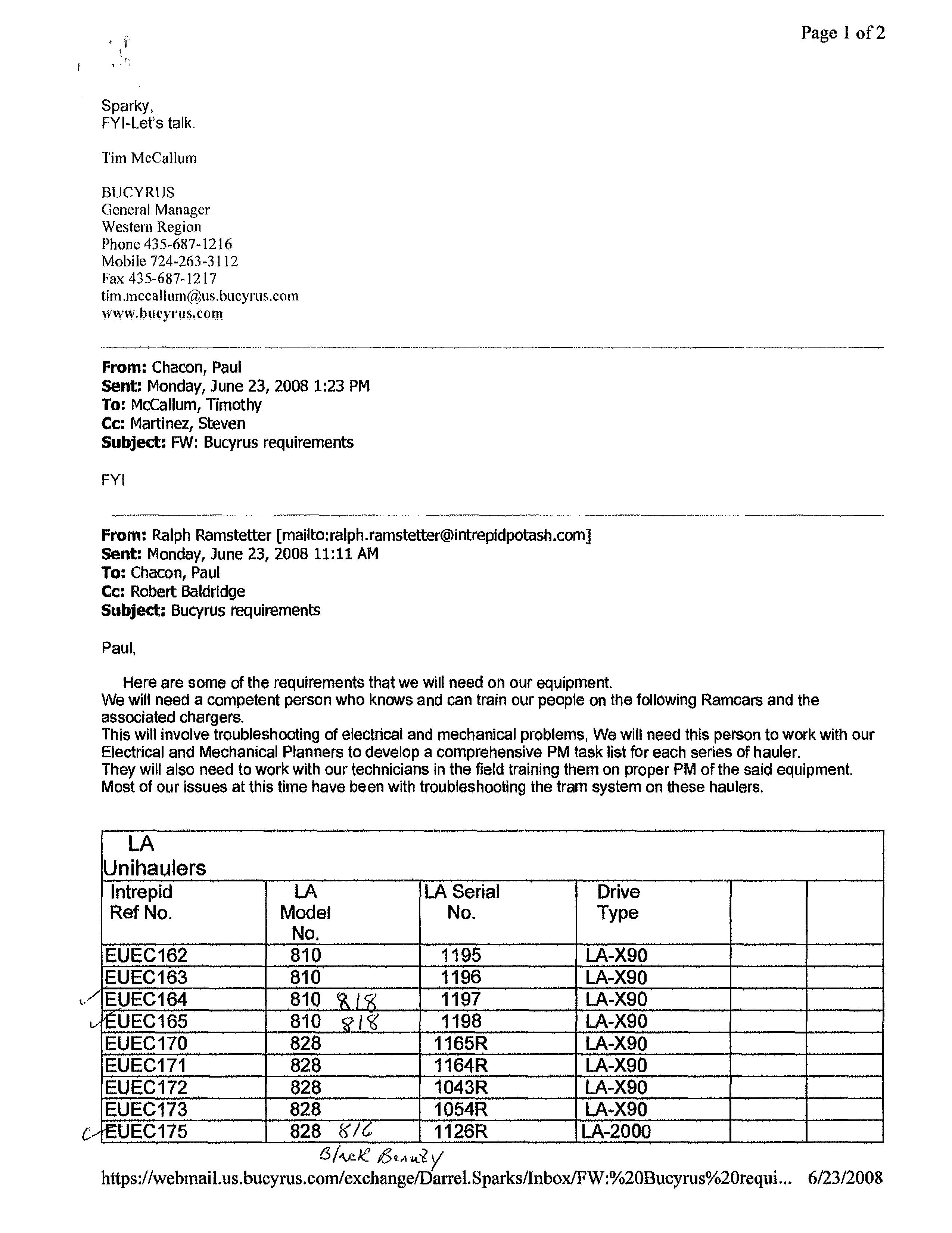
Here are some of the requirements that we will need on our equipment. We will need a competent person who knows and can train our people on the following Ramcars and the associated chargers.
This will involve troubleshooting of electrical and mechanical problems, We will need this person to work with our Electrical and Mechanical Planners to develop a comprehensive PM task list for each series of hauler. They will also need to work with our technicians in the field training them on proper PM of the said equipment. Most of our issues at this time have been with troubleshooting the tram system on these haulers. LA
Unihaulers
https://webmail.us.bucyrus.com/exchange/Darrel.Sparks/Inbox/FW:%2013ucyrus%2Orequi...
• Thank you very much for reading the preview of the manual.
• You can download the complete manual from: www.heydownloads.com by clicking the link below
• Please note: If there is no response to CLICKING the link, please download this PDF first and then click on it.