Technical Manual
© Bucyrus All Rights Reserved
R
BI005444
BUCYRUS


This manual establishes guidelines and furnishes general instructions for the operation of the BucyrusErie® 45-R Rotary Blast Hole Drill.
This drill can be powered either by a diesel engine or an electric trail cable. In either case, all motions are fully electric. The drill consists of three major units; the lower works, the mainframe, and the mast.
The lower works provides a foundation for the mainframe and contains most the necessary components to propel the drill.
The mainframe is mounted upon the lower works and contains the bailing air compressor, hoist machinery, and all controls to operate the drill. The machinery house encloses most of the mainframe. The operator's cab is located at the rear of the mainframe and contains the operator's station.
The mast is mounted to the rear of the mainframe and contains the machinery required for rotation and handling of the tool string.
This manual is divided into seven sections:
SECTION 1 - Safety Precautions and Prestart Checks
SECTION 2 - Controls-Function and Location
SECTION 3-Start-Up
SECTION 4 - General Operation
SECTION 5 - Drilling
SECTION 6 - Shut Down
CAUTION: Before attempting to operate the drill, read this manual completely. Familiarize yourself with the contents of this manual so that you can easily locate particular information when you need it.
Throughout this manual the words CAUTION, WARNING and NOTE appear in bold face type. CAUTION is preceded by the safety alert symbol A and indicates that injury to personnel could occur if the proper procedures are not followed during operation or maintenance. Always read the CAUTION note carefully and use extreme care while performing that particular function.

WARNING indicates a possible hazard to the machine or its components if the proper procedures are not followed. Whenever the word WARNING appears, special attention should be given to prevent possible equipment damage.
NOTE is used to stress a point or to give additional information concerning the procedure being discussed.
These CAUTION's and WARNING's are not all-inclusive. It is impossible for Bucyrus-Erie Company to know, evaluate, and advise maintenance and service personnel in every conceivable way a service operation might be performed and of the resulting possible hazardous consequences of each method. It is therefore extremely important that anyone who uses a service procedure or tool which is not recommended by Bucyrus-Erie Company to first satisfy himself that the service procedure or tool he chooses will not jeopardize his own safety, the safety of others, or cause machine or component damage.
Every effort has been made to make this manual as complete and accurate as possible at the time of publication. Bucyrus-Erie Company reserves the right, however, to continually improve its products. Therefore changes to the equipment described herein may have been made that are not reflected in this manual.
• Thank you very much for reading the preview of the manual.
• You can download the complete manual from: www.heydownloads.com by clicking the link below
• Please note: If there is no response to CLICKING the link, please download this PDF first and then click on it.

CAT BUCYRUS-ERIE 45-R Blast Hole Drill OPERATOR'S MANUAL - PDF DOWNLOAD
Language : English
Pages :179
Downloadable : Yes
File Type : PDF


•
Ensure that all personnel are clear of the machine when propelling.
Do not propel the machine on a slope greater than specified in the stability limits in appendix.
Do not leave the rotary gearcase suspended in the air when leaving the machine unattended. Always wear approved rubber gloves, and use insulated hooks or tongs when handling trail cable.
SPECIFIC SAFETY RULES

Wear hard hat, safety shoes and safety glasses at all times.
When operating or performing maintenance functions, wear snug fitting clothing. Loose clothing can be caught on controls or in moving parts. Remove all jewelry.
Keep the operator's cab, ladders, walkways and steps free of materials which cause slippery conditions or obstacles which create tripping hazards.
Use proper interior and exterior lighting. Do not allow unauthorized personnel on board the machine while in operation.
Do not begin operation until all personnel are clear of the machine or in a safe position on the machine.
Use audible signals to warn of machine movements. A signal horn button is provided for this purpose.
• • • •
Prevent trail cable from being dragged on the ground for long distances or at high speeds. Limit the amount of cable being dragged by the machine. Pulling too much cable will damage both the cable and the machine.
Use extreme caution when working around loaded blast holes.
OPERATION NEAR ELECTRICAL TRANSMISSION LINES*
*Permission to reproduce the following material has been granted by the Construction Industry Manufacturers Association (CIMA). CIMA assumes no responsibility for the accuracy of this reproduction.
h CAUTION: The following precautions shall be complied with whenever operating near electrical transmission lines.
Working in the vicinity of electrical power lines presents a very serious hazard and special precautions must be taken. For purposes of this manual you are considered to be working in the vicinity of power lines when the machine, in any position, can reach to within the minimum distance specified by local, state and federal regulations.
• • • • • • • • o BUCYRUS-ERIE COMPANY, 1983 1 BI005444
Be certain to comply with all local, state and federal regulations regarding working in the vicinity of power lines.
Before working in the vicinity of power lines, always take the following precautions:
1. Always contact the owners of the power lines or the nearest electric utility before beginning work.
2. You and the electric utility representative must jointly determine what specific precautions must be taken to insure safety.
3. It is the responsibility of the user and the electric utility to see that the necessary precautions are taken.
4. Consider all lines to be power lines and treat all power lines as energized even though it is known that the power is shut off and the line is visibly grounded.
5. Slow down the operating cycle. Reaction time may be too slow and distances may be misjudged.
6. Caution all ground personnel to stand clear of the machine at all times.
7. Use a signal person to guide the machine into close quarters. The sole responsibility of the signal person is to observe the approach of the machine to the power line. The signal person must be in direct communication with the operator and the operator must pay close attention to the signals.
h CAUTION: Death or serious injury
.. could result should any part of the drill come within the minimum distance specified of an energized power line.
Before starting the drill, inspect it to ensure it is ready to be put into operation. Failure to make such a routine check could result in unnecessary downtime. For example, an undetected oil leak could result in a dry gearcase, which would lead eventually to excessive gear wear or destruction, seized bearings, or other mechanical problems. A few minutes spent inspecting the machine often results in considerable savings in time and machine efficiency. This inspection should be performed before each shift.

1. Check areas around and under the machine for signs of oil, water, or grease leaks. If single droplets are noticed, leakage is minimal. Determine the source of the leak and make note of it on the log sheet. If pooling of oil, water, or grease is noticed, determine the source and take remedial action immediately.
2. Inspect the crawler belts for broken or cracked pads, missing lock pins, loose track pins, and proper crawler belt tension.
3. Inspect the drive chains for missing or broken pins and proper tension. Inspect the sprockets for loose or missing keeper bolts and broken or cracked teeth.
4. Inspect the crawler frames for cracks and dirt or ice buildup. Check the rollers and tumblers for proper lubrication, free operation, and dirt or ice buildup. Check axle attachment pins and bolts.
5. Inspect the dust enclosure for loose or broken cables. Check the dust curtains for tears. Be sure that the curtains are not frozen to the ground or covered with cuttings.
6. Inspect the trail cable for proper placement out of the line of travel of the drill. Inspect the insulation for cuts or abrasion. Make sure the cable is kept out of water and away from sharp rocks. Inspect the strain relief device and the condition of the cable where it enters the machine.
h CAUTION: The machine trail cable .. carries a lethal voltage. Handle the cable in an approved manner with approved rubber gloves and insulated hooks or tongs.
7. Inspect the dust hoppers and ducts of the dust control unit. All seals and doors should be intact. Empty the dust hoppers and clean the ducts if necessary.
8. Drain both air receivers of condensation. !tis necessary to go underneath the machine to do this. At this time inspect the underside of the machine for cracks, loose hoses or wires, dirt or ice accumulation, or other deterioration or damage.
h CAUTION: Ifloose wires are noted do not touch them but notify an electrician immediately.
FIGURE 1
9. Inspect the leveling jack spuds for proper grease covering. Inspect the leveling jack pads for cracks, broken or missing pins, or excessive dirt accumulation.
10. Inspect the mast locking pins for proper lubrication or damage. lfthe machine is equipped with mast locking wedges, check the wedges and cylinders for proper lubrication, wear, and damage.
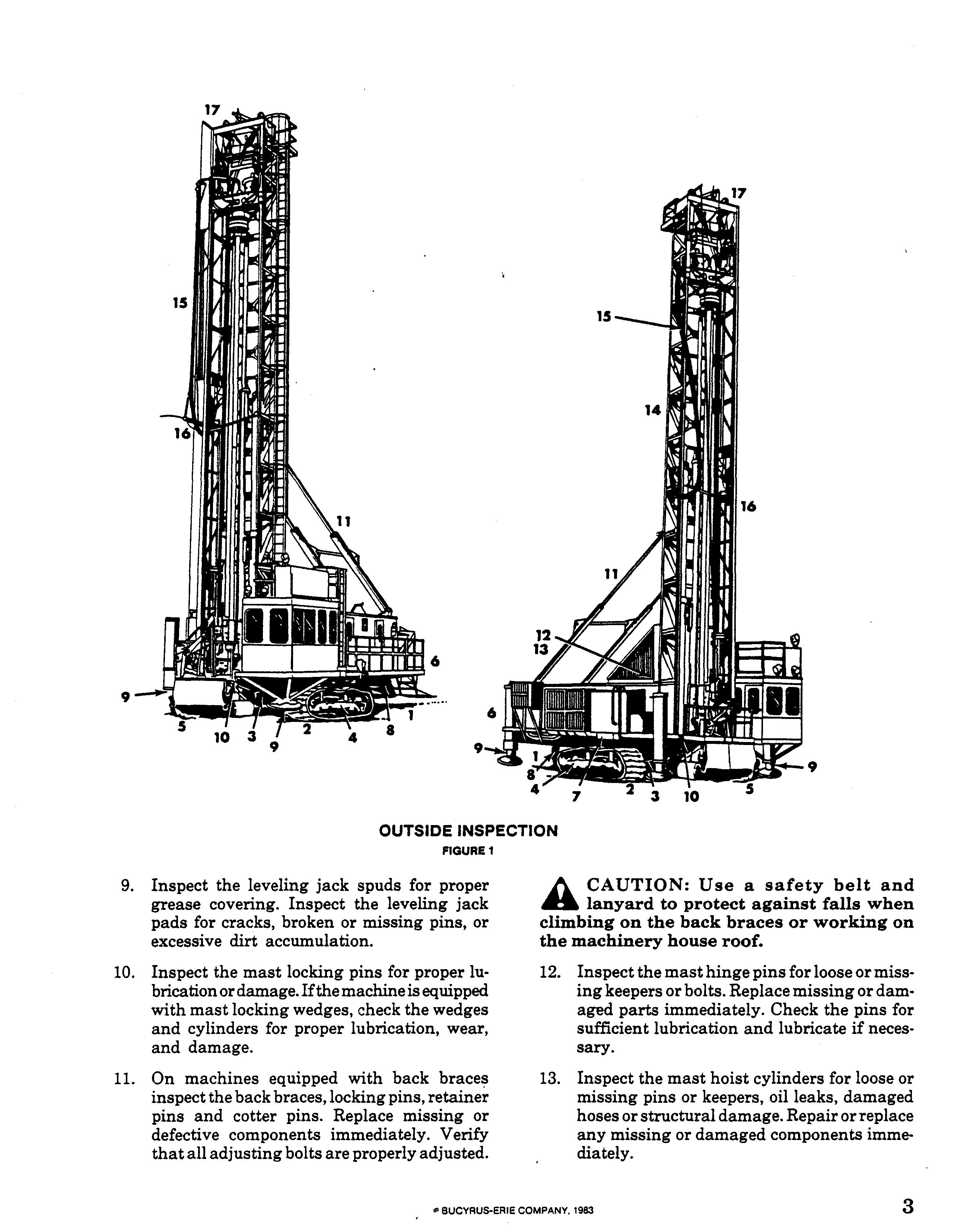
11. On machines equipped with back inspect the back braces, locking pins, retainer pins and cotter pins. Replace missing or defective components immediately. Verify that all adjusting bolts are properly adjusted.
h CAUTION: Use a safety belt and lanyard to protect against falls when climbing on the back braces or working on the machinery house roof.
12. Inspect the mast hinge pins for loose or missing keepers or bolts. Replace missing or damaged parts immediately. Check the pins for sufficient lubrication and lubricate if necessary.
13. Inspect the mast hoist cylinders for loose or missing pins or keepers, oil leaks, damaged hoses or structural damage. Repair or replace any missing or damaged components immediately.
14. Inspect the mast structure for bent or broken chords or lacings, loose or broken parts, proper rack lubrication or excessive rack wear. Inspect ladders, handrails and platforms for broken or missing parts. Repair or replace broken or missing parts immediately. Verify that the mast stops on the mainframe are in place.

15. Check the main air flex hose, grease lines, and electric lines running from the mast to the rotary drive unit for interference With the mast or excessive wear or leaks.
16. Check the safety restraint cables on the mast. Be certain that the cables and supports are in good repair with no cracks, missing or loose hardware or any damage that could affect their effectiveness.
17. Every 160 hours inspect and lubricate the upper chain sprockets and auxiliary reel sheaves. All pins, keepers and hardware should be secured tightly.
1. Check the oil level in the auxiliary air compressor. Add oil to the proper level if necessary. Check the drive belts for proper tension, excessive wear or broken belts. Verify proper adjustment when new belts have been installed.
h CAUTION: Do not remove the belt ... guard unless the air compressor switch in the operator's cab has been turned off and the breaker on the control cabinet in the machinery house has been turned off and tagged. Serious injury could result if the compressor should start while servicing the compressor belts.
2. During freezing weather add alcohol to the antifreezer (if so equipped).
h CAUTION: Serious personal injury .. will result if the fill plug of the antifreezer is removed with pressure in the system. Relieve all pressure from the air system and' shut off the air compressor before servicing this unit.
h CAUTION: Alcohol is flammable. Do .. not use alcohol while smoking or near possible ignition sources. Consult the alcohol distributor for specific safety precautions. Store alcohol in an approved metal container outside of the machinery house.
3. Check the tension on the drive belts of the main air compressor. Check the belts for cracks or wear.
h CAUTION: Do not remove guard unless the control power breaker in the machinery house has been locked in an offposition and the compressor test started to verify that the compressor will not start. Serious personal injury will result if the compressor starts while the drive belts are being serviced.
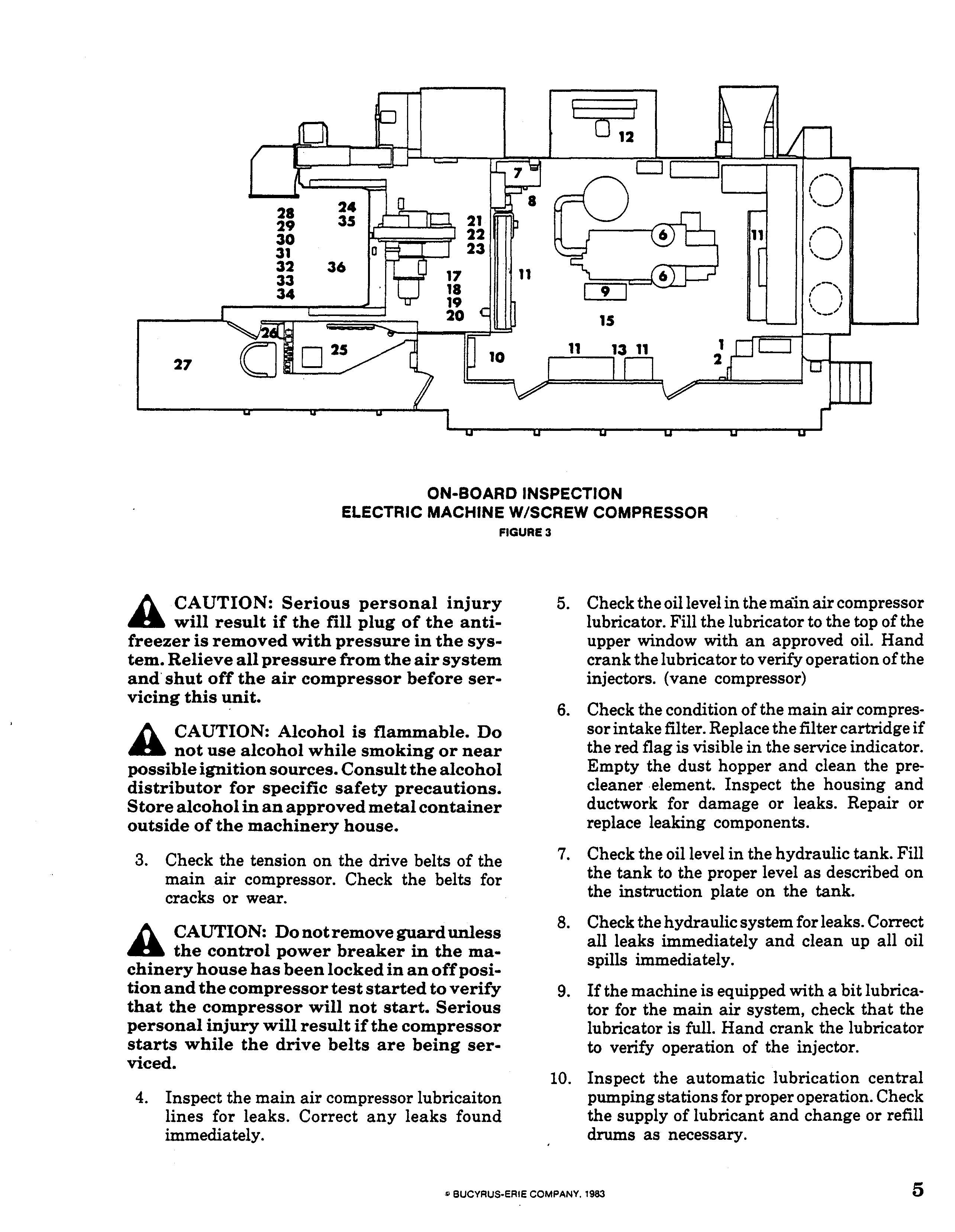
4. Inspect the main air compressor lubricaiton lines for leaks. Correct any leaks found immediately.
5. Check the oil level in the main air compressor lubricator. Fill the lubricator to the top of the upper window with an approved oil. Hand crank the lubricator to verify operation olthe injectors. (vane compressor)
6. Check the condition of the main air compressor intake filter. Replace the filter cartridge if the red flag is visible in the service indicator. Empty the dust hopper and clean the precleaner element. Inspect the housing and ductwork for damage or leaks. Repair or replace leaking components.
7. Check the oil level in the hydraulic tank. Fill the tank to the proper level as described on the instruction plate on the tank.
8. Check the hydraulic system for leaks. Correct all leaks immediately and clean up all oil spills immediately.
9. If the machine is equipped with a bit lubricator for the main air system, check that the lubricator is full. Hand crank the lubricator to verify operation of the injector.
10. Inspect the automatic lubrication central pumping stations for proper operation. Check the supply of lubricant and change or refill drums as necessary.
11. Close and lock all electrical cabinet doors.
h CAUTION; Assume all parts inside of .. the electrical cabinets to be energized. All electrical components should be serviced by qualified electrical personnel only.
12. Inspect the compressor radiator and fan. Check for signs of deterioration or damage to hoses,valves, fitting, etc. Check for leaks at all joints. Check the radiator core for blockage by dust, dirt, leaves, paper, etc. and clean as necessary.
13. Check the phase sequence indicator light. If the lamp is not lit contact'qualified electrical service personnel before starting the machine.
14. For diesel powered machines conduct the prestart inspections as required by the engine manufacturer.
15. Inspect the machinery house for general cleanliness. Clean all dirt and debris from the machinery house.
WARNING; Do not use compressed air to clean the machinery house. Compressed air will only move the dirt around. Use a vacuum cleaner to remove the dirt from the machine. Failure to clean the inside of the machinery house will cause damage to many of the components located there.

16. Check the coolant level in the air compressor radiator. Add coolant as required to fill the radiator.
h CAUTION; Due to the location of the .. radiator compartment handrails can not be placed on the compartment roof. Use a safety belt and lanyard to protect against falling from the compartment roof. Remove the radiator cap slowly and use suitable protection against escaping steam to prevent serious injury.
17. Inspect the auxiliary reel, auxiliary reel brake and auxiliary reel line.
18. Check the oil level in the hoist-propel gearcase. Fill with recommended oil to the proper level.
19. Inspect the hoist brake for proper adjustment, excessive band wear, proper band alignment, loose or broken linkage, missing keeper pins, etc. Repair or replace missing or damaged parts immediately.
20. Inspect the pulldown chains and sprockets for bent or missing links, proper lubrication, proper timing and excessive wear or dirt buildup.
21. Inspect the intermediate propel chains for proper adjustment, bent or broken links, or excessive wear or dirt buildup.
22. Inspect the propel brakes for proper adjustment, excessive band wear, loose or broken linkage, missing keeper pins, etc. Repair or replace missing or damaged parts immediately.
23. Inspect the area around the hoist-propel gearcase for oil, grease or air leaks or other missing or damaged equipment.
24. Inspect the pulldown chain equalizer cylinder for leaks or damage. Make sure that the ram has not extended to the maximum stroke of6
inches. If the ram is bottomed out, the pulldown chains will have to be shortened before starting the drill.
25. Inspect the area behind the operator's panel for oil, air or water leaks.

26. Check all controls for free operation. Return all controls to the "off' or "set" position.
27. Inspect the operator's cab for housekeeping and cleanliness. Clean dirt and debris from the cab. Clean the windows to give full visibility for p.roper operation.
WARNING: Do not use compressed air to clean the operator's cab. Compressed air will only move the dirt around. Use a vacuum cleaner to remove the dirt from the cab.
28. Inspect the tool wrenches for free operation, broken or missing parts, proper lubrication, oil leaks or dirt accumulation. Repair or replace parts as necessary and clean the drilling platform.
h CAUTION: Before working near or .. under the rotary drive unit, make sure all of the operator's controls are off and tagged and the hoist brake set to prevent movement of the unit. Serious personal injury or death could result should the rotary drive unit fall when personnel are working near or under it.
29. Inspect the casing tong and breakout cylinder for free operation, broken or missing parts, proper lubrication, oil leaks or excessive dirt accumulation. Repair or replace parts as necessary. Be certain that the breakout cylinder is stored properly out of the way of the rotary gearcase and fully retracted. Be certain that the casing tong is secured out of the way.
30. Inspect the tool racks for broken or missing parts, proper operation, dirt accumulation, or oil leaks. Be certain that the pipe gate is closed and that the rack is in the retracted position and locked.
31. Inspect the guide bushing for excessive wear or dirt accumulation. Also inspect the retainer lugs to be sure they are intact. Do not operate the machine without both retainer lugs intact and securely welded to the deck.
32. Inspect the tool string for excessive wear, dirt accumulation, bent pipe and secure joints. The bit cones and bearing should be in good condition. Manually turn the cones to make sure they turn freely.
33. Inspect the rotary gearcase for oil leaks, damaged lines, dirt accumulation and other damaged or missing parts. Check the oil level in the gearcase. Fill to the recommended level with an approved gear oil. Check the rotary motor ventilation inlets for leaves, paper, rags, etc. blocking the flow of air.
34. Inspect the rotary drive unit for excessive wear or dirt accumulation. Also inspect the pulldown sprockets for excessive wear. Inspect the rack pinions for excessive wear, proper lubrication, and tight retainer bolts.
Inspect the slide shoes for proper adjustment and excessive wear. Check for loose or missing bolts and bent or cracked structural members.
35. Inspect the equalizer sprockets for free operation, proper lubrication, excessive wear, and loose or missing hardware.
36. Check the dust or chip deflector for loose or missing parts, excessive wear or dirt accumulation. The deflector should seal around the drill pipe securely.
Lubrication of the 45-R blast hole drill is extremely important. Most drills come equipped with automatic lubrication systems that lubricate most of the necessary points at regular intervals. These systems, although automatic, are not foolproof. Broken lines, dirty lubricant, faulty feeders, and a whole range of other problems can cause wearing parts to loose lubrication. For this reason, it is important that all lubrication points be inspected every shift to verify that they are receiving lubrication. Also, there are several points for lubrication that either need lubrication very infrequently, or are not possible to pipe into the automatic system. These points will need lubrication applied manually.
The lube charts in the appendix give the location and frequency of lubrication.
The lubricant used should be kept clean. If possible the lubricant should be supplied in unopened containers. Be careful when changing containers on the automatic system to keep the pump and drum cover clean.
When using a manual gun wipe each fitting and the grease gun fitting before injecting the lubricant. Use clean containers and funnels for oils and grease for transferring to the gearcases or reservoirs. Do not allow water to enter any gearcase, oil reservoir or container. Wipe off all fill caps before removing them.
Regardless of previous experience, the new operator of any machine must become familiar with the location and function of all of the operating controls before he can begin to operate the machine. Since this manual covers all possible controls that • could be used on the 45-R drill, he should familiarize himself with both this manual and the particular machine being operated.

For the purpose of this manual, the operating controls have been divided into three groups, depending upon their location. These three groups are:
1. Operator's Console Controls
2. Machinery House Controls
3. Miscellaneous Controls
h CAUTION: Read and become familiar .. with this manual before attempting to operate any of the machine controls. Pay particular attention to the caution and warning statements, andany federal, state, local or company safety rules relating to the machine. Failure to be aware of and understand the hazards associated with the operation of the controls may lead to death, personal injury or serious machine damage.
WARNING: All of the hydraulic controls (1 through 13), with the exception of the hoistpulldown selector (5), will automatically return to the neutral position when released. This is a safety feature and should not be used during normal operation. The controls should be moved from and returned to the neutral position slowly. Failure to operate the controls smoothly will lead to machine damage.
The leveling jack controls are used to raise or lower the leveling jacks at the four corners of the machine. There are four controls, one for each leveling jack.
Pulling the control toward the operator will lower the jack, raising the machine. Pushing
the control away from the operator will raise the jack, lowering the machine. Returning the control to neutral will stop all motion. Full forward or rearward positions provide the fastest motion.
The hoist-pulldown selector is used to hydraulically hoist or lower the rotary drive unit or auxiliary reel line.
This control,is a full flow locking type in that it cannot be feathered like the other hydraulic controls. Detents will lock the spool in push (pulldown), pull (hoist) or neutral positions. This feature allows the operator to have the control activated without having to continuously hold it in the activated position.
Pushing the control away from the operator will lower the rotary drive unit or auxiliary reel line. Pulling the control toward the operator will hoist the rotary drive unit or auxiliary reel line.
The tool rack controls are used to raise or lower the tool racks. The number of tool rack controls is determined by the number of tool racks on the machine. There is a separate control for each rack. All of the controls operate identically.
Pulling the control toward the operator will raise the tool rack while pushing the control away from the operator will lower the tool rack. Full forward or rearward positions will provide the fastest motion.
The casing tong control is used to extend or retract the casing tong breakout cylinder.
Pulling the control toward the operator will extend the casing tong breakout cylinder. Pushing the control away from the operator will retract the casing tong cylinder. Full forward or rearward positions will provide the fastest motion.
The tool wrench control is used to clamp or release the tool wrench from the tool string.


Pushing the control away from the operator will extend the wrench, clamping the tool string. Pulling the control toward the operator will retract the tool wrench, releasing the tool string. Full forward or rearward positions provide the fastest motion.
The dust curtain control is used to raise or lower the dust curtains.
Pushing the control away from the operator will lower the dust curtain. Pulling the control toward the operator will raise the dust curtain. Full forward or rearward positions will provide the fastest motion.
WARNING: To eliminate shock loading on the mast structure the mast hoist control should be moved a way and returned to the neutral position slowly.
The mast hoist control is used to raise or lower the mast.
Pulling the control toward the operator will raise the mast. Pushing the control away from the operator will lower the mast. Full forward or rearward positions provide the fastest motion.
The mast latch control is used to secure the mast in the raised vertical position or release the mast so that it can be lowered.
Pushing the control away from the operator will unlatch the mast allowing it to be lowered. Pulling the control toward the operator will move the latch to lock the mast in the vertical position. Full forward or rearward positions provide the fastest motions.

The center guide control is used to open or close the center guide jaws around the pipe.
Pushing the control away from the operator will close the jaws around the drill pipe. Pulling the control toward the operator will open the jaws. Full forward or rearward positions provide the fastest motion.
The downfeed pressure control regulates the pressure in the pulldown hydraulic circuit. The pulldown force is determined by how far the control knob is turned. Turning the knob fully to the left (counter-clockwise) will relieve the pressure in the circuit, resulting in no pulldown force. As the knob is turned to the right (clockwise) the pulldown force will increase to the maximum at the full clockwise position of the knob.
NOTE: In order to turn the knob it is necessary to first pull the knob out slightly to unlock it. Releasing the knob will return it to the locked position.
The hoist brake control is used to set or release the hoist brake.
Pulling the control lever fully toward the operator will completely set the hoist brake preventing movement of the rotary drive unit. As the control is pushed away from the operator, the brake is gradually released until it is fully released at the full forward position.
When in the lowering mode, the lowering speed of the rotary drive unit is determined by how far the control lever is pushed forward from the set position. Full forward will release the brake fully, resulting in the fastest lowering speed.
WARNING: The hoist brake must be fully released when hoisting or lowering the rotary drive unit with power. Partial releasing of the brake is allowed only when lowering under gravity.
The auxiliary reel brake control is used to set or release the auxiliary reel brake.
Pulling the control lever fully toward the operator will completely set the brake, preventing movement of the auxiliary reel line. As the control is pushed away from the operator, the brake is gradually released until the brake is fully released at the full forward position.
The lowering speed of the auxiliary reel line when in the gravity lowering mode is deter-
• Thank you very much for reading the preview of the manual.
• You can download the complete manual from: www.heydownloads.com by clicking the link below
• Please note: If there is no response to CLICKING the link, please download this PDF first and then click on it.