
Technical Manual
• Thank you very much for reading the preview of the manual.
• You can download the complete manual from: www.heydownloads.com by clicking the link below
• Please note: If there is no response to CLICKING the link, please download this PDF first and then click on it.

GENERAL OPERATING INSTRUCTIONS

How to operate a power excavator efficiently must be learned in much the same way as any skilled trade.. No one is a "bornll operator. Regardless of previous experience, the new opera,tor must use care to operate the machine safely so as not to endanger men or equipment.
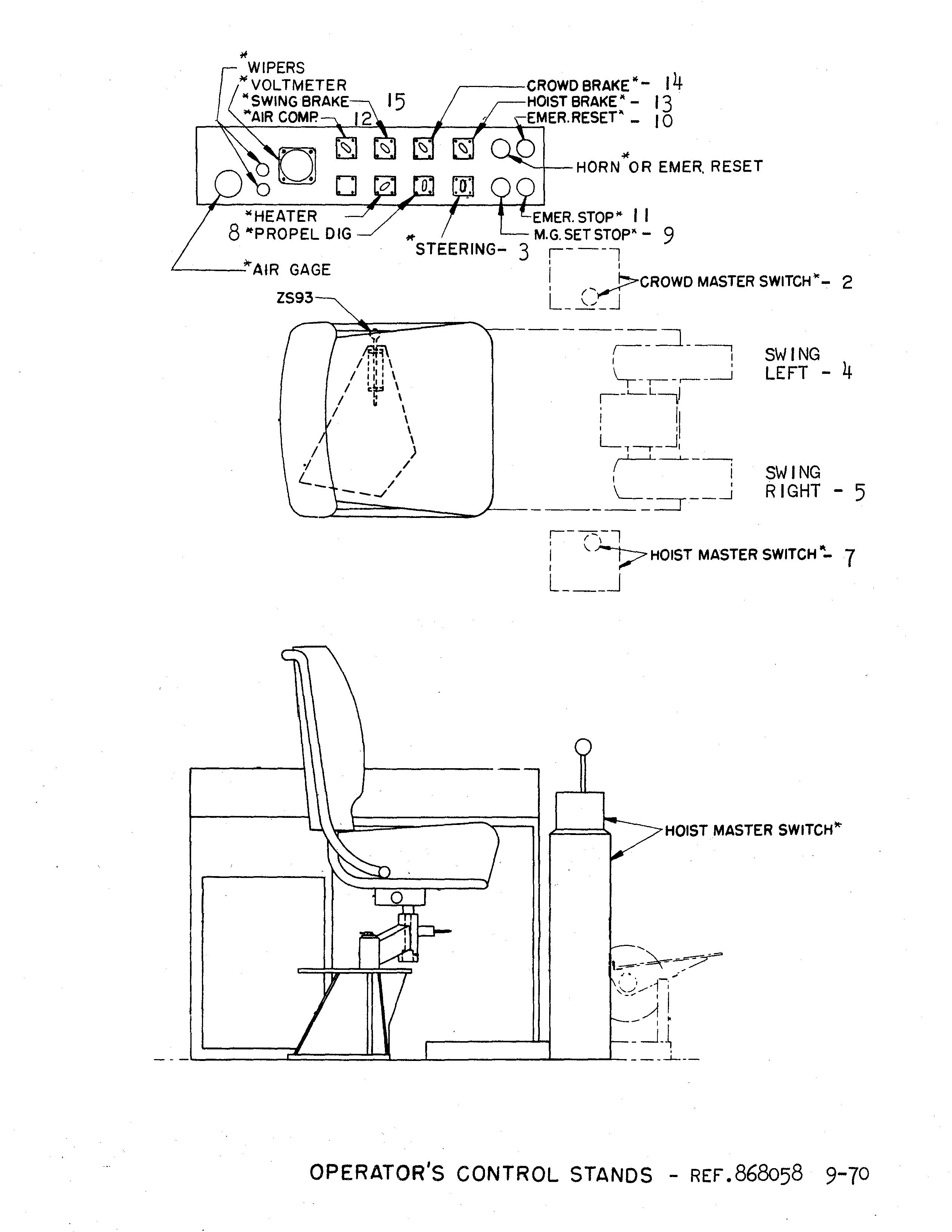
At first glance the large number of levers and switches looks as though operating the machine might be complicated, but most of them control some auxiliary function of the machine such as steering, etc., and are not used in the regular operating cycle. The two tall levers and the two pedBJ.s in front of the operator are the principaJ.controls used in the regular operating cycle and their use will be described in detail further on in these instructions. The first thing the new operator must do is to familiarize himself with the purpose of each of these levers and operating switches.
When learning to operate the machine it is a good plan to study each separate function until fully familiar wi ththe control of all the aUXiliary functions of the machine such as propelling, steering, etc , then try out the main controls which are used in actual digging operations. The main functions can be tried separately until the operator becomes accustomed to the response of the machine to the controls.
When learning to handle the controls be sure there is plenty of clearance and no danger spots around the machine such as overhead wires, culverts, ditches or embankments.
A. INSPECT MACHINE BEF'ORE STARTING SHIFT
Before beginning to ope;rate the machine at the start of a shift, make a general inspection of the machine to make sure it is ready for operation:
Look under the cats and around the machinery to see if there is any evidence of lubricating oil leaks. Correct any major leaks and refill to required level. Make a note of minor leaks and correct at first opportunity possible.
Look over the electrical accessories to make sure all units are securely mounted and properly adjusted.
Lubricate all twice-a-shift (4 hour) and once-a.-shift (8 hour) points as covered in the lubrication section of this instruction book. Consult the lubrication record for the machine and service all points which have gone the specified length of ,time since the last previous servicing.
Check operation of all hand levers and foot pedals to see that they work freely without binding, yet with n0 lost motion.
Check main line air pressure which must be at least 110 lb. sq. inch. Engage the clutches to check operation of each m0tion.
B. POINTS TO WATCH DURING SHIFT
During the shift, watch for any signs of improper operation or adjustment. The following items are of particular importance:
any any any or failure to respond.
1. Check generator, motors and gears for any unusual noise, loss of power or failure to respond.
1. 2. 3. 4. 5. 6. 7.2. Check the clutches immediately if they should start to slip excessively during normaJ. operation.
3. Watch the cables to see that they do not become crossed on the drums .
4. When propelling check the tracking of the drive tumblers on the cat links and, if necessary, readjust the belts to correct improper operation.
5. When operating auxiliary functions such as the steering clutches, etc., note any tendency of the controls to "hang up" or jam which would indicate improper operation. Correct the adjustment at the earliest possible opportunity.
2. during operation. cat links and, if readjust the belts to correct improper operation. note to or Correct the at the earliest opportunity.

6. Watch the air gauge in the operator's cab and investigate immediately should there be a sudden drop in air pressure.
C. CHECK MACHINE AT END OF SHIFT
6. Watch the air in the cab and investigate immediately the end of the shift the machine again for evidence of excessive which have occurred the shift.
At the end of the shift go over the machine again for evidence of excessive wear or damage which may have occurred during the shift.
2.
5.
Examine all cables carefully for broken strands or other evidence of weakness. Arrange to replace weakened cables before starting another shift. Clean out carefully any grease or dirt which may have accumulated around the machinery during the shift. Clean out excessive nru.d or dirt in the cat belts. This is particularly important in freezing weather. Put planks, brush or dry material under cats before shutting down machine if it is likely to freeze. If the machine is to be idle for several hours, move it away from a high bank where it might be damaged by a slide or falling rocks. Do not leave the machine in a low spot where there is any danger of flooding. Let the dipper down to the ground, be sure all brakes are set and place all controls in neutral position. Close the windows at the operator's position and lock all cab doors.
or to Clean out carefully or dirt which have accumulated around out cat weather. Put brush or material under cats before shutting down machine if it is likely freeze. the machine is to be idle for several move from bank where it might be damaged by slide falling rocks. leave a Let to all set at
STARTING INSTRUCTIONS
The starting equipment usually furnished consists of initial starting covering Equipment in
The motor generator set starting equipment usually furnished consists of an across-the-line oil circuit breaker. Special installations may have push button start and/or a double throw oil circuit breaker and an auto transformer.
Before initial starting of machine read Sect.ion covering Care and Maintenance of Electrical Equipment and the electrical manufacturer's bulletins included in another book for proper starting procedure of oil circuit breaker and maintenance of elect.rical equipment.
The direction of rotation of M.G. set. should be Checked on initial start and anytime thereafter when the cable has been removed from machine, or line trouble has been encountered. It is a good practice to number or letter the plugs and jacks to avoid difficulty.
The air compressor should be started as soon as possible so that sufficient pressure may be built up to operate brakes and clutches.
The emergency reset button should t.hen be depressed, this supplies D.C. current for the operation of the brake and clutch magnet valves and the control field of the rotating control Units. It will be necessary to have hoist blower motor operating and oil circuit breaker in before contactor will close.
The direction of rotation of should be Checked initial and or It to compressor possible emergency D.C. operation magnet operating in
2. 3. 4. 5. 6.OPERATING
SHOVEL OPERATING INSTRUOI'IONS

Snap, hoist, swing and crowd brake switches to off position. This energizes brake magnet valves and allows air to enter brake cylinder releasing brake.
A. SWINGING
Swinging machine to right or left is controlled by the two foot pedals located in the front center section of operator l scab.
1. To swing to the left - depress left pedal.
Snap, and crowd brake position. magnet allows air enter cylinder to or left two located front center section to left left the right pedal.
2. To swing to the right - depress right pedal.
The rate of swing can be controlled by varying the amount the pedal is depressed. To bring machine to a stop depress the opposite pedal. The braking effect can also be varied by the amount the pedal is depressed. This is called "plugging" and may be done as rapidly and as frequently as is required for safe operation.
of swing be controlled amount the pedal bring machine effect by the is depressed. This "plugging" rapidly as operation.
The swing brake should not be used for stopping machine when in motion except in an emergency. The brake should only be used when machine is at rest.
B. HOlffilING
The hoisting and lowering motion is controlled by the tall upright lever to the right of the operator.
brake in an emergency. The should used when and lowering the tall to right Place Dig enter Clutch).'
1. Place the "Propel-Dig" switch in the Dig position. (This allows air to enter Hoist Clutch).'
2. To hoist - push lever forward.
3. To lower - pull lever back.
The of hoisting and lowering can be controlled by varying the distance the lever is pushed forward or pulled back from the neutral position. To stop or change direction all that is required is to change direction of the lever or "plug" and bring dipper to a stop.
2. To To pull hoisting and controlled varying pushed forward back from the that the lever dipper to
The hoist brake should not be used during operation of shovel except during an emergency, when machine is idle or to hold dipper in the air.
brake be used operation shovel except an is to
The horn is operated by a latch mounted on the hoist lever.
C. CROWD
operated by a latch the lever. CROWD
Be sure that crowd clutch air pressure falls within range on the instruction plate mounted near crowd clutch air gauge.
The crowd motion is controlled by the tall upright lever to the left of operator.
Be sure that crowd clutch air range gauge. is by to left of To push forward.
1. To crowd out - push lever forward.
2. To retract or crowd in - pull lever back.
2. To retract or pull lever
The rate and retracting controlled forward pulled back from position. To change or
The rate of crowding and retracting can be controlled by varying the distance the lever is pushed forward or pulled back from the neutral position. To stop or change direction move lever in opposite direction or "plug".
V_,
V_,
The crowd brake should not be used during operation of shovel except in an emergency or when the machine is idle.
D. DIPPER TRIP
The is latch handle mounted on the crowd lever
boom lower section.
The dipper trip is operated by a latch handle mounted on the crowd lever and controls a variable torque motor, driving suitable reduction gearing and associated rope drum, mounted as a unit on the right hand leg of the boom lower section.
1. Depress the latch handle to dump dipper.
2. The dipper door will latch when the dipper is lowered.
E. PROPELLING
E. PROPELLING
The motion is controlled the hoist motion lever.
The propelling motion is controlled by the hoist motion lever.
1. Snap hoist, swing and crowd motion brake switches to the on position.
2. Place "Propel-Dig" switch in propel position.
3. Place propel brake switch in off position.
2. Place switch Place propel brake switch in off position.
4. (a) To move forward, with driving tumblers to the rear, pull hoist lever back.
(b) To move backward, push hoist lever forward. Motion can be stopped by plugging and returning controller to neutral.
F. STEERING CONTROLL FROM OPERATOR'S POSITION (See Schematic Arrangement of Air Piping and General Arrangement of Steering Machinery Drawings.)
Full steering control from the operator's cab, and with the revolving frame in any position, is obtained by clutch-shifter cylinders mounted in the truck frame which are controlled by a valve lever at the operator's left.
Air under pressure, for operation of the clutch cylinders, is obtained from the compressor mounted on the left side of the revolving frame. Three concentric pipes, with a six way swivel connection at the upper end and carry the air through the center of rotation to the left-hand and right hand clutch-shifter cylinders and the digging-brake operating cylinder in the truck frame.
Admission of air to the clutch shifter cylinders is controlled by a valve mounted on the wall to the operator's left in the operator's cab.
(b) push operator's in any position, is obtained by clutch-shifter cylinders mounted in the truck at carry to on operator's operator's
To turn to the left with driving tumblers to the rear, move the valve handle forward. This admits air pressure to the left-hand cylinder in the base and overcomes the spring to move the clutch to the locked position. It may be necessary to move the machinery slightly with the hoist controller in order to disengage the steering clutch. Moving the left-hand steering clutch to the locked position locks the left cat belt and when power is applied a sharp turn may be made.
Turn to the right are made by moving the handle to the rear, otherwise the sequence of operation is the same as for turns to the left.
overcomes to move to may necessary machinery slightly in power turn be made. Turn to to sequence same as
In either case the clutch is returned to the engaged position by spring pressure when air pressure is released from the system by moving valve lever to neutral or center position to exhaust air fr0m lines. It may be necessary to move the machinery slightly with the hoist controller in order to re-engage the clutch.
In to when air pressure is released from the system by moving valve lever neutral position exhaust air fr0m lines. It may be necessary the to re-engage

DRAGLINE OPERATING INSTRUCTIONS

INSTRUCTIONS
hoist., and drag off posit.ion. This allows air t.o brake cylinder
Snap hoist., swing and drag brake swit.ches t.o off posit.ion. This energizes brake magnet.vaJ.ves and allows air t.o ent.er brake cylinder releasing brake.
A. SWINGING
SWINGING
Swinging machine t.o right. or left. is cont.rolled by t.he t.wo foot. pedals locat.ed in t.he front. cent.er sect.ion of operat.or' scab.
Swinging machine or cont.rolled by t.he t.wo in front. operat.or' scab.
1. To swing t.o t.he left. - depress left. pedal.
2. To swing t.o t.he right. - depress right pedal.
The rat.e of swing can be cont.rolled by varying t.he amount. t.he pedal is To bring machine t.o a st.op depress t.he opposi t.e pedal. The braking effect. can also be varied by t.he amount. t.he pedal is depressed. This is called "plugging" and may be done as rapidly and as frequent.ly as is required for safe operat.ion.
1. swing t.he - left. pedal. t.he - right rat.e cont.rolled varying t.he amount. pedal is a effect. also be t.he and may and as required
The swing brake should not. be used for st.opping machine when in mot.ion except. in an emergency. The brake should only be used when machine is at. rest..
B. DRAG
The drag mot.ion is cont.rolled by t.he t.all upright. lever t.o the left. of t.he operat.or.
The swing brake should not. be st.opping when in mot.ion in brake only is at. mot.ion is by t.he t.all t.o left. of t.he
1. Place t.he "Propel-Dig" swit.ch in t.he Dig posit.ion. (This allows air t.o ent.er Drag Clut.ch).
Place t.he "Propel-Dig" swit.ch in posit.ion. (This ent.er Drag
2. To payout. - push lever forward.
3. To drag in - pull lever back.
2. To - push To lever
l'he ra:te of dragging in and paying out. can be cont.rolled by varying the dist.ance t.he le:ver :Ls pushed forward or pulled back from t.he neut.ral posit.ion. To st.op or change direct.ion .all t.hat. is reqUired is t.o change direct.ion of t.he lever or "plug" and bring bucket. t.o a st.op.
l'he ra:te be by varying back from t.he neut.ral To st.op change .all t.hat. t.o and bucket. t.o st.op.
The not. be operat.ion eXCept. an is t.o bucket. in air.
The drag brake should not. be used during operat.ion of dragline eXCept. during an energency, when machine is idle or t.o hold bucket. in t.he air.
C. HOIsr
The hoist. mot.ion is cont.rolled by t.he t.all upright. lever t.o the right. of operat.or.
1. To hoist. - push lever forward.
2. To lower - pull lever back.
The by lever the operat.or. lever lower lever cont.rolled t.he the lever is pushed forward or from posit.ion. To st.op
The rate of hoist.ing and lowering can be cont.rolled by varying t.he dist.ance the lever is pushed forward or pulled back from t.he neut.ral posit.ion. To st.op or change direct.ion move lever in opposit.e direct.ion or "plug".
The be uSed operat.ion dragline in when
The hoist. brake should not. be uSed during operat.ion of dragline except. in an emergency or when machine is idle.
The operat.ed by a mount.ed
The horn is operat.ed by a lat.ch mount.ed on t.he hoist. lever.
the right clutch shifter lever to the outside. This disengages the clutch and allows the right hand cats to free wheel when power is applied as described under Propelling. The opposite applies in turning to the left using the left clutch lever.
clutch shifter the This clutch allows the cats to free wheel power is under The in turning left the
2. order to use the locked steering it is necessary to move the steering so engages jaws to cat frames. The clutch pinned to the clutch guard before starting to propel. disengage the clutch it may be necessary to relieve the on momentarily the "When with either ground must the side ride over or turn into a rock which may be projecting from the floor of the would ·links frames.
2. In order to use the locked steering it is necessary to move the steering clutch manua.lly so that it engages with the locking jaws which are welded to the cat side frames. The clutch lever should be pinned to the clutch guard before starting to propel. To disengage the clutch it may be necessary to relieve the load on the jaws by momentarily reversing the controller. "When steering the machine with either clutch in the locked position, the ground man must be very careful so as not to allow the side frames to ride over or turn into a rock which may be projecting up from the floor of the quarry. To do so would place dangerous stresses in the ·links and side frames.
DRAGUNE OPERATING HINTS
Actual digging operations with the dragline require coordination between the hoist and drag motions which may be a little difficult to attain. Attention to the following and a little practice will soon give the operator the knack of filling the dragline bucket smoothly and quickly and permit accurate dumping.
Actual digging with the dragline require between the and drag motions which may be a little difficult to attain. Attention to the following little soon the bucket and and permit dumping.

l. Keep the boom angle as high as conditions will permit so as to provide maximum stability. Do not exceed figures given in the machine specifications.
Keep the boom conditions so imum stability. Do not exceed figures given in the machine specifications.
2. Regulate the depth of cut by taking in or pa;y1ng out hoist line.
3. Hoist the bucket out of the pit as soon as it is full and before dirt is pushed up against the machine.
2. Regulate depth taking in out hoist Hoist of pit as as pushed the
4. start and stop the swing motion slowly so as not to place unnecessary strain on the boom.
4. start stop swing as not to place unnecessary strain the boom.
5" "When dropping back into the pit be careful to check the hoist and drag drums with the controllers so that the cables do not run off the drams.
5" back pit careful hoist and the cables off drams.
machine press control panel. cuts off D.C. brakes, rotating control units magnet are sure return to
To stop machine press "Emergency Stop" button on control panel. This cuts off all D.C. current to brakes, rotating control units and clutch magnet valves. Thus all brakes are applied and controls made inoperative. Be sure to return controls to neutral.
To stop Motor-Generator Set depress button marked I'Ma stop" on control panel.
To stop Motor-Generator depress marked on control panel.
CONTROL OF BRAKE AND CLUTCHES - SHOVEL
I. Control of Brakes
All brakes are controlled by means of switches located in the cab panel in the operator I scab.
Flipping the switch to the "off" position energizes the magnet valve which in turn allows air to enter the brake cylinder and thus releasing the brake. If the magnet valve is de-energized by power failure, by opening the brake switch, or if a broken air line caused loss or pressure, the brake shoes are set by spring pressure.
power failure, switch, set
The hoist brake, as are all others, is separately controlled by the snap switch marked "Hoist Brake" in the panel at the operator's right. If the loaded dipper is held extended or the hoist line is otherwise under load when shifting from hoist to propel, it is a good plan to set the brake by means of the IIHoist Brake" snap switch before snapping the "Dig-Propel switch to the propel position. The swing and crowd brake are controlled by the switches marked "Swing Brake" and "Crowd
II. Control of Clutches
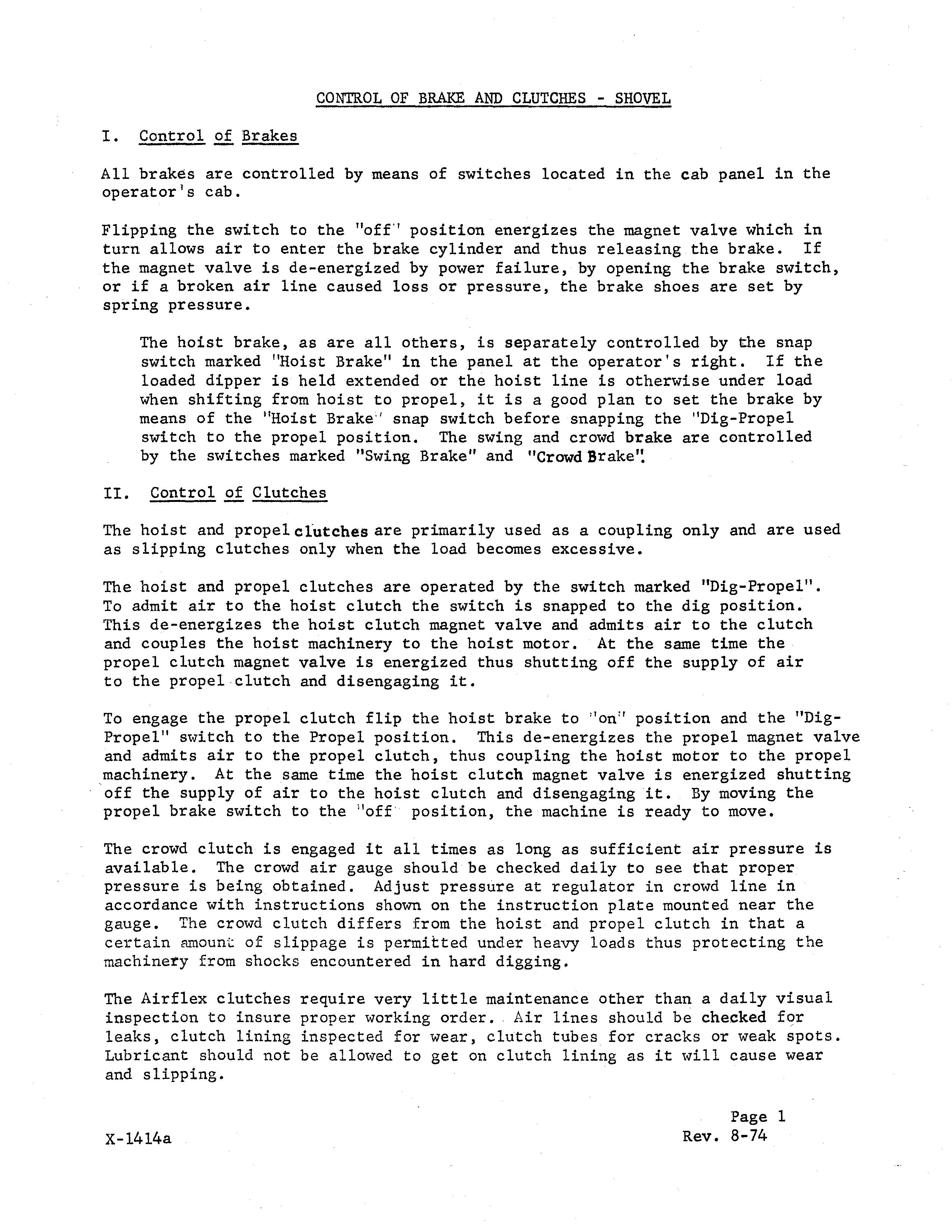
The hoist and propel clutches are primarily used as a coupling only and are used as slipping clutches only when the load becomes excessive.
The hoist and propel clutches are operated by the switch marked "Dig-Propel". To admit air to the hoist clutch the switch is snapped to the dig position. This de-energizes the hoist clutch magnet valve and admits air to the clutch and couples the hoist machinery to the hoist motor. At the same time the propel clutch magnet valve is energized thus shutting off the supply of air to the propel clutch and disengaging it.
The hoist brake, all others, is separately controlled by the snap switch to the propel position. The swing and crowd brake are controlled to to de-energizes magnet to the clutch and it.
To engage the propel clutch flip the hoist brake to "on" position and the "DigPropel" s'tvitch to the Propel position. This de-energizes the propel magnet valve and admits air to the propel clutch, thus coupling the hoist motor to the propel machinery. At the same time the hoist clutch magnet valve is energized shutting off the supply of air to the hoist clutch and disengaging it. By moving the propel brake switch to the "off position, the machine is ready to move.
The crowd clutch is engaged it all times as long as sufficient air pressure is available. The crowd air gauge should be checked daily to see that proper pressure is being obtained. Adjust pressure at regulator in crowd line in accordance with instructions shown on the instruction plate mounted near the gauge. The crowd clutch differs from the hoist and propel clutch in that a certain ffmount of slippage is permitted under heavy loads thus protecting the machinery from shocks encountered in hard digging.
The Airflex clutches require very little maintenance other than a daily visual inspection to insure proper working order. Air lines should be checked for leaks, clutch lining inspected for wear, clutch tubes for cracks or weak spots. Lubricant should not be allowed to get on clutch lining as it will cause wear and slipping.
To the clutch the hoist brake to "on" and the magnet to to certain ffmount of slippage is permitted under heavy loads thus protecting the in very a to insure order. lines should be checked for I
X-l4l4a
Rev. 8-74
CONTROL OF BRAKES AND CLUTCHES - DRAGLINE
CONTROL OF BRAKES AND CLUTCHES - DRAGLINE

The hold brake, as are all others, is separately controlled by the snap switch marked "Hold-Brake ll in the panel at the operator I s right. If the loaded bucket is held suspended or the holding line is otherwise under load when shifting from drag to propel, it is a good plan to set the brake by means of the "Hold Brake" snap switch before snapping the "Dig Propel " switch to the propel position. The swing and close brake are controlled by the switches marked "Swing-Brake" and lIClose-Brakel'.
The hold brake, as are all others, is separately controlled by the snap switch marked "Hold-Brake ll in the panel at the operator I s right. If the loaded bucket is held suspended or the holding line is otherwise under load when shifting from drag to propel, it is a good plan to set the brake by means of the "Hold Brake" snap switch before snapping the "Dig Propel " switch to the propel position. The swing and close brake are controlled by the switches marked "Swing-Brake" and lIClose-Brakel'.
The hold and propel clutches are primarily used as a coupling only and are used as slipping clutches only when the load becomes excessive.
The hold and propel clutches are primarily used as a coupling only and are used as slipping clutches only when the load becomes excessive.
The holding and propel clutches are operated by the switch marked "Dig-Propel". To admit air to the hold clutch the switch is snapped to the dig position. This de-energizes the hold clutch magnet valve and admits air to the clutch and couples the drag machinery to the drag motor. At the same time ,the propel clutch magnet valve is energized thus shutting off the supply of air to the propel clutch and disengaging it.
The holding and propel clutches are operated by the switch marked "Dig-Propel". To admit air to the hold clutch the switch is snapped to the dig position. This de-energizes the hold clutch magnet valve and admits air to the clutch and couples the drag machinery to the drag motor. At the same time ,the propel clutch magnet valve is energized thus shutting supply of air to the propel clutch and disengaging it.
To engage the propel clutch flip the hold brake to "on ll posit ion and the "Dig-PropeP' switch to the Propel position. This de-energizes the propel magnet valve and admits air to the propel clutch, thus coupling the drag motor to the propel machinery. At the same time the hold clutch magnet valve is energized shutting off the supply of air to the hold clutch and disengaging it. By moving the propel brake switch to the "off" position, the machine is ready to move.
To engage the propel clutch flip the hold brake to "on ll posit ion and the "Dig-PropeP' switch to the Propel position. This de-energizes the propel magnet valve and admits air to the propel clutch, thus coupling the drag motor to the propel machinery. At the same time the hold clutch magnet valve is energized shutting off the supply of air the hold clutch and disengaging it. By moving the propel brake switch to the machine is ready to move.
The Airflex clutches require other than a daily visual inspection to insure proper working Air should checked for leaks, clutch lining inspected wear, cracks or weak spots. Lubricants should not be allowed as it will cause wear and slipping.
The Airflex clutches require very little maintenance other than a daily visual inspection to insure proper working order. Air lines should be checked for leaks, clutch lining inspected for wear, clutch tubes for cracks or weak spots. Lubricants should not be allowed to get on clutch lining as it will cause wear and slipping. Page
X-l4l4a
QUARRY
QUARRY & MINING MACHINES
110-B, lSO-B, 190-B, '95-8
& 110-B, lSO-B, 190-B,
INSTRUCTIONS FOR CRO\{D SLIPPING CLUTCHES
INSTRUCTIONS FOR SLIPPING CLUTCHES

The Fawick Airflex Clutch is used as a slipping clutch to protect the machinery and crowd ropes from shock loads. In order for the clutch to be effective, the air pressure must be adjusted so that the clutch will slip slightly (1/4 to 1/2 turn) under shock loads, but it should not be allowed to slip to such extent that it gets hot. For normal digging the air pressure is to be between 65 - 110 lbs., and for tougher digging the pressure must be raised to limit the slipping so. that clutch does not overheat. Air gauge pressure should be checked a few times a shift to see that proper pressure is being obtained.
Airflex Clutch is a slipping machinery and from shock In order for the clutch to be the air must be adjusted the (1/4 turn) not be slip that hot. For normal to between 65 110 and the must raised the clutch does not overheat. should be checked a few that proper pressure being
Through field experience it was found that in Some cases· the clutch lining has a tendency to seize or adhere to the housing. This could happen when machine is working in tough digging and the clutch warms up due to slippage, and later when easier digging is encountered where no slipping occurs. The seizing could also occur when the machine is not working steady and is shut down for a period of time.
Through experience it was clutch has a to seize or adhere to the This could happen when machine is working in tough digging and the clutch warms due to slippage, and later when easier occur working steady is shut down for a period of time.
Therefore to make sure that the clutch is in good operating condition, let air out from the clutch through the vented cock which should release the clutch. If clutch fails to release, operate crowd machinery slowly to make sure the clutch lining frees itself from the housing. After clutch is disengaged the pressure should be raised to proper level so that clutch will slip a little (1/4 to 1/2 turn) under shock loads, but it should not be allowed to slip excessively to such extent that it gets hot.
Therefore to make sure that the clutch is in operating out clutch through the which should release the clutch. clutch fails to release, operate crowd to make is be raised to that clutch will a shock loads, it be slip such that it gets hot.
functioning
clutch
tection of machinery and ropes, is that the at least once week.
To insure proper functioning of the slipping clutch for protection of machinery and ropes, it is that the clutch be checked for slippage at least once a week.
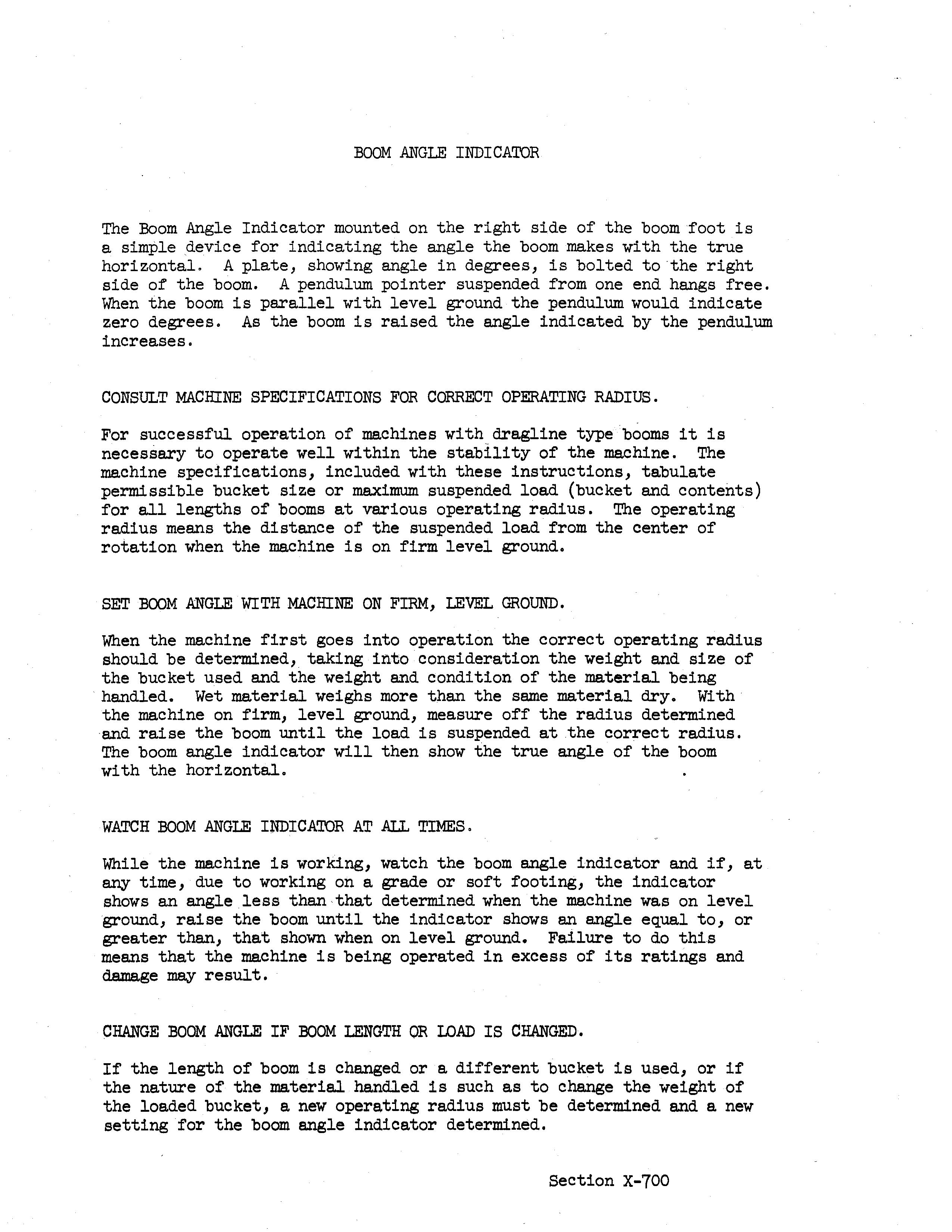
BOOM ANGLE INDICATOR
BOOM ANGLE INDICATOR
Boom mounted of for the angle makes horizontal, plate, showing angle in degrees, is bolted to the right of A pendulum one the boom the pendulum zero degrees. As the angle the pendulum
The Boom Angle Indicator mounted on the right side of the boom foot is a simple device for indicating the angle the boom makes with the true horizontal, A plate, showing angle in degrees, is bolted to the right side of the boom, A pendulum pointer suspended from one end hangs free, When the boom is parallel with level ground the pendulum would indicate zero degrees. As the boom is raised the angle indicated by the pendulum increases.
CONSULT MACHINE SPECIFICATIONS FOR CORRECT OPERATING RADIUS.
FOR
For successful operation of machines with dragline type booms it is necessary to operate well within the stability of the machine. The machine specifications, included with these instructions, tabulate permissible bucket size or maximum suspended load (bucket and contents) for all lengths of booms at various operating radius. The operating radius means the distance of the suspended load from the center of rotation when the machine is on firm level ground.
For successful machines necessary to operate within of with tabulate bucket size contents) lengths booms operating radius. operating radius means the distance of the suspended load from the center of when machine on firm level
SET BOOM ANGLE WITH MACHINE ON FIRM, LEVEL GROUND.
SET ANGLE WITH ON FIRM, LEVEL
When the machine first goes into operation the correct operating radius should be determined, taking into consideration the weight and size of the bucket used and the weight and condition of the material being handled. Wet material weighs more than the same material dry. Wi th the machine on firm, level ground, measure off the radius determined and raise the boom until the load is suspended at the correct radius. The boom angle indicator will then show the true angle of the boom with the horizontal.
When the machine first goes into operation the operating radius should be taking into consideration the weight and size of bucket and the weight material handled. Wet material material the machine firm, level ground, off the radius determined until the load is suspended the correct will then true angle of the boom horizontal.
WATCH BOOM ANGLE INDICATOR AT .ALL TIMES,
BOOM TIMES, machine the at any time, due to working on grade or soft footing, the indicator than· when the on ground, raise the boom until the indicator shows angle equal greater than, that shown that the machine is being operated in of its ratings and
While the machine is working, watch the boom angle indicator and if, at any time, due to working on a grade or soft footing, the indicator shows an angle less than· that determined when the machine was on level ground, raise the boom until the indicator shows an angle equal to, or greater than, that shown when on level ground. Failure to do this means that the machine is being operated in excess of its ratings and damage may result.
CHANGE
CHANGE BOOM OR
BOOM ANGLE IF BOOM LENGTH OR LOAD IS CHANGED.
If the length of boom is changed or a different bucket is used, or if the nature of the material handled is such as to change the weight of the loaded bucket, a new operating radius must be determined and a new setting for the boom angle indicator determined.
If the length of boom is changed a different bucket is used, if the material handled such as to change the a new must a new the angle indicator
Section X-700
Section X-700
MACHINE ':4. ''EO< "C'
/lOB JJe" 16"
/5013 .5 S-%'" 13"
/QO.B ..5 '-!{; .5 34" 13"
INSTRUCTIONS FOR ADJUSTMENT OF PROPEL BRAKE
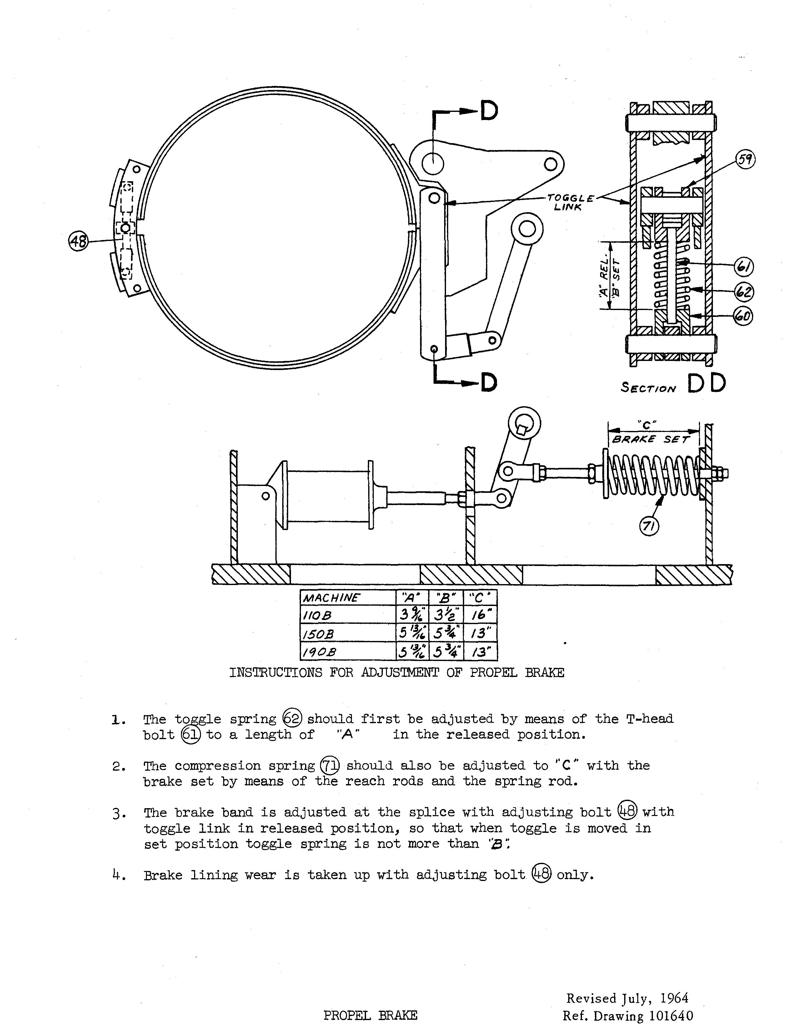
The t.2§.gle spring ® should first be adjusted by means of the T-head. bol t ® to a length of "A" in the released position.
The compression spring @ should also be adjusted to /' C" with the brake set by means of the reach rods and the spring rod.
The brake band is adjusted at the splice with adjusting bolt @ with toggle link in released position, so that when toggle is moved in set position toggle spring is not more than ':8 ';
Brake lining wear is taken up with adjusting bolt @ only.
Lower roller --;----....It\.
Lower roller---t----
Crawler frame
Crawler frame
frame Jack \o4---Front axle
Take-up tumbler--"t-
Take-up
Crawler Belts
Crawler Belts
Retainer bars
Crawler belt
bars
No definite rule can be given as to how tight or loose the tread belts should be as the correct adjustment depends on the type of ground over which the machine is to be moved. In general, the belts should be kept as loose as possible without losing proper tracking of the driving tumblers.
definite can be the correct adjustment depends the type of ground which the machine is to be moved. In general, the belts should be kept as loose as possible without proper tracking driving tumblers.
Adjustment
Crawler
Adjustment of Crawler Belts
Adjustment of the crawler belts is made at the take-up tumbler end of The single the cat frames. Chock in retainer, axle the tension on
Adjustment of the crawler belts is made at the take-up tumbler end of the mounting. The take-up tumblers are bushed on a single forged axle which slides in guides formed in the cat side frames. Chock bars, held in place by a retainer, hold the axle with the desired tension on the belts.
To adjust the crawler belts, first remove the chock bar retainer from each side bolted on the take-up axle. Then place the hydraulic jack furnished with the machine in position on one side between the truck frame and the take-up axle as shown on the drawing. Be sure jack handle points up. Pump the jack until the cat belt is just tight enough to insure proper tracking of the driving tumbler. Insert the necessary thickness of chock bars, back off the hydraulic jack and replace chock bar retainer. Repeat this procedure on the other side; be sure to insert the same thickness of chock bars.

To the crawler belts, first remove the chock bar retainer from side bolted the take-up place the hydraulic jack with the machine truck frame as shown on sure handle points Pump the jack until the cat belt is tight enough insure proper tracking of the driving tumbler. the bars, retainer. Repeat on the be sure to insert same thickness chock bars.
After the crawler belts have been properly adjusted, store the hydraulic jack where it will be readily available the next time it is needed.
have properly adjusted, hydraulic jack where it available needed. June, Ref. Drawing
• Thank you very much for reading the preview of the manual.
• You can download the complete manual from: www.heydownloads.com by clicking the link below
• Please note: If there is no response to CLICKING the link, please download this PDF first and then click on it.