CAT 39HR BLAST HOLE DRILL OPERATOR’S MANUAL 10661 – PDF DOWNLOAD

Page 1

10661 39HR BLASTHOLEDRILL 39HR BucyrusInternational,Inc. 1100MilwaukeeAve.•P.O.Box500•SouthMilwaukee,Wisconsin53172-0500USA 141248mc.cdrPg. SN:141248 SN:141249 BLASTHOLEDRILL ManualNo. 10661 OPERATOR’S MANUAL OPERATOR’S MANUAL 2 BI617151

• Thank you very much for reading the preview of the manual.

• You can download the complete manual from: www.heydownloads.com by clicking the link below

• Please note: If there is no response to CLICKING the link, please download this PDF first and then click on it.

CLICK HERE TO DOWNLOAD THE COMPLETE MANUAL
39HR Blast Hole Drill Manual No. 10661 Dec 2008 Bucyrus International, Inc. BI617151

DANGER:

THIS MANUAL PROVIDES INFORMATION AND DATA FOR THE MAINTENANCE AND OPERATION OF THIS MACHINE. ALL ELECTRICAL EQUIPMENT MUST BE SERVICED BY QUALIFIED INDIVIDUALS WHO HAVE BEEN PROPERLY TRAINED TO WORK WITH HIGH VOLTAGE SYSTEMS, VARIABLE FREQUENCY AC DRIVES, AND/ OR WARD LEONARD LOOP DC DRIVES. FAILURE TO COMPLY COULD RESULT IN PERSONAL INJURY OR DEATH.

DANGER:

DO NOT ATTEMPT MECHANICAL OR ELECTRICAL MAINTENANCE ON THIS MACHINE WITHOUT A FULL UNDERSTANDING OF EACH COMPONENT’S OPERATION AND FUNCTION. COMPONENTS UTILIZING ELECTRICAL POWER, AIR PRESSURE, HYDRAULIC PRESSURE AND COMPRESSION OR TENSION SPRINGS FOR OPERATION MUST BE DEACTIVATED AND ISOLATED PRIOR TO DISASSEMBLY.

The FEEDER CABLE must contain a provision for a ground connection, especially whenever 2,300 volts or greater are used. At the substation, the power line must terminate (see paragraph on ground circuits) to a suitable permanent ground. At the machine, the power line must securely terminate through a bolted connection to the machine frame. This provides a constant ground for the machine and its electrical equipment. Failure to provide this adequate ground endangers employees and equipment.

THE NEED FOR A POWER LINE GROUNDING CIRCUIT ADEQUATE FOR THE MACHINE CANNOT BE OVEREMPHASIZED. Without a good grounding system, high voltages exist between the machine and the ground. The portable trail cable and power lines supplying electric energy to the machine must have a ground wire, ample in capacity, running parallel to the main wires over the entire distance from the transformer to the machine. A suitable grounding system must be used at the transformer. Consult your local electrical supplier for details.

DANGER:

DUE TO THE INHERENT DANGERS IN THE OPERATION OF HIGH VOLTAGE ELECTRICAL EQUIPMENT, A SAFE GROUNDING SYSTEM IS REQUIRED THAT INCLUDES GROUND CONDUCTORS IN THE CABLE, A NEUTRAL GROUNDING RESISTOR, AND RELATED RELAYS AND SWITCHGEAR. A GROUND CONTINUITY CHECK SYSTEM IS ALSO RECOMMENDED.

39HR Blast Hole Drill Dec 2008 Manual No. 10661 Bucyrus International, Inc.
BI617151
39HR Blast Hole Drill Manual No. 10661 Dec 2008 Bucyrus International, Inc. BI617151
39HR Blast Hole Drill Bucyrus International, Inc. Dec 2008 1 Manual No. 10661 39HR Blast Hole Drill Operator’s Manual Manual No. 10660 sn: 141248 • Lot 16 sn: 141249 • Lot 17 Always refer to the safety information in this section of this manual before starting any maintenance procedure on this machine. Table of Contents GENERAL INFORMATION ............................................................................................................4 SAFETY ..................................................................................................................................5 SAFETY PRECAUTIONS ........................................................................................................6 FIRE PREVENTION 9 WARNING SIGNS AND DECALS ..........................................................................................10 Standard Warning Signs ...10 Stored Energy Warning Signs 11 Machine Overview ......................................................................................................................12 LOWER WORKS .......................................................................................................................13 MAIN FRAME ............................................................................................................................... 14 OPERATOR’S CAB....................................................................................................................15 OPERATOR’S SEAT..................................................................................................................16 POWER MODULE......................................................................................................................17 MAST ...........................................................................................................................................18 DRILL STRING COMPONENTS .................................................................................................19 MAST HOIST CYLINDERS ...................................................................................................20 MAST MACHINERY ...............................................................................................................21 HOSE DRUM CARRIER ASSEMBLY....................................................................................22 UPPER WINCH BEAM..........................................................................................................23 LOWER TENSIONING ARM ..................................................................................................23 BREAKOUT WRENCH...............................................................................................................24 TOOL WRENCH.........................................................................................................................25 PIPE RETENTION DEVICE..................................................................................................26 PIPE HANDLING ARM .................................................................................................................27 WATER TANKS..........................................................................................................................28 OPERATION NEAR ELECTRICAL LINES.............................................................................29 STANDARD HAND SIGNALS - CRANE OPERATIONS..............................................................30 OPERATIONAL INFORMATION AND THEORY ..........................................................................33 Typical Tri-Cone Roller Drill Bit Components ...............................................................................34 Carbide Drill Teeth Used For Various Formations .......................................................................35 Formation - Bit Selection Compatibility Chart .............................................................................37 BI617151
39HR Blast Hole Drill Bucyrus International, Inc. Manual No. 10661 2 Dec 2008 MACHINE SPECIFIC CONSIDERATIONS ..................................................................................38 OPERATOR CONTROLS ..........................................................................................................39 CONTROL CONSOLES AND PANELS......................................................................................39 Operator’s Cab ...........................................................................................................................40 OPERATOR’S DISPLAY............................................................................................................. 41 DISPLAY AREA & INDICATORS............................................................................................41 DISPLAY SCREENS.............................................................................................................42 Title Screen ...............................................................................................................................42 Main Menu .................................................................................................................................43 Leveling Screen .........................................................................................................................43 Active Alarm ...........44 New Alarm .................................................................................................................................44 Alarms Help Screen ......45 Setup Screen .............................................................................................................................45 PLC/Profibus Menu ....................................................................................................................46 Calibration and Limits .......46 Calibration Help.........................................................................................................................47 Operating Hours/Fault Counters .................................................................................................47 Field Tests Screen ........48 Status Screen ..........49 STATUS SCREEN GAUGES, DISPLAYS & INDICATORS........................................49 LEFT CONTROL CONSOLE................................................................................................55 CONTROLS ON THE LEFT CONTROL CONSOLE......................................................56 RIGHT CONTROL CONSOLE..............................................................................................60 CONTROLS ON THE RIGHT CONTROL CONSOLE....................................................61 AUXILIARY OPERATOR’S CONTROL CONSOLE...............................................................65 MACHINE OPERATION ...............................................................................................................66 DAILY INSPECTION PROCEDURES...................................................................................67 PRESTART LUBRICATION...................................................................................................70 MACHINERY CHECKS ............................................................................................................... 70 BREAK-IN OF NEW COMPONENTS...................................................................................70 OPERATING PROCEDURES....................................................................................................71 PROPELLING .......................................................................................................................71 Gradual Turns - 15° Increments..................................................................................................73 LEVELING .............................................................................................................................74 MAST RAISING/LOWERING .................................................................................................76 RAISING THE MAST ........................................................................................................76 LOWERING THE MAST..................................................................................................77 PULLDOWN ...79 CHECKING THE HOIST BRAKE....................................................................................79 PULLDOWN OPERATION..............................................................................................79 AUXILIARY WINCH ................................................................................................................80 PIPE LOADING AND UNLOADING ........................................................................................81 PREPARATION ...............................................................................................................81 LOADING PIPE ................................................................................................................81 UNLOADING PIPE .................................................................................................................82 BI617151
39HR Blast Hole Drill Bucyrus International, Inc. Dec 2008 3 Manual No. 10661 HANDLING ARM ..........................................................................................................................84 HANDLING ARM OPERATION ..............................................................................................85 TOOL HANDLING ........................................................................................................................85 TOOL WRENCH...................................................................................................................85 BREAKOUT WRENCH.........................................................................................................87 DRILL TOOL STRING ASSEMBLY..............................................................................................89 ADDING ADDITIONAL DRILL PIPE .......................................................................................95 MULTIPLE SECTIONED DRILL PIPE DISASSEMBLY ..........................................................97 TOOL HANDLING FOR ANGLE DRILLING PROCEDURES................................................98 DRILLING ....................................................................................................................................99 VERTICAL DRILLING ............................................................................................................99 STARTING THE HOLE (COLLARING)..........................................................................100 NORMAL DRILLING .......................................................................................................102 ENDING THE HOLE (SINGLE PASS DRILLING) ..........................................................104 ENDING THE HOLE (MULTIPLE PASS DRILLING) ......................................................104 DRILLING DIFFICULT FORMATIONS ...........................................................................105 UNCONSOLIDATED MATERIALS .................................................................................105 WET OR STICKY FORMATIONS.................................................................................107 ANGLE DRILLING ...............................................................................................................108 MOVING TO THE NEXT HOLE LOCATION..................................................................109 DRILL STABILITY CHART .........................................................................................................110 MACHINE SHUTDOWN ............................................................................................................111 NORMAL SHUTDOWN .......................................................................................................111 MACHINE STORAGE ................................................................................................................113 SHORT TERM STORAGE..................................................................................................113 LONG TERM STORAGE....................................................................................................114 ATTENDED LONG TERM STORAGE................................................................................114 UNATTENDED LONG TERM STORAGE...........................................................................115 TYPICAL OPERATING SPECIFICATIONS ................................................................................116 TYPICAL MACHINE SPECIFICATIONS .....................................................................................117 GENERAL ESTIMATED COMPONENT WEIGHTS..................................................................119 OPERATOR’S DISPLAY INSTRUCTIONS................................................................................125 BI617151

GENERAL INFORMATION

This manual is designed to assist the owner in the operation and preventive maintenance of this machine. By following easy to understand step-by-step procedures the operators and maintenance personnel can perform all tasks in a safe manner. It is important to remember that when a systematic and thorough maintenance/service procedure is used for this machine, a minimum of unplanned downtime and more reliable operation will result.

RIGHT and LEFT refer to machine locations as viewed by the operator with the mast as the rear of the machine.

THIS MANUAL IS NOT THE PARTS BOOK and cannot be used as reference material to order parts. A separate, detailed parts book has been supplied. Please state the correct machine SERIAL NUMBER when corresponding or contacting the factory service or parts departments. Records on each machine are filed by serial number and when given this number, the machine’s specific design and original equipment is accessed quickly by the Bucyrus International parts representative.

Periodic additions or revisions may be made to this manual. These can be ordered and will be mailed direct to you from the factory. Should you require additional information or factory service assistance contact your regional service representative or:

Bucyrus International, Inc.

1100 Milwaukee Avenue

P.O. Box 500

South Milwaukee, Wisconsin 53172-0500, USA

Telephone (414)-768-4000Fax: (414) 768-4210

It is Bucyrus International’s policy to improve its products whenever possible and practical to do so. The company reserves the right to make changes or add improvements to its machines at any time. This will be without incurred obligation to install such changes on machines sold previously.

Due to this ongoing program of product research and development, some procedures, specifications and parts may be altered in a constant effort to improve our machines.

39HR Blast Hole Drill Bucyrus International, Inc. Manual No. 10661 4 Dec 2008
Section 1 Introduction
BI617151

The safety alert symbols displayed here and throughout this manual are used to call attention to instructions concerning personal safety. Carefully read and follow these instructions and observe all SAFETY, DANGER and CAUTION graphics mounted on various areas of the machine.

Be certain anyone servicing this machine is aware of these SAFETY SYMBOLS and their definitions. If there are questions or concerns on safely performing any of the enclosed maintenance and operational procedures, contact your regional Bucyrus service representative, or the factory.

The following defines distinctions between safety instructions. In all these definitions, the safety alert signal is used.

NOTE: This signal word denotes an item of required information pertaining to the equipment. A loss of time or assets, or injury may result if the appropriate action is not taken.

CAUTION:This signal word serves as a reminder of safety practices, or directs attention to specific safety practices which could prevent possible injury if precautions are not adhered to.

DANGER:This signal word denotes an imminently dangerous hazard that will result in death, serious bodily injury, or serious damage to equipment if not acknowledged and appropriate action taken.

DANGER:This signal word denotes an imminently dangerous electrical hazard which will result in death, serious bodily injury, or serious damage to equipment if not acknowledged and appropriate action taken.

Operating, maintaining or servicing this machine is dangerous unless performed properly. Each person must be alert, and must have the necessary skills, knowledge, proper tools and equipment for the task at hand. It is critical that all the methods used are safe and correct. Factory service representatives and specialists are available to provide additional information or technical assistance. The operator must be alert, physically fit and free from the influence of alcohol, drugs, or any medications that might impair his eyesight, hearing or reactions.

Safety must always be paramount!

Consult your supervisor when safety is in doubt.

39HR Blast Hole Drill Bucyrus International, Inc. Dec 2008 5 Manual No. 10661
SAFETY
BI617151

SAFETY PRECAUTIONS

General Precautions:

•The employment of qualified maintenance personnel, through a scheduled maintenance program, is the best way to minimize machine downtime and maximize productivity of equipment.

•Keep hands, feet and clothing away from rotating parts.

•Wear a hard hat, safety shoes and protective lenses at all times.

•Replace any and all safety and warning placards if they are defaced or removed from the machine.

•Think before you act. Carelessness is one luxury the service person cannot afford.

•Excessive or repeated skin contact with sealants or solvents may cause skin irritation. In case of skin contact refer to the Material Safety Data Sheet (MSDS) for that material and the suggested method of cleanup.

•Inspect safety catches (keepers) on all hoist hooks. Do not take a chance, the load could slip off of the hook if they are not functioning properly.

•If a heavy item begins to fall, let it fall, don’t try to catch it.

•Keep your work area organized and clean. Wipe up oil or spills of any kind immediately. Keep tools and parts off of the ground. Eliminate the possibility of a fall, slipping or tripping.

•Floors, walkways and stairways must be clean and dry. After fluid draining operations be sure all spillage is cleaned up.

•Electrical cords and wet metal floors make a dangerous combination.

•Regularly inspect for any loose bolts or locking devices and properly secure them.

•Use extreme caution while working near any electrical lines or equipment whether it be high or low voltage. Never attempt electrical repairs unless you are qualified.

•Check limit switches for proper operation.

•After servicing, be sure all tools, parts or servicing equipment are removed from the machine and secured in an appropriate storage area.

•Mechanical Brakes are designed for use as static holding brakes only. Use as a motion (dynamic) brake in emergency situations only.

•Use proper interior and exterior lighting.

•Install and maintain proper grounding and ground fault protection systems.

•Allow electrical inspection and maintenance to be performed only by a qualified electrician.

•Use extreme caution when working around drilled holes.

39HR Blast Hole Drill Bucyrus International, Inc. Manual No. 10661 6 Dec 2008
BI617151

Maintenance Precautions:

•Do not wear rings, wristwatches or loose fitting clothing when working on machinery. They could get caught on moving parts causing serious injury.

•Always wear a safety belt or harness when the danger of falling exists.

•Always have a second person to monitor the lifeline when working in confined spaces.

•Never utilize the machine air or hydraulic systems for support when working on the machine. Deactivate or isolate the entire system prior to performing maintenance.

•Equipment should be parked on level ground at all times during machine servicing and periods of idleness.

•Cranes and hoists must be of sufficient capacity to lift the heavier components (gearcases, pipe arms, etc.) Always work within the limitations of the equipment being utilized.

•Be sure heavy items are properly rigged and supported from cranes or hoists before removing supporting members from the machine.

•Utilize guide lines or ropes to minimize the swing of suspended heavy components.

•Have sufficient service personnel available when removing or installing large heavy items to maintain control at all times.

•Always use safety stands in conjunction with hydraulic jacks or hoists. Do not rely on the jack or hoist to carry the load, they could fail.

•When disassembling a machine, be sure to use safety stands and adequate cribbing to prevent tipping or rollover of components.

•When using an oxy/acetylene torch, always wear welding goggles and gloves. Keep a charged fire extinguisher within reach. Be sure the acetylene and oxygen tanks are separated by a metal shield and are chained to the cart.

•Use pullers to remove bearings, bushings, gears, cylinder sleeves, etc. when applicable. Use hammers, punches and drifts only when absolutely necessary. Always be sure to wear safety glasses.

•Use extreme caution when using compressed air to dry parts. Use approved air blowguns, do not exceed 30 PSI (207 kPa), wear safety glasses or goggles and use proper shielding to protect everyone in the work area.

•Be sure to promptly reinstall safety devices, guards or shields after adjusting and/or servicing the machine.

•Protective eye goggles should be worn at all times when working on the air conditioning system. Work on the air conditioning system only in a well ventilated area.

39HR Blast Hole Drill Bucyrus International, Inc. Dec 2008 7 Manual No. 10661
BI617151

•Wipe away excess lubricants around bearings and gears. Never lubricate parts in motion.

•Always wear approved rubber gloves and use insulated hooks or tongs when handling trail cable.

Operating Precautions:

•Wear hearing protection when exposed to the following noise levels in excess of the period indicated:

8 hours at 90 dBa

4 hours at 95 dBa

2 hours at 100 dBa

1 hour at 105 dBa

30 minutes at 110 dBa

15 minutes at 115 dBa

•When in doubt about the noise level, wear approved hearing protection.

•Do not attempt to get on or off the machine while it is in operation. Notify the operator prior to any attempt to board/exit the machine.

•Do not move or operate the machine without first knowing the location and purpose of all personnel, test or support equipment, on or near the machine.

•Do not allow personnel on board the machine while it is in operation.

•Do not operate the machine with personnel on the deck or within 5 feet of the machine.

•Use audible signals to warn of machine movements. A signal horn button is provided for this purpose.

•Do not propel until the travel route has been cleared of obstructions.

•Do not propel the machine on a slope greater than that specified in Section 2 ~ OPERATION in this manual.

•Prevent trail cable from being dragged on the ground for long distances or at high speeds.

•Limit the amount of cable being pulled by the machine. Pulling too much cable will damage both the cable and the machine.

39HR Blast Hole Drill Bucyrus International, Inc. Manual No. 10661 8 Dec 2008
BI617151

FIRE PREVENTION

•Always have a “charged” fire extinguisher on hand and know how to use it. Inspect and service the extinguisher as indicated on its instruction plate.

•DO NOT smoke while handling flammables or when near batteries.

•Inspect all lines, tubes and hoses carefully. Tighten all connections to the recommended torque. For general maintenance recommendations refer to Section 4 - PREVENTIVE MAINTENANCE in this manual.

•Repair or replace loose or damaged lines, tubes and hoses as soon as possible.

•Make certain all clamps, guards and shields are replaced correctly so as to prevent vibration and the chafing of parts during operation.

•DO NOT carry flammable fluids such as gasoline or solvents on board the machine.

•DO NOT over-bend or strike pressurized lines or hoses. DO NOT install bent or damaged lines, tubes, or hoses. Replace them immediately.

•DO NOT start the machine or move any of the controls if a warning tag or lockout is attached to the controls or the start panel.

•Keep all cleaning rags properly stored. DO NOT discard them into a pile on board the machine.

•Keep all structural frame compartments, walkways and work areas clean and free of lubricant residue.

•NEVER weld, burn, or perform service on the machine without someone to assist.

•If a motor or other component is running hot, shutdown the machine until it has cooled and the cause is determined and repaired.

39HR Blast Hole Drill Bucyrus International, Inc. Dec 2008 9 Manual No. 10661
BI617151

WARNING SIGNS AND DECALS

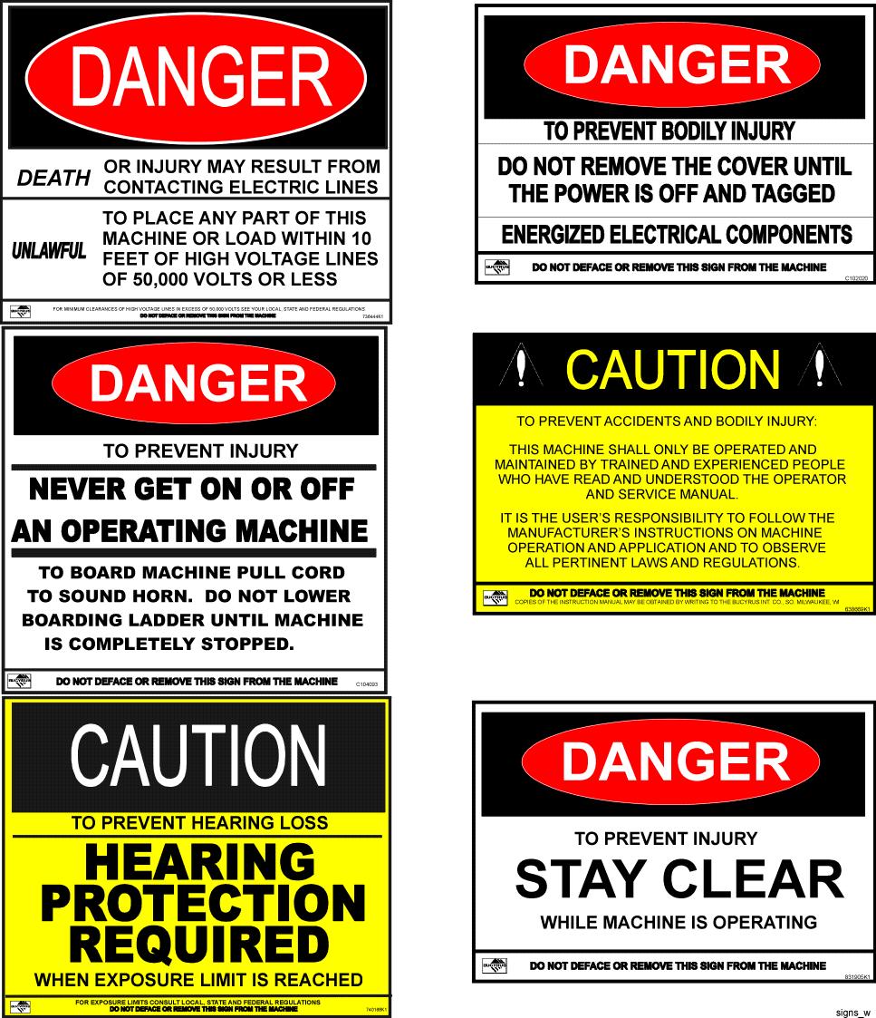
The placards depicted below are mounted on the machine as delivered from Bucyrus International, Inc. These hazard-warning placards convey information to operators, maintenance personnel, or anyone who will be on or near the machine. The information is designed to help prevent situations that may result in injury to personnel or damage to the machine.

Standard Warning Signs

39HR Blast Hole Drill Bucyrus International, Inc. Manual No. 10661 10 Dec 2008
BI617151
39HR Blast Hole Drill Bucyrus International, Inc. Dec 2008 11 Manual No. 10661
Energy Warning Signs BI617151
Stored

Mast

Winch Beam, Upper

Winch

Rope

Drum Assembly, Hose

Mast Machinery

Shock Coupling

Drill Pipe

Pipe Retention Device

Mast Hoist Cylinder

Leveling Jack, Rear

Mast Pivot

Tensioning Arm, Lower Mast Winch Breakout Wrench

Tool Wrench

Jack Pad

Separator

(Far Side)

Operator’s Cab

(Far Side)

Power Module

Air Intake, Compressor Tank, Hydraulic Front of Machine

Electric Motor (Far Side)

Cooler, Compressor

Motor Control Center

Mast Rest

Pipe Handling Arm

Cooler, PDT

Cooler, Hydraulic

Main Frame Assembly

Leveling Jack, Front

141248_nm

Jack Pad

Boarding Stairs

Drill Hole

Crawler Drive Sprocket Crawler Assembly

CL Water Tank (2)

Machine Overview

39HR Blast Hole Drill Bucyrus International, Inc.
No.
12 Dec 2008
Manual
10661
BI617151
39HR Blast Hole Drill Bucyrus International, Inc. Dec 2008 13 Manual No. 10661 LOWER WORKS BI617151
39HR Blast Hole Drill Bucyrus International, Inc. Manual No. 10661 14 Dec 2008 MAIN FRAME BI617151

• Thank you very much for reading the preview of the manual.

• You can download the complete manual from: www.heydownloads.com by clicking the link below

• Please note: If there is no response to CLICKING the link, please download this PDF first and then click on it.

CLICK HERE TO DOWNLOAD THE COMPLETE MANUAL

Turn static files into dynamic content formats.

Create a flipbook
Issuu converts static files into: digital portfolios, online yearbooks, online catalogs, digital photo albums and more. Sign up and create your flipbook.