Z-Force-S Brake adjustment NOTE: When performing a brake adjustment, inspect the brake components for signs of wear or damage. 1.
Block the front wheels.
2.
Lift and safely support the rear of the mower.
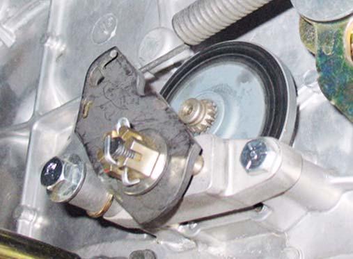
Castellated nut
NOTE: Make sure the parking brake is released. 3.
Remove the cotter pin locking the castle nut on the brake caliper. See Figure 3.3.
4.
Back the castle nut off a few turns using a 9/16” wrench. NOTE: Even if the brakes are set to the correct clearance, inserting a feeler gauge between the rotor and the brake puck can be very difficult. Loosen the castle nut first, then insert the feeler gauge and tighten the nut to set the proper clearances
Cotter pin Figure 3.3
5.
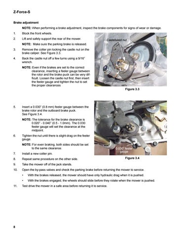
Insert a 0.030” (0.8 mm) feeler gauge between the brake rotor and the outboard brake puck. See Figure 3.4. NOTE: The tolerance for the brake clearance is 0.020” - 0.040” (0.5 - 1.0mm). The 0.030 feeler gauge will set the clearance at the midpoint.
6.
Tighten the nut until there is slight drag on the feeler gauge. NOTE: For even braking, both sides should be set to the same clearance.
0.030” feeler gauge
7.
Install a new cotter pin.
8.
Repeat same procedure on the other side.
9.
Take the mower off of the jack stands.
10.
Open the by-pass valves and check the parking brake before returning the mower to service.
11.
8
Figure 3.4
•
With the brakes released, the mower should have only hydraulic drag when it is pushed.
•
With the brakes engaged, the wheels should slide before they rotate when the mower is pushed.
Test drive the mower in a safe area before returning it to service.