Workshop manual
AForeword
BSafety
CPreventive maintenance
0Complete machine
1Engine
2Transmission
3Driveline/axle
4Brakes
5Steering
6Suspension
7Load handling
8Control system
9Frame, body, cab and accessories
10Common hydraulics
11Common electrics
12Common pneumatics
DError codes
ESchematics
FTechnical data
GTerminology
• Thank you very much for reading the preview of the manual.
• You can download the complete manual from: www.heydownloads.com by clicking the link below
• Please note: If there is no response to CLICKING the link, please download this PDF first and then click on it.

VDRF01.01GB
Workshop manual DRF 400–450
About the Workshop Manual General
Thank you for choosing Kalmar Industries as your machine supplier. We hope that we'll meet your expectations.
Workshop manual contents
The workshop manual contains information for corrective maintenance (replacement of components) and complements the maintenance manual. Accompanying the workshop manual is supplier documentation for engine, transmission and drive axle. Where practicable, please refer from the workshop manual to the maintenance manual and supplier documentation to avoid duplicated information. The workshop manual is divided into the following sections.
AForewordGeneral information about the workshop manual's purpose, contents and reading instructions as well as survey for feedback of views and any inaccuracies.
BSafetyKeep in mind for your safety.
CPreventive maintenanceReference to maintenance manual: Preventive maintenance.
0Complete machine
Technical description, comprehensive function descriptions and a description of the function of components included in the machine, divided into function groups.
The components used for each function are described under each subfunction. Consequently, common components are described in several places, but in general under the first function to use the component.
Together with the general description is a detailed description of what is unique about the specific subfunction. The next subfunction to use the same component only has a description what is unique for the new function. Work instructions for corrective maintenance (replacement of components).
DError codesReference to maintenance manual: Error code information and instructions for reading error code information.
ESchematicsReference to maintenance manual: Wiring and hydraulic diagrams
FTechnical dataTechnical data, conversion tables, information for conversion of units.
GTerminology and indexGeneral terminology and abbreviations, explanation of terms and abbreviations that can appear in the sections, index for headings in the sections.
References between different information types
The maintenance manual and workshop manual are mainly divided into function groups, see Workshop manual contents page 3. Certain parts are broken out as separate parts to increase usability, e.g., “Technical data”.
The basic rule of searching for information is to use function groups to find different types of information regarding the function or component in question. As a complement to this, there are references according to the below.
•From Function description to Component description, to enable fast finding of more information about the different components that create a function.
•From Function description to Hydraulic diagram, to enable fast finding of the right hydraulic diagram for the function in question.
•From Component description or Function description to Diagnostic test, to enable fast finding of the right diagnostic menu that can be used to check the component (only applies to electrical components).
•From Diagnostic test to Wiring diagrams. to enable fast finding of the right circuit diagram for further troubleshooting.
•From Diagnostic test to Component description or Function description. To enable fast finding of more information about the component's appearance and position when troubleshooting.
•From Error codes to Diagnostic test, to enable fast finding of the right diagnostic menu to troubleshoot component or function in question.
•From Error codes to Function description or Component description, to enable fast finding of more information about components or function.
Workshop manual DRF 400–450 VDRF01.01GB
Function group breakdown
Breakdown into function groups is common for all machines from Kalmar Industries, down to two-digit heading level (e.g., 4.3 Powerassisted brake system). Machine-unique adaptations of function groups are done at the third and fourth group levels (e.g., 4.3.9 Wheel brake resp. 4.3.9.1 Disc pack).
This results in certain headings (function groups) being omitted in the documentation for certain machines since the machine lacks that particular function. This means that there may be gaps in the function groups' numbering (e.g., the three-digit heading level 4.8.7 Oil cooler may be included for certain machines, but may be missing for other machines).
References between manual types (of the type "see Workshop manual DFR 400–450") are used since the different manual types have different purposes and thus different information content.
References between sections within the same manual are indicated using section and group number, e.g., "see section 4 Brakes, group 4.3.9 Wheel brake". A reference within the same section is indicated with page number, e.g., "see Sensor fuel level, description page 24".
Conditions
The instructions are based on the use of generally available standard tools. All lifting devices, for example, slings, straps, ratchet blocks, etc., must meet governing national standards and regulations for lifting devices.
Kalmar Industries will not accept any responsibility for modifications performed without permission from Kalmar Industries or if other lifting devices, tools or work methods are used other than those described in this manual.
Storage
NOTE
The Maintenance Manual should be accessible to the service personnel.
About the machine version
The information in this publication corresponds to the machine's design and appearance at the time of delivery from Kalmar Industries. Due to customizations, there may be variations and/or deviations. Kalmar Industries reserves the right to modify specifications and equipment without prior notice. All information and data in this manual are valid at the time of publication.
VDRF01.01GB
Copyright
Kalmar Industries AB
Duplication of the content in this manual, in whole or in part, is strictly prohibited without written permission from Kalmar Industries AB.
Duplication by any means such as copying, printing, etc., is prohibited.
Workshop manual DRF 400–450
Read the operator’s manual/maintenance manual
Reading instructions
Warning information
Warnings inform on potential dangers which can, if the warnings are not heeded, result in personal injury or product damage.
DANGER
Situation that may result in serious personal injury, possible death, if the instruction is not followed.
WARNING
Situation that may result in serious personal injury if the instruction is not followed.
CAUTION
Situation that may result in damage to the product if the instruction is not followed.
Important information
Important information marked with NOTE facilitates the work process, operation/handling or increases understanding of the information.
NOTE
Information that is important without being safety related.
Read the operator's manual/maintenance manual
The symbol to the left is used in certain cases on the machine and refers to important information in the operator’s/maintenance manual.
Optional equipment
Indicates optional equipment
The symbol to the left is used in the manual to indicate that a function or component is optional equipment. Detailed information on how the machine is equipped is presented by the machine card enclosed with the spare parts catalogue.
Workshop manual DRF 400–450 VDRF01.01GB
VDRF01.01GB
Function descriptions
Function descriptions are schematic overviews that describe how a function works as well as which components and signals work together.
Function descriptions describe the function in a logical flow from input signal to desired output signal. Most functions require that preset conditions are fulfilled for the function to be activated. In these cases, the conditions are listed above the illustration.
Function descriptions use symbols to illustrate components such as valves, sensors, etc.
Workshop manual DRF 400–450
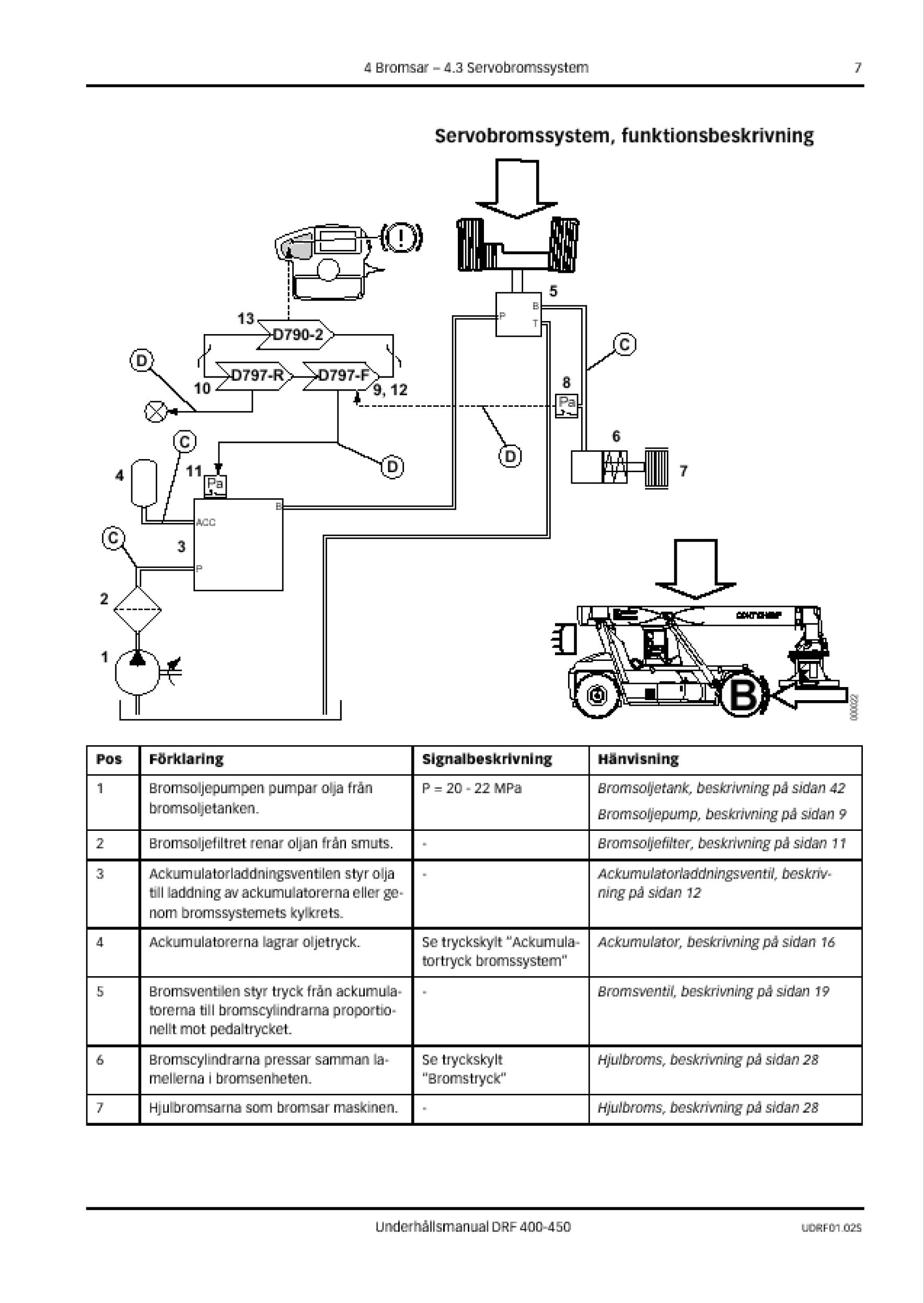
1.Hydraulic force (solid double line)
2.Flag pressure check connection (Check point), indicates that there is pressure check connection for checking pressure signal
3.Flag diagnostic test, indicates that signal can be checked with diagnostic test, see group “8.4 Diagnostic test”
4.Illustration of function, (applied brake)
5.Reference to description of component
6.Signal description, reference value for signal out from component
7.Description of component's function
8.Position number, reference to position in illustration
9.Position number in illustration, reference to row in table
10.Electric power (solid single line)
VDRF01.01GB
Symbol explanation function descriptions
The following symbols are used in function descriptions, the symbols are based on standard symbols used in wiring and hydraulic diagrams.
1.Electric control signal
2.Electric force
3.Hydraulic control signal
4.Hydraulic force
5.Hydraulic motor
6.Hydraulic oil pump with variable displacement
7.Hydraulic oil pump with fixed displacement
8.Electric motor
9.Accumulator
10.Disc brake
11.Filter
12.Radiator
13.Bulb
14.Control system, two control units with CAN-bus
15.Restriction
16.Adjustable restriction
17.Inductive position sensor
18.Electrically controlled servo valve
19.Thermal by-pass valve
20.Temperature-controlled switch
21.Temperature sensor
22.Pressure sensor
23.Pressure-controlled switch
24.Hydraulic cylinder
25.Double-acting hydraulic cylinder
26.Spring brake cylinder
27. Valve block
28.Shuttle valve
29.Non-return valve
Workshop manual DRF 400–450
About the documentation
Documentation sections
The documentation to the machine comprises the following sections:
Operator's manual
The Operator's manual is supplied with the machine in the cab.
Documentation kit
Maintenance manual and spare parts catalogue with machine card are supplied with the machine as a separate documentation kit.
Supplementary documentation
There are Supplementary documentation that can be ordered for the machine in the form of a Workshop manual. The Workshop manual includes supplier documentation for engine, transmission and drive axle.
Ordering of documentation
Extra copies and supplementary documentation is ordered from Kalmar Industries.
Kalmar Industries AB
SE-341 81 Ljungby, Sweden.
NOTE
If possible, always indicate publication number when ordering.
Workshop manual DRF 400–450 VDRF01.01GB
• Thank you very much for reading the preview of the manual.
• You can download the complete manual from: www.heydownloads.com by clicking the link below
• Please note: If there is no response to CLICKING the link, please download this PDF first and then click on it.