8 Control and monitoring system
Error codes machine
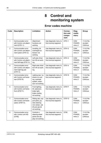
Attachment functions not working.
Levelling, tilt, overheight extension not working.
Left side of bottom lift not working.
Right side ofbottom lift not working.
Lighting rear, hydraulic oil cooling, overload system, extension not working.
Use diagnostic menu to find incorrect segment.
Use diagnostic menu to find incorrect segment.
Use diagnostic menu to find incorrect segment.
Use diagnostic menu to find incorrect segment.
Use diagnostic menu to find incorrect segment.
D797-R
CAN/ POWER, menu 2
11.6.2 Redundant CAN-bus
6 Communication error with Control unit frame front (D797-F).
7 Communication error with Control unit frame option (D797-O).
Front lighting, lift, extension, brake light, brake cooling not working.
Sliding cab, support jacks, joystick steering mini-wheel, cab lift and cab tilt not working.
Use diagnostic menu to find incorrect segment.
D797-F
CAN/ POWER, menu 2
11.6.2 Redundant CAN-bus
8 Communication error with Control unit KID (D795).
Controls in steering wheel panel and display not working.
Use diagnostic menu to find incorrect segment.
D797-O CAN/ POWER, menu 2
11.6.2 Redundant CAN-bus
Use diagnostic menu to find incorrect segment.
D795 CAN/ POWER, menu 2
11.6.2 Redundant CAN-bus
50 D Error codes – 8 Control and monitoring system Workshop manual DRF 400–450 VDRF03.01GB
Code Description Limitation Action Connection and component Diagnostic menu Group
D791-1 CAN/ POWER, menu 2 11.6.2 Redundant CAN-bus
D791-2 CAN/ POWER, menu 2 11.6.2 Re-
dundant CAN-bus
D791-3 CAN/ POWER, menu
11.6.2
2
Redundant CAN-bus
CAN/ POWER, menu 2
D791-4
11.6.2 Redundant CAN-bus
• Thank you very much for reading the preview of the manual.
• You can download the complete manual from: www.heydownloads.com by clicking the link below
• Please note: If there is no response to CLICKING the link, please download this PDF first and then click on it.

CLICK HERE TO DOWNLOAD THE COMPLETE MANUAL
CLICK HERE TO DOWNLOAD THE COMPLETE MANUAL
D Error codes – 8 Control and monitoring system 51 Workshop manual DRF 400–450 VDRF03.01GB Code Description Limitation Action Connection and component Diagnostic menu Group 9 Communication error with Control unit cab option (D790-3). Mini-wheel or joystick steering not working Use diagnostic menu to find incorrect segment. D790-3 CAN/ POWER, menu 2 11.6.2 Redundant CAN-bus 11 Cable defect CAN-net segment 1. No limitation. Use diagnostic menu to find incorrect segment. Varies depending on machine configuration. CAN/ POWER, menu 1 and 21 11.6.2 Redundant CAN-bus 12 Cable defect CAN-net segment 2. No limitation. Use diagnostic menu to find incorrect segment. Varies depending on machine configuration. CAN/ POWER, menu 1 and 21 11.6.2 Redundant CAN-bus 13 Cable defect CAN-net segment 3. No limitation. Use diagnostic menu to find incorrect segment. Varies depending on machine configuration. CAN/ POWER, menu 1 and 21 11.6.2 Redundant CAN-bus 14 Cable defect CAN-net segment 4. No limitation. Use diagnostic menu to find incorrect segment. Varies depending on machine configuration. CAN/ POWER, menu 1 and 21 11.6.2 Redundant CAN-bus 15 Cable defect CAN-net segment 5. No limitation. Use diagnostic menu to find incorrect segment. Varies depending on machine configuration. CAN/ POWER, menu 1 and 21 11.6.2 Redundant CAN-bus 16 Cable defect CAN-net segment 6. No limitation. Use diagnostic menu to find incorrect segment. Varies depending on machine configuration. CAN/ POWER, menu 1 and 21 11.6.2 Redundant CAN-bus 17 Cable defect CAN-net segment 7. No limitation. Use diagnostic menu to find incorrect segment. Varies depending on machine configuration. CAN/ POWER, menu 1 and 21 11.6.2 Redundant CAN-bus 18 Cable defect CAN-net segment 8. No limitation. Use diagnostic menu to find incorrect segment. Varies depending on machine configuration. CAN/ POWER, menu 1 and 21 11.6.2 Redundant CAN-bus
20 Accelerator pedal (B690) not calibrated.
Poor sensitivity in accelerator pedal.
Calibrate the accelerator pedal, see tab 8 Control system, group 8.5.2.3 Calibrate DRIVE-TRAIN
D790-1/ K6:11 –B690
TION: DRIVETRAIN, menu 1 and 2
21 Communication error with Control unit transmission (D793).
Gear selection not working.
Use diagnostic menu to check communication.
D790-1/ K13:1 –D793/M2
D790-1/ K13:2 –D793/L2
Engine does not react to commands from cab.
CAN/
POWER, menu 3
drivetrain
No controls working in cab. Contact Kalmar Industries AB.
24 Electric power feed to cab fan less than 18 V. Cab fan not working. Check fuse
25 Interference during soft- ware download. Buffer for error codes from Control unit engine (D794), active error code when download- ing.
Turn the ignition off and on.
D794 ENGINE,
8 11.5.3.10 Control unit engine 26 27 28 29 30
52 D Error codes – 8 Control and monitoring system
–
Workshop manual DRF 400
450 VDRF03.01GB
Connection and component Diagnostic menu Group
Code Description Limitation Action
CALIBRA-
1. Engine
CAN/
Check cable harness between Control unit cab (D790-1) and Control unit transmission (D793). 11.6.3 CAN-bus
POWER, menu 3
drivetrain
22 Communication error with Control unit engine (D794).
Use diagnostic menu to check communication. Check cable harness between Control unit cab (D790-1)and Control unit engine (D794). 11.6.3 CAN-bus
Volvo: D790-1/ K13:1, K13:2 –D794/2, 1 Cummins: D790-1/ K13:1, K13:2 –D794/46, 37
23 The setup file cannot be read in Control unit cab (D790-1).
D790-1 - 11.5.3.1 Control unit cab
D790-1/ K2:8 – 585/3:2 - 9.4.3 Cab fan
F58-5/3.
Error code is stored in Control unit engine (D794).
Repeat software download.
menu
Code Description Limitation Action
31 Incorrect electric power feed toControl unit cab (D790-1). Voltagelower than 18 V or higher than 32 V.
32 Incorrect 5 V reference voltage to analogue controls in the cab. Voltage lower than 4.9 V or higher than 5.1 V.
Control in cab not working. Check fuse F58-5/1. Check cable harness between the control unit and the component with diagnostic menu.
Check the control unit.
D790-1/ K1:2, K1:3, K1:4 –F58-5/1:1, 1:2
POWER, menu 6
11.5.1.3 Ignition voltage (15)
Analogue controls in the cab not working (mini-wheel/joystick, control lever and controls for air conditioning).
Check cable harness between the control unit and the component with diagnostic menu.
Check the component.
D790-1/ K4:5, K 5:11, K5:13, K7:2, K 9:7, K10:3
POWER, menu 6
11.5.3.1 Control unit cab
33 No feedback signal for control breaker voltage from Relay control breaker voltage (K30091).
34 Incorrect signal from Switch parking brake (S107), indicates released and applied at same time or not at all.
35 Interference during software download. Buffer for error codes from Control unit transmission (D793), active error code when downloading.
41 The transistor has been triggered due to shortcircuiting in the circuit to Wiper motor, rear (M650-2).
Control breaker cannot be disengaged. All hydraulic functions are blocked.
Parking brake cannot be released.
Check fuse F58-3/8. Check cable harness between the control unit and the component with diagnostic menu.
Check cable harness between the control unit and the component with diagnostic menu.
Check the switch.
D790-1/ K11:13 –K3009-1/ 87
D791-1/ K8:5 –S107/7
D791-1/ K8:13 –S107/1
CAN/ POWER, menu 5
11.5.1.4 Control breaker voltage (15E)
HYD, menu 5 4.5 Parking brake
Error code is stored in Control unit transmission (D793).
Turn the ignition off and on.
D793
TRANSM,
Windshield wiper rear not working.
Check cable harness betweenthecontrolunit andthecomponentwith diagnostic menu.
Check the motor.
D790-1/ K2:4 –M650-2/53
CAB, menu 3 9.5.7 Wiper motor rear
D Error codes – 8 Control and monitoring system 53 Workshop manual DRF 400–450 VDRF03.01GB
Connection and component Diagnostic menu Group
CAN/
CAN/
Repeat software download. 36 37 38 39 40
menu 13 11.5.3.9 Control unit transmission
Code Description Limitation Action
42 The transistor hasbeen triggered due to shortcircuitingin the circuit to Rotating beacon (H428).
43 The transistor has been triggered due to shortcircuiting in the circuit to Work light cab left (E404-1L).
44 The transistor has been triggered due to shortcircuiting in the circuit to Work light cab right (E404-1R).
45 The transistor has been triggered due to shortcircuiting in the circuit to Wiper motor, front (M650-1).
46 The transistor has been triggered due to shortcircuiting in the circuit to Fan motor (M657-1).
47 The transistor has been triggered due to shortcircuiting in the circuit to Actuator recirculation (M612).
48 The transistor has been triggered due to shortcircuiting in the circuit to Water valve (Y673).
49 The transistor has been triggered due to shortcircuiting in the circuit to Water valve (Y673).
Rotating beacon not working.
Check cable harness between the control unit and the component with diagnostic menu.
Check the component.
D790-1/ K2:5 –H428
LIGHTS, menu 9 9.6.8 Rotating beacon
Work light cab left not working.
Check the light. Check cable harness between the control unit and the component with diagnostic menu.
D790-1/ K2:6 –E404-1L
LIGHTS, menu 1 9.6.9 Work lights cab
Work light cab right not working.
Check the light. Check cable harness between the control unit and the component with diagnostic menu.
D790-1/ K2:7 –E404-1R
LIGHTS, menu 1 9.6.9 Work lights cab
Windshield wiper front not working.
Check cable harness betweenthecontrolunit andthecomponentwith diagnostic menu.
Check the motor.
Cab fan not working. Check cable harness betweenthecontrolunit andthecomponentwith diagnostic menu.
Check the motor.
D790-1/ K2:1 –M650-1/53
CAB, menu 2 9.5.1 Wiper front
D790-1/ K2:2 –M657-1/2
CLIMATE, menu 6
9.4.3 Cab fan
The recirculation damper for ventilation is not working.
Check cable harness betweenthecontrolunit andthecomponentwith diagnostic menu.
Check the motor.
Heat in cab cannot be adjusted. Check cable harness betweenthecontrolunit andthecomponentwith diagnostic menu.
Check the motor.
Heat in cab cannot be adjusted. Check cable harness betweenthecontrolunit andthecomponentwith diagnostic menu.
Check the motor.
D790-1/ K2:3 –M612/3
CLIMATE, menu 6
9.4.2 Fresh air and recirculation damper
D790-1/ K4:1 –Y673/5
CLIMATE, menu 7
9.4.5 Water valve
D790-1/ K4:2 –Y673/6
CLIMATE, menu 7
9.4.5 Water valve
54 D Error codes – 8 Control and monitoring system Workshop manual DRF 400–450 VDRF03.01GB
Connection and component Diagnostic menu
Group
Code Description
50 The transistor has been triggered due to shortcircuiting in the circuit to Damper motor (Y672)
51 The transistor has been triggered due to shortcircuiting in the circuit to Damper motor (Y672).
53 The transistor has been triggered due to shortcircuiting in the circuit to Washer motor roof and rear (M651-2).
54 The transistor has been triggered due to shortcircuiting or open circuit in the circuit to Switch flashing hazard lights (S109).
55 The transistor has been triggered due to shortcircuiting in the circuit to background lighting in switches and instruments.
56 The transistor has been triggered due to shortcircuiting or open circuit in the circuit to LED-indication for tilt lock in control lever (S815).
57 The transistor has been triggered due to shortcircuiting or open circuit in the circuit to LED-indication for levelling lock in control lever (S815).
Air distribution in cab cannot be adjusted.
Check cable harness betweenthecontrolunit andthecomponentwith diagnostic menu.
Check the motor.
Air distribution in cab cannot be adjusted.
Check cable harness betweenthecontrolunit andthecomponentwith diagnostic menu.
Check the motor.
Windshield washer rear and roof not working.
Check cable harness betweenthecontrolunit andthecomponentwith diagnostic menu.
Check the motor.
Flashing hazard lights not working.
Check cable harness between the control unit and the component with diagnostic menu.
Check the switch.
D790-1/ K5:5 –S109/
Air distributor
Reduced or no background lighting in switches and instruments
Indication for tilt lock in control lever is not illuminated.
Check bulbs for background lighting, change if needed.
Check cable harness to background lighting.
Check cable harness between the control unit and the component with diagnostic menu.
Check the switch.
D7901/ K6:1, K 8:15, K9:2, K 10:5, all inputs type A Digital in
D790-1/ K7:8 –S815/5
Washer motor and reservoir
LIGHTS, menu 7 9.6.7 Flashing hazard lights
LIGHTS, menu 13 9.1 Controls and instruments
- 7.1.1 Control lever
Indication for levelling lock in control lever is not illuminated.
Check cable harness between the control unit and the component with diagnostic menu.
Check the switch.
D790-1/ K7:9 –S815/7
- 7.1.1 Control lever
D Error codes – 8 Control and monitoring system 55 Workshop manual DRF 400–450 VDRF03.01GB
Connection and component Diagnostic menu Group
Limitation Action
D790-1/
CLI-
9.4.14
K4:3 –Y672/5
MATE, menu 8
Air distributor
D790-1/
CLIMATE,
9.4.14
K4:4 –Y672/6
menu 8
D790-1/ K5:4
M651-2 CAB,
9.5.4
–
menu 1
60 The transistor has been triggered due to shortcircuiting or open circuit in the circuit to Relay seat heater (K383).
61 The transistor has been triggered due to shortcircuiting or open circuit in the circuit to Relay extra work light boom (K304).
62 The transistor has been triggered due to shortcircuiting or open circuit in the circuit to simulated D+ feed to hour meter (P708) and Relay compressor air-suspended seat (K358).
63 The transistor has been triggered due to shortcircuiting or open circuit in the circuit to Relay ignition voltage (K315-1).
64 The transistor has been triggered due to shortcircuiting or open circuit in the circuit to Relay control breaker voltage (K3009-1).
65 The transistor has been triggered due to shortcircuiting or open circuit in the circuit to Relay control breaker voltage (K3009-2).
66 The transistor has been triggered due to shortcircuiting in the circuit to Washer motor windshield (M651-1).
Seat heater not working. Check cable harness between the control unit and the component with diagnostic menu.
Check the component.
D790-1/ K10:7 –K383/86
CAB, menu 8 9.3.3 Heating coils
Extra work light boom not working.
Check cable harness between the control unit and the component with diagnostic menu.
Check the component.
D790-1/ K10:8 –K304/86
LIGHTS, menu 3 9.6.10 Work light boom
Hour meter and air-suspended seat not working.
Check cable harness between the control unit and the component with diagnostic menu.
Check the component.
D790-1/ K10:9 –P708, K358/86
CAN/ POWER, menu 7
9.3.5 Air suspension
No ignition voltage to the machine's Control units.
No control breaker voltage to the machine's Control units.
Check cable harness between the control unit and the component with diagnostic menu.
Check the component.
Check cable harness between the control unit and the component with diagnostic menu.
Check the component.
D790-1/ K10:10 –K315-1/86
CAN/ POWER, menu 4
11.5.1.3 Ignition voltage (15)
No control breaker voltage to the machine's Control units.
Check cable harness between the control unit and the component with diagnostic menu.
Check the component.
D790-1/ K10:11 –K3009-1/ 86
CAN/ POWER, menu 5
11.5.1.4 Control breaker voltage
Windshield washer not working.
Check cable harness between the control unit and the component with diagnostic menu.
Check the component.
D790-1/ K10:11 –K3009-1/ 86
D790-1/ K10:13 –M651-1
CAN/ POWER, menu 5
11.5.1.4 Control breaker voltage
CAB, menu 1 9.5.4 Washer motor and reservoir
56 D Error codes – 8 Control and monitoring system Workshop manual DRF 400–450 VDRF03.01GB
Connection and component Diagnostic menu Group
Code Description Limitation Action
67 The transistor has been triggered due to shortcircuiting or open circuit in the circuit to Wiper motor, roof (M650-3).
68 The transistor has been triggered due to shortcircuiting or open circuit in the circuit to Circulation pump pause heater (M667).
69 The transistor has been triggered due to shortcircuiting or open circuit in the circuit to Relay ignition voltage drivetrain (K315-2).
71 The transistor has been triggered due to shortcircuiting in the circuit to Interior lighting cab (E434-1).
74 The transistor has been triggered due to shortcircuiting in the circuit to Horn (H850) or Relay compressed air horn (K3016)
75 Relay ignition voltage (K315-1) has jammed in position on.
Wiper roof not working. Check cable harness betweenthecontrolunit andthecomponentwith diagnostic menu.
Check the motor.
D790-1/ K10:14 –M650-3/53
CAB, menu 4 9.5.6 Wiper motor roof
Pause heater not working.
Check cable harness betweenthecontrolunit andthecomponentwith diagnostic menu.
Check the motor.
D790-1/ K10:15 –M667
- 9.4 Heating, ventilation and air conditioning
No voltage feed to engine and transmission.
Check cable harness between the control unit and the component with diagnostic menu.
Check the component.
D790-1/ K10:16
K315-2/86
CAN/ POWER, menu 4
11.5.1.3 Ignition voltage (15)
Interior lighting in cab not working.
Check the light. Check cable harness between the control unit and the component with diagnostic menu.
D790-1/ K11:6 –E434-1
LIGHTS, menu 12 9.6.12 Interior lighting cab
Horn / compressed air horn not working.
Check cable harness between the control unit and the component with diagnostic menu.
Check the component.
D790-1/ K11:11 –H850/1, K3016/86
5
80 No signal from Pressure switch air conditioning (S246), despite the AC compressor being activated.
Control unit cab (D790-1) is still supplied with voltage and thus active.
Air conditioning not working.
Check cable harness between the control unit and the component with diagnostic menu.
Check the component.
Check drive belt for air conditioning compressor.
Check that compressor for air conditioning is activated.
Check cable harness between the control unit and the component with diagnostic menu.
D797-R/ K1:37
S246
menu 4
Ignition voltage
MATE, menu 3
9.4.10 Pressure monitor
D Error codes – 8 Control and monitoring system 57 Workshop manual DRF 400–450 VDRF03.01GB
Connection and component Diagnostic menu Group
Code Description Limitation Action
–
CAB,
menu
9.7.1 Horn
CAN/
-
POWER,
11.5.1.3
CLI-
–
81 Incorrect signal fromDamper motor (Y672). Signal voltage lower than0.2Vorhigherthan 4.8 V.
85 Incorrect signal fromaccelerator pedal (R690). Signal voltage lower than0.2Vorhigherthan 4.8 V.
87 Incorrect signal from Control lever (S815-P1) for lift and lower. Signal voltage lower than 0.2 V or higher than 4.8 V.
88 Incorrect signal from Control lever (S815-P2) for extension. Signal voltage lower than 0.2 V or higher than 4.8 V.
89 Incorrect signal from Control lever (S815-P3) for rotation. Signal voltage lower than 0.2 V or higher than 4.8 V.
90 Incorrect signal from Control lever (S815-P4) for tilt. Signal voltage lower than 0.2 V or higher than 4.8 V.
92 Incorrect signal from Joystick (R825-1) or Mini-wheel (R825-1). Signal voltage lower than0.2Vorhigherthan 4.8 V.
93 Incorrect signal from Mini-wheel (R825-2). Signal voltage lower than0.2Vorhigherthan 4.8 V.
Air distribution cannot be changed.
Check cable harness betweenthecontrolunit andthecomponentwith diagnostic menu.
Check the motor.
Engine rpm limited to idle. Check cable harness between the control unit and the component with diagnostic menu.
Check the component.
Lift and lower not working. Check cable harness between the control unit and the component with diagnostic menu.
Check the switch.
Extension not working. Check cable harness between the control unit and the component with diagnostic menu.
Check the switch.
Rotation not working. Check cable harness between the control unit and the component with diagnostic menu.
Check the switch.
Controllable tilt not working. Check cable harness between the control unit and the component with diagnostic menu.
Check the switch.
D790-1/ K4:7 –Y672/9
CLIMATE, menu 4
9.4.6 Fresh air and recirculation damper
D790-1/ K6:11 –R690/2
ENGINE, menu 1 1 Engine
D790-1/ K7:3 –S815-P1/8
BOOM, menu 1
7.1.1 Control lever
D790-1/ K7:4 –S815-P2/4
BOOM, menu 1 7.1.1 Control lever
D790-1/ K7:5 –S815-P3/ 11
D790-1/ K7:6 –S815-P4/1
ATTACH, menu 1 7.1.1 Control lever
Joystick steering or mini-wheel not working.
Check cable harness between the control unit and the component with diagnostic menu.
Check the switch.
ATTACH, menu 1 7.1.1 Control lever
Joystick steering or mini-wheel not working.
Check cable harness between the control unit and the component with diagnostic menu.
Check the switch.
D790-1/ K9:8 –R825-1/P2
STEERING, menu 1
5.1.2 Miniwheel 5.1.3 Joystick
D790-1/ K9:9 –R825-2/H2
STEERING, menu 1
5.1.2 Miniwheel
58 D Error codes – 8 Control and monitoring system Workshop manual DRF 400–450 VDRF03.01GB
Connection and component
nostic menu
Code Description Limitation Action
Diag-
Group
Code Description Limitation Action
94 Incorrect signal from Water valve cab heat (Y673). Signal voltage lower than 0.2 V or higher than 4.8 V.
96 Incorrect signal from Sensor cab temperature (B775-1). The sensor indicates temperature below -43 C or above 105 C.
97 Incorrect signal from Sensor outdoor temperature (B774). Temperature signal above 105 C.
98 Incorrect signal from Sensor temperature outlet fan (B775-2). The sensor indicates temperature below -43 C or above 105 C.
99 Incorrect signal from Sensor temperature refrigerant (B775-3). The sensor indicates temperature below -43 C or above 105 C.
101 Redundant voltagefeed left to Control unit frame front (D797-F) does not arrive.
Cab heat cannot be adjusted. Check cable harness betweenthecontrolunit andthecomponentwith diagnostic menu.
Check the motor.
Air conditioning not working.
Check cable harness between the control unit and the component with diagnostic menu.
Check the sensor.
Air conditioning not working. Check cable harness between the control unit and the component with diagnostic menu.
Air conditioning not working. Check cable harness between the control unit and the component with diagnostic menu.
D790-1/ K4:9 –B774/2
MATE, menu
Check the sensor. CLI-
MATE, menu 2
Sensor cab temperature
9.4.18
102 Redundant voltage feed right to Control unit frame front (D797-F) does not arrive.
Air conditioning not working. Check cable harness between the control unit and the component with diagnostic menu.
Check the sensor.
- Check cable harness between the control unit and the component with diagnostic menu.
Check the control unit.
- Check cable harness between the control unit and the component with diagnostic menu.
Check the control unit.
D790-1/ K4:11 –B775-3/2
CLIMATE, menu 2
D797-F/ K2:7 CAN/ POWER, menu 8
9.4.16 Sensor temperature outlet fan
9.4.12 Sensor temperature refrigerant
11.5.1.2 Redundant voltage feed of Control units
D797-F/ K2:8 CAN/ POWER, menu 8
11.5.1.2 Redundant voltage feed of Control units
D Error codes – 8 Control and monitoring system 59 Workshop manual DRF 400–450 VDRF03.01GB
Connection and component Diagnostic menu Group
D790-1/
Y673/9 CLIMATE,
9.4.5
K10:4 –
menu 4
Water valve
CLIMATE,
9.4.17
D790-1/ K4:8 –B775-1/2
menu 1
Check the sensor. CLI-
2
Sensor outdoor temperature
D790-1/ K4:10 –B775-2/2
103 Incorrect electric power feed to Control unit
frame front (D797-F). Voltage lower than 18 V or higher than 32 V.
104 Incorrect control breakervoltagetoControlunit
frame front (D797-F).
No electric power feed to components.
Check fuse F58-2/1, change if needed.
Check cable harness between the control unit and the component with diagnostic menu.
D797-F/ K2:1, K2:9, K2:10 –F58-2/1:1, 1:2
CAN/ POWER, menu 8
11.5.1.3 Ignition voltage (15)
105 Incorrect 5 V reference voltage to pressure sensor. Voltage lower than 4.9 V or higher than 5.1 V.
106 The transistor has been triggered due to shortcircuiting in the circuit to Cooling fan, brake oil (M674).
107 The transistor has been triggered due to shortcircuiting or open circuit in the circuit to High beam light left (E402L).
108 The transistor has been triggered due to shortcircuiting or open circuit in the circuit to High beam light right (E402R).
110 The transistor has been triggered due to shortcircuiting or open circuit in the circuit toLow beam light (E400L/ E400R).
Functions supplied with control breaker voltage have no feed. All hydraulic functions are blocked.
Regeneration lift, weight indicator and overload system not working.
Cooling fan brake oil not working.
Check fuse F58-3/2, change if needed.
Check cable harness between the control unit and the component with diagnostic menu.
Check cable harness between the control unit and the component with diagnostic menu.
Check the sensor.
Check cable harness betweenthecontrolunit andthecomponentwith diagnostic menu.
Check the motor.
D797-F/ K2:11
F58-3/2:1
POWER, menu 8
11.5.1.4 Control breaker voltage
D797-F/ K1:8 –B768-R1/1, B768-R2/1, B768-L1/1, B768-L2/1
D797-F/ K1:14 –M674/1
CAN/ POWER, menu 9
8.2.1.7 Sensor hydraulic pressure lift cylinder
HYD, menu 2 4.8.8 Cooling fan
Left high beam not working.
Check the light.
Check the bulb holder. Check cable harness between the control unit and the component with diagnostic menu.
D797-F/ K1:1 –E402L/1
LIGHTS, menu 6 9.6.1 Headlights
Right high beam not working.
Check the light. Check the bulb holder.
Check cable harness between the control unit and the component with diagnostic menu.
D797-F/ K1:15 –E402R/1
LIGHTS, menu 6 9.6.1 Headlights
Low beams not working.
Check the light.
Check the bulb holder. Check cable harness between the control unit and the component with diagnostic menu.
D797-F/ K1:42 –E400L/1, E400R/1
LIGHTS, menu 6 9.6.1 Headlights
60 D Error codes – 8 Control and monitoring system Workshop manual DRF 400–450 VDRF03.01GB
Description Limitation Action Connection and component Diagnostic menu Group
Code
–
CAN/
111 The transistor has been triggered due to shortcircuiting in the circuit to Solenoid valve boom up (Y6005).
112 The transistor has been triggered due to shortcircuiting in the circuit to Solenoid valve boom down (Y6004).
113 The transistor has been triggered due to shortcircuiting in the circuit to Solenoid valve boom out (Y6006).
114 The transistor has been triggered due to shortcircuiting in the circuit to Solenoid valve boom in (Y6007).
115 The transistor has been triggered due to shortcircuiting or open circuit in the circuit to Solenoid valve blocking lift left (Y6002).
116 The transistor has been triggered due to shortcircuiting or open circuit in the circuit to Solenoid valve blocking lift right (Y6001).
117 The transistor has been triggered due to shortcircuiting or open circuit in the circuit to Solenoid valve regeneration lift right (Y6051).
Lift not working. Check cable harness between the control unit and the component with diagnostic menu.
Check the solenoid valve.
Lower not working. Check cable harness between the control unit and the component with diagnostic menu. Check the solenoid valve.
Extension out not working. Check cable harness between the control unit and the component with diagnostic menu. Check the solenoid valve.
Extension in not working. Check cable harness between the control unit and the component with diagnostic menu.
Check the solenoid valve.
Lift and lower not working. Check cable harness between the control unit and the component with diagnostic menu.
Check the solenoid valve.
Lift and lower not working. Check cable harness between the control unit and the component with diagnostic menu.
Check the solenoid valve.
Regenerating lift not working. Check cable harness between the control unit and the component with diagnostic menu.
Check the solenoid valve.
D797-F/ K1:2 –Y6005/1
BOOM, menu 4 7.2.5 Control valve lift, lower and extension
D797-F/ K1:3 –Y6004/1
BOOM, menu 5 7.2.5 Control valve lift, lower and extension
D797-F/ K1:4 –Y6006/1
BOOM, menu 7 7.3.5 Control valve lift, lower and extension
D797-F/ K1:5 –Y6007/1
BOOM, menu 6 7.3.5 Control valve lift, lower and extension
D797-F/ K1:30 –Y6002/1
BOOM, menu 2 7.2.7 Valve block lift cylinder
D797-F/ K1:31 –Y6001/1
BOOM, menu 2 7.2.7 Valve block lift cylinder
D797-F/ K1:32
Y6051/1
BOOM, menu 3 7.2.7 Valve block lift cylinder
D Error codes – 8 Control and monitoring system 61 Workshop manual DRF 400–450 VDRF03.01GB
Limitation
Connection and component Diagnostic menu Group
Code Description
Action
–
118 The transistor has been triggered due to shortcircuiting or open circuit in the circuit to Solenoid valve regeneration lift left (Y6052).
119 The transistor has been triggered due to shortcircuiting or open circuit in the circuit to Solenoid valve parking brake (Y642).
120 The transistor has been triggered due to shortcircuiting or open circuit in the circuit to Light bulb direction indicator left front (H422).
121 The transistor has been triggered due to shortcircuiting or open circuit in the circuit to Light bulb direction indicator right front (H423).
122 The transistor has been triggered due to shortcircuiting or open circuit in the circuit to Light bulb running light left front H416-1).
123 The transistor has been triggered due to shortcircuiting or open circuit in the circuit to Light bulb running light right front (H417-1).
Regenerating lift not working.
Check cable harness between the control unit and the component with diagnostic menu.
Check the solenoid valve.
D797-F/ K1:33 –Y6052/1
BOOM, menu 3 7.2.7 Valve block lift cylinder
Parking brake cannot be released.
Check cable harness between the control unit and the component with diagnostic menu.
Check the solenoid valve.
D797-F/ K1:7 –Y642/1
HYD, menu 5 4.5.3 Solenoid valve parking brake
Direction indicator left front not working.
Check the light. Check the bulb holder. Check cable harness between the control unit and the component with diagnostic menu.
D797-F/ K1:9 –H422/1
LIGHTS, menu 8 9.6.6 Direction indicators
Direction indicator right front not working.
Check the light. Check the bulb holder. Check cable harness between the control unit and the component with diagnostic menu.
D797-F/ K1:10 –H423/1
LIGHTS, menu 8 9.6.6 Direction indicators
Running light left front not working.
Check the light. Check the bulb holder. Check cable harness between the control unit and the component with diagnostic menu.
D797-F/ K1:25 –H416-1/1
LIGHTS, menu 5 9.6.2 Running lights
Running light right front not working.
Check the light. Check the bulb holder. Check cable harness between the control unit and the component with diagnostic menu.
D797-F/ K1:29 –H417-1/1
LIGHTS, menu 5 9.6.2 Running lights
62 D Error codes – 8 Control and monitoring system Workshop manual DRF 400–450 VDRF03.01GB
Connection and component Diagnostic menu
Code Description Limitation Action
Group
• Thank you very much for reading the preview of the manual.
• You can download the complete manual from: www.heydownloads.com by clicking the link below
• Please note: If there is no response to CLICKING the link, please download this PDF first and then click on it.
CLICK HERE TO DOWNLOAD THE COMPLETE MANUAL
CLICK HERE TO DOWNLOAD THE COMPLETE MANUAL