ÖËÒÙØÛ×ÒÎ×ÝØ
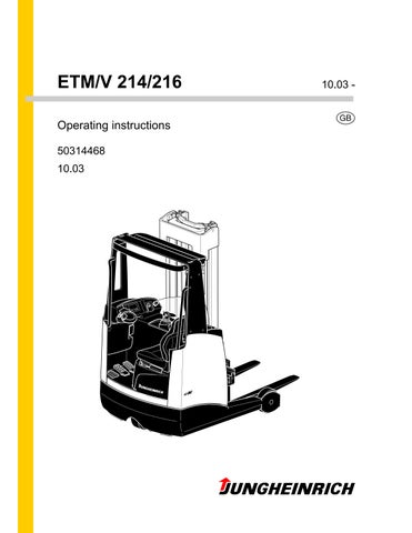
50314468 ETM/V 214/216 G 10.0310.03
Operating instructions
• Thank you very much for reading the preview of the manual.
• You can download the complete manual from: www.heydownloads.com by clicking the link below
• Please note: If there is no response to CLICKING the link, please download this PDF first and then click on it.

CLICK HERE TO DOWNLOAD THE COMPLETE MANUAL
CLICK HERE TO DOWNLOAD THE COMPLETE MANUAL
Important Instructions for Transporting and Assembling Reach Truck Masts Transport
Depending on the height of the mast and local conditions, the truck can be transported in three different ways: assembled (for low heights). partially assembled and leaning against the overhead guard (for medium heights), lifting hydraulic line disconnected. smantled (for large heights), all hydraulic lines between the basic truck and the mast separated.
Safety Instructions for Assembly and Commissioning
F On site assembly of the truck, commissioning and driver instruction may only be carried out by personnel trained and authorised by the manufacturer.
The hydraulic lines may only be connected to the basic truck / mast interface and the truck commissioned once the mast has been properly assembled.
Foreword
The present ORIGINAL OPERATING INSTRUCTIONS are designed to provide sufficient instruction for the safe operation of the industrial truck. The information is provided clearly and concisely. The chapters are arranged by letter. Each chapter starts with page 1. The page identification consists of a chapter letter and a page number.
For example: Page B 2 is the second page in chapter B.
The operating instructions detail different truck models. When operating and servicing the truck, make sure that the instructions apply to your truck model.
Safety instructions and important explanations are indicated by the following graphics:
F Used before safety instructions which must be observed to avoid danger to personnel.
MUsed before notices which must be observed to avoid material damage.
Z Used before notices and explanations.
t Used to indicate standard equipment.
o Used to indicate optional equipment.
Our trucks are subject to ongoing development. Jungheinrich reserves the right to alter the design, equipment and technical features of the truck. No guarantee of particular features of the truck should therefore be assumed from the present operating instructions.
Copyright
Copyright of these operating instructions remains with JUNGHEINRICH AG
Jungheinrich Aktiengesellschaft
Am Stadtrand 35
D-22047 Hamburg - Germany
Telephone: +49 (0) 40/6948-0
www.jungheinrich.com
ARegulatory Use of Machine
ZThe document „Guidelines for the Regulatory and Correct Use of Materials Handling Equipment“ (VDMA) is part of the delivery of this vehicle (VDMA). It forms part of the Operator Manual and its contents should be carefully observed. National regulations shall apply in their entirety.
The vehicle described in this instruction is a materials handling vehicle suitable for lifting and transporting loads. It must be employed, operated and maintained in accordance with the information contained in this manual. Any other use is not in keeping with this directive and can lead to damage to persons, machine or property. Above all overloading the machine due to excessively heavy loads or incorrectly positioned loads must be avoided. The maximum permissible load to be lifted is displayed on a data plate attached to the vehicle or on the load diagram. The vehicle must not be operated in areas exposed to the risk of fire or explosion, nor in a very dusty environment.
Duties of the Operator: In keeping with the sense of this manual the operator is any natural or legal person who operates the vehicle or for whom it is operated by another person. In special cases (e.g. leasing, hire) the operator is the person who in accordance with the existing contractual agreement between the owner and the user of the vehicle undertakes to carry out such operating duties. The operator must ensure that the vehicle is only used in accordance with the regulations and danger to life and limb of the user or a third party is avoided. Furthermore, regulations concerning accident prevention and special safety rules as well as guidelines for driving, maintenance and commissioning shall be observed. The operator must ensure that all users of the vehicle have read and understood this instruction.
MNon compliance with this instruction will render our warranty invalid. This also applies if sub-standard work has been carried out on the vehicle by the client and /or a third person without the consent of the manufacturer’s service department.
Fitting Attachments: Fitting or installing additional equipment which affects the operation of the vehicle or enhances these functions may only be undertaken with the written permission of the manufacturer. Where necessary permission shall be obtained from the local authority. Local authority approval does not take precedence over manufacturer’s approval.
A 1
BTruck Description 1Application
The ETM/V 214/216 is a three wheel electric side seated, clear view reach truck. It is designed for use on level floors to lift and transport goods. Open bottom pallets or palets with transverse boards can be lifted inside or outside the area of the load wheels, and trolleys can be lifted. Loads can be stacked or unstacked and transported over longer distances. The capacity may be obtained from the data plate.
B 1
Type Capacity Load Centre of Gravity ETM/V 214 1,400 kg 600 mm ETM/V 216 1,600 kg 600 mm
B 2 2Description of Assemblies
Item. Description Item. Description 1 t Clear View Lift Mast 10 t Accelerator 2 t Overhead Guard 11 t Battery trolley unlocking 3 t Free Lift Cylinder (not with ZT-Lifting Frame) 12 t Driver’s display 4 t Multi-Pilot o On board computer 5 t Load Wheels 13 t Two stage switch key with spare key (service). 6 t Outriggers o CANCODE 7 t Drive Wheel 14 t Emergency Stop Switch 8 t Dead man pedal 15 o Safety Belt 9 t Brake Pedal t Series Equipment o Auxiliary Equipment ïë ï î í ì ë ê é è ç ïð ïï ïî ïí ïì
and their Function
2.1Truck
Safety Instructions: An enclosed vehicle design with rounded edges facilitates safe handling of the ETM/V 214/216. The driver is protected by the driver’s cab (2). The drive wheel (7) and the load wheels (5) are protected by a solid anti-crash mechanism.
By activating the emergency switch all electrical power can be cut off in dangerous situations. The driver’s display unit (12) shows the following conditions:
–Lift limit reached (o)
–Slow travel
–Service interval expired (service mode active)
–Overtemperature
–Battery latching unlocked
–Parking brake applied
–Forks horizontal (o)
–Sideshifter in central position (o)
–Dead man pedal (safety switch) not activated
–System warning / system fault
Line break safety devices in the lift cylinders limit the lowering speed of the load in the event of a hydraulic system failure.
Display Instruments: Driver display (12) with large surface display using TFT technology (t) or on board computer with LCD display (o), each with integrated residual time display, battery charge status, lift and drive profile settings and steering angle mode display.
Traction Drive: The complete drive unit is enclosed in the vehicle chassis. A 6.9 kW fixed threephase motor operates the drive wheel (7) via a bevel spur gearbox. The electronic traction curr ent control system ensures the smooth rotation of the drive motor and as a result smooth driving, powerful acceleration and electrically controlled braking with energy recovery. The degree of energy recovery can be adjusted via the driver’s display unit.
B 3
Brake Equipment: The electric braking unit consists of three independent braking systems. Operating the brake pedal introduces regenerative braking. Where required the load wheel brakes are activated via the vehicle’s brake control system. The safety brake is electrically operated and works mechanically through a compression spring applied to a magnet brake mounted on the drive unit. This brake is used for emergency braking. A warning light appears when the brake is applied. Faults in the steering and braking systems (emergency stop trip) are shown on the driver’s display or the on board computer.
Emergency Stop Safety Concept: The emergency stop is controlled by the brake control system.
The steering control system transmits a system status signal which is monitored by the brake control. If the signal fails to appear or a fault is identified the brakes will be applied immediately until the machine comes to rest. Control displays on the driver’s display unit indicate an emergency stop. Each time the vehicle is switched on the system goes through a self diagnosis programme which only releases the parking brake (emergency stop) if a functionality check proves to be positive.
Steering: Electrical steering is operated through a spur gear. Access to the service mode on the driver’s display unit or the on board computer will afford a choice of three operating modes:
–180° (o)
–360° (continuous) (o)
–Switch between 180 - 360° via key (t)
The adjustable steering wheel serves as a steering transmitter.
Drivers Cab: The driver’s cab is designed ergonomically with ample foot room. To achieve the correct sitting position the driver’s seat and the steering head can be adjusted by the driver. Accelerator and brake pedals are arranged as in a normal lorry.
B 4
B 5 Item. Description Item. Description 1 t Clear View Lift Mast 10 t Accelerator 2 t Overhead Guard 11 t Battery trolley unlocking 3 t Free Lift Cylinder (not with ZT-Lifting Frame) 12 t Driver’s display 4 t Multi-Pilot o On board computer 5 t Load wheels 13 t Two stage switch key with spare key (service). 6 t Outriggers o CANCODE 7 t Drive wheel 14 t Emergency Stop Switch 8 t Dead man pedal 15 o Safety Belt 9 t Brake Pedal t Series Equipment o Auxiliary Equipment ïë ï î í ì ë ê é è ç ïð ïï ïî ïí ïì
Operating and Display Elements: Operating and display elements can be clearly identified in the driver’s cab.
The Multi-Pilot (4) enables single handed operation of functions governing direction of travel, lifting / lowering, mast forward / back, mast tilt, sideshift left or right in sideshift mode (auxiliary hydraulic system HF5) (o)) and horn.
On the driver’s display panel (12) the battery discharge indicator and hourmeter are grouped together. The discharge indicator is designed as a monitor which cuts out lifting if the battery is low in order to avoid excessive discharge.
Hydraulic Equipment: Pump unit with an AC motor and a noiseless precision high pressure pump. The equipment is controlled by the Multi-Pilot (4).
Electrical Equipment: 48 volt system in the form of a twin cable system. Series electronic drive, lift and steering control. The electronic drive control system governs the travel rate with infinite speed control and permits regenerative braking when changing direction. Drive and lift parameters can be set via the driver’s display unit (12). Warning displays, operating errors and service functions can also be shown at the driver’s display unit.
(For possible battery types, see Chapter D.)
2.2Placing the Load
Mast holder: The mast holder is mounted on suppert rollers. A simple telescopic pushing cylinder moves the holder backwards and forwards. The running rails for the mast holder are bolted on to the outriggers (6. )
Lifting Frame: The trucks are equipped with telescopic free lift units situated in the mast holder and which can be tilted. Adjustable side rollers and slide pieces take up the pressure exerted on the fork carriage if the load is positioned on one side. The fork arms are fitted to the fork carriage and are adjustable. With the twin lift Triplex mast (DZ) the first lift of the load carriage (free lift) is produced by a short, externally fitted lift cylinder (3) without changing the construction height. With a telescopic mast (ZT) the free lift is limited to 80 mm due to the design.
Attachments: Hydraulic and mechanical attachments are possible.
B 6
• Thank you very much for reading the preview of the manual.
• You can download the complete manual from: www.heydownloads.com by clicking the link below
• Please note: If there is no response to CLICKING the link, please download this PDF first and then click on it.
CLICK HERE TO DOWNLOAD THE COMPLETE MANUAL
CLICK HERE TO DOWNLOAD THE COMPLETE MANUAL