Media-ID: EM02922

Doc. -No: West Elk 03_81_00
Date: December 2018
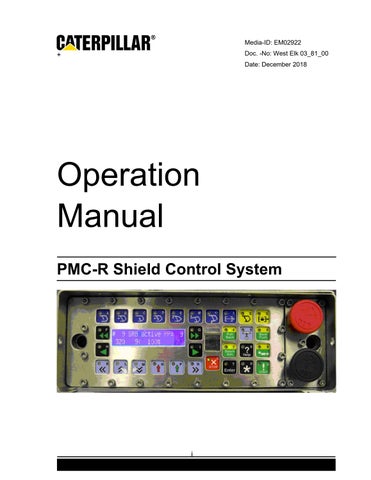
Operation Manual
PMC-R Shield Control System

+
i
• Thank you very much for reading the preview of the manual.
• You can download the complete manual from: www.heydownloads.com by clicking the link below
• Please note: If there is no response to CLICKING the link, please download this PDF first and then click on it.

CLICK HERE TO DOWNLOAD THE COMPLETE MANUAL
CLICK HERE TO DOWNLOAD THE COMPLETE MANUAL
ii
Table of Contents Description 1 Display 2 Display Categories 2 Default Display 2 Active Display 2 Master Display 3 Slave Display 3 Input Display 3 Keys 4 General Key Concepts 4 Audible Feedback 4 Timeout 4 Stuck Key Error 4 Multiple Key Error 4 Keyboard Modes 4 Idle Mode 4 Master Mode 5 Group Function Mode 5 Data Entry Mode 5 Help Mode 5 Specific Key Information 5 Hot keys 5 Single Select Keys 6 Man-In-Place Function Keys 7 In-Shield Automatic Keys 8 Group Select Keys 9 Group Function Keys 9 Number keys 10 Menu Navigation Keys 10 Other Keys 11 Menu Control 12 Navigation 12 iii
Freeze Display Feature 13 Go-Back Feature 13 Parameter Changing 14 Local / Global Parameters 15 Parameter Locking 15 Safety Features 16 Local Lockout Button 16 Quickstop Button 16 Pressure Dump Feature 16 Resetting the System 17 Conveyor Prestart 18 Umbrella Lock 18 Controlling the Umbrella Lock 18 Maintenance Lock 20 Controlling the Maintenance Lock 20 Active Maintenance Lock Displays 20 Stop Key 21 Single Shield Control 21 Adjacent manual operation 21 Adjacent automatic operation 22 Remote Control 22 Autosequence 23 Overview 23 Start Options 23 Prewarning / Active Display 23 Restrictions 24 Umbrella Lock interaction 24 Detailed Operating Logic 24 Autosequence Chart 25 List of Steps 25 Errors 34 Parameter Summary 35 Group Auto Functions 37 Batch Advance 38 iv
Prewarning / Active Display 39 Operating Logic & Modes 39 Enable / Disable Options 40 Restrictions 40 Errors 40 Parameter Summary 40 Wedge Advance 40 Operator Display & Keystrokes 41 Prewarning / Active Display 41 Operating Logic 42 Enable / Disable Options 42 Restrictions 42 Errors 42 Parameter Summary 42 Batch Pullback 42 Operator Display & Keystrokes 43 Prewarning / Active Display 44 Operating Logic 44 Enable / Disable Options 46 Restrictions 46 Errors 46 Parameter Summary 47 Bankpush 47 Operator Display & Keystrokes 47 Prewarning / Active Display 49 Operating Logic 49 Enable / Disable Options 50 Restrictions 50 Errors 50 Parameter Summary 50 Conveyor Push 50 Operator Display & Keystrokes 50 Prewarning / Active Display 52 Operating Logic 52 v
Enable / Disable Options 55 Restrictions 55 Errors 55 Parameter Summary 56 Bank Watersprays 56 Operator Display & Keystrokes 57 Prewarning / Active Display 59 Operating Logic 59 Enable / Disable Options 60 Restrictions 60 Errors 60 Parameter Summary 60 Batch Flippers 61 Operator Display & Keystrokes 61 Prewarning / Active Display 62 Operating Logic 63 Enable / Disable Options 63 Restrictions 63 Errors 63 Parameter Summary 63 Auto Flippers 63 Operator Display & Keystrokes 63 Prewarning / Active Display 63 Operating Logic 64 Enable / Disable Options 64 Restrictions 64 Errors 64 Parameter Summary 65 Water Curtain 65 Operator Display & Keystrokes 65 Prewarning / Active Display 65 Operating Logic 66 Enable / Disable Options 68 Restrictions 68 vi
Errors 68 Parameter Summary 68 Shearer Running Batch (SRB) 69 Shearer Position 70 Primepoint 71 Mining Cycle Overview 71 Bidirectional 71 Unidirectional 71 Operator Display & Keystrokes 71 Newstart 72 Restart 72 Entering a Manual Position 73 Stopping SRB 74 Prewarning / Active Display 75 Setting up the Safety Zones 75 Shearer Safety Zone 76 Manual Safety Zone 76 Conveyor Push Distance Behind Advanced Shields 77 Delayed or Reverse Pushing 78 SRB Gate Operation 79 Leaving the Gate End 79 Entering the Gate End 80 Unidirectional Cutting Cycle 81 Unidirectional Setup 81 Half-Web (or Partial) Cutting Cycle 82 Full Web Cutting (Unidirectional) 85 Bidirectional Cutting Cycle 87 Bidirectional Cutting Cycle Beginning at Headgate 87 Bidirectional Cutting Cycle Beginning at Tailgate 90 Restrictions 91 Parameter Summary 91 Anticollision 94 Operator Display & Keystrokes 94 Prewarning / Active Display 94 vii
Operating Logic & Modes 94 Anticollision Zones 94 Anticollision Modes 100 Enable / Disable Options 102 Restrictions 102 Errors 103 Parameter Summary 103 Filter Station 104 Operator Display & Keystrokes 104 Manually triggering sequences 104 Calibration 105 Prewarning / Active Display 105 Operating Logic 105 Quickstop Pressure Dump 105 Emulsion Filter Auto Backflush 106 Water Auto Backflush 107 Manual Backflush Control 108 Enable / Disable Options 108 Restrictions 108 Errors 108 Filter Station Parameters 108 Filter Station Connections 110 Sensor Connections 110 Solenoid Connections 111 AFC Control 111 Red Stop Button 111 Green Button 111 Button Pressed Identification 111 AFC Control Configuration 112 Diagnostics 113 CST Declutch 113 Errors 113 Clearing Errors 113 Error List 114 viii
PMC-R System Components 117 PMC-R Single Control Unit (SCU) 117 Driver Board 118 Brass Bar 118 Isolation Adapter 119 SKK24 Hose Cable 119 Pressure Sensor 120 Reed Rod 121 Configuration Drawings 122 Shield Layout (Face) 122 Shield Layout (Gate) 123 Headgate Area 124 Group Layouts 125 Left Hand Face Configuration 126 Right Hand Face Configuration 127 Display Glossary 128 ix
DESCRIPTION
The PMC-R Shield Control Unit is an advanced digital shield control system. It is based on patented state-of-the-art electronics and contains multiple sub-processors, a dual line display, color coded keys, and a built-in infrared receiver. The PMC-R is capable of operating in a network of hundreds of units and utilizes modern software concepts to maximize the effectiveness of the computing and communications hardware. The PMC-R is housed in a stainless steel watertight enclosure that will hold up to most underground situations.
The keys are color coded to match the type of purpose they serve.

1
Menu Navigation Keys Single Select Keys Left or Right Group Select Keys Left or Right Man-in-place Keys (Blue) 8 Total Number Keys 0 thru 9
© Caterpillar
DISPLAY
The PMC-R Display is a backlit LCD display with 2 lines of 22 characters each.
Display Categories
The following display categories exist:
Default Display: no keys pressed; no shield function is occurring
Active Display: shield function (such as Bankpush) is active
Master Display: operator has selected another shield for manual operation
Slave Display: this shield is selected for manual operation
Input Display: operator is entering numerical values
Default Display
The Default Display is shown when the PMC-R is not operating any other function.
"#129" is the shield number.
"90" is the flipper angle in degrees; the "*" indicates Positive Flipper Retract is active.
"317" is the Leg Pressure to your left in bar.
"105>" is the Shearer Position & Direction.
"I" indicates "Infrared" shearer tracking is in use. An "S" would indicate serial tracking. An "M" would indicate manual shearer tracking.
"100%" is the Ram Stroke in percent.
"180" is the Leg Pressure to your right in bar.
An "i" preceding any sensor reading indicates the sensor is being ignored because it is turned Off under the Sensor Status section of the menu.
Any invalid value will be displayed as "~~~" instead of a number.
Active Display
The Active Display is shown when the shield is executing a function. The details vary depending on the function which is active. Generally, functions will leave the bottom line of the default display and display status information on the top line with the name of the function surrounded by “!”. For example, this shows an active ASQ function in the Warning state:
#129 90* 317 105>I 100% 180
©
2
Caterpillar
317 105>I 100%
Note also that the last value on the bottom line is invalid causing it to be displayed as “~~~”.
Master Display
When an operator uses the PMC-R on one shield to control another shield manually, the shield where the operator is pressing keys is called the Master and the Master Display will be shown. Although most hydraulic functions can be activated using the dark blue “man-in-place function keys” there may be other hydraulic functions available. These are called Auxiliary Functions and are shown in the display where they are controlled using the N & P arrow keys.
For example, the Canopy Spray line allows the operator to control the canopy spray function by pressing and holding the P-key (the arrow below the “ON” text).
From the Master Display, available Auxiliary Functions are accessed by using the Menu Navigation keys to scroll up or down.
Slave Display
The Slave Display is shown on a shield that has been selected from another shield.
# 3 ! Slave ! - # 1
317 105>I 100% ~~~
The top line indicates that the shield is being operated as a slave unit. It shows that this is shield #3 and it is being controlled by shield #1.
The bottom line continues to show the default display of sensor values and shearer position.
Input Display
When an operator is entering a numerical value the display is in Input Mode and will show the name of the value being entered and a question mark, similar to this:
Input Mode terminates when the Enter key is pressed or, if no keys are pressed, after a several second timeout.
! ASQ ! * WARNING *
~~~
ON
8: Canopy Spray
Abort Dist ?
3 ©
Caterpillar
KEYS
General Key Concepts
Audible Feedback
When any key is pressed there is audible feedback. If it is a valid keystroke, there will be a single short beep. If it is an invalid keystroke, there will be an "error beep" which is 3 consecutive short beeps.
Timeout
When no key has been pressed for the 4s, the display will timeout and revert to the Default Display Mode and any manual actions will be canceled (e.g., Master Mode, menu scrolling).
Stuck Key Error
If a key is held for more than 60s continuously, the key will be considered "stuck", an error sound will occur, and an error will be posted.
(err: "KEYBOARD ERROR stuck key")
Multiple Key Error
If an invalid combination or sequence of keys is pressed an error sound will occur and an error will be posted.
(err: "KEYBOARD ERROR bad key combination")
Keyboard Modes
Beep and Error-Beep
Don’t wait too long!
Don’t hold keys too long!
Don't press too many keys at once!
Some PMC-R keys have only one function (e.g., the Stop key). But most keys have multiple functions (e.g., the 2-key is also the Positive Set key). The keyboard mode determines what the multi-function keys do when they are pressed.
Idle Mode
When nothing else is going on.
©
Idle Mode is the normal mode when no keys are being pressed. When Menu Keys have been used to view different displays, the keyboard is still in the Idle Mode until an actual action has been taken. When any other mode times out, the Idle Mode is entered and the Default Display is shown. In Idle Mode, the man-in-place keys are shortcuts to various menu displays. 4
Caterpillar
• Thank you very much for reading the preview of the manual.
• You can download the complete manual from: www.heydownloads.com by clicking the link below
• Please note: If there is no response to CLICKING the link, please download this PDF first and then click on it.
CLICK HERE TO DOWNLOAD THE COMPLETE MANUAL
CLICK HERE TO DOWNLOAD THE COMPLETE MANUAL