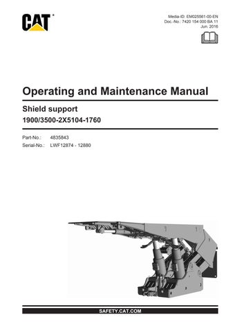
Operating and Maintenance Manual
Shield support
1900/3500-2X5104-1760
Part-No.: 4835843
Serial-No.: LWF12874 - 12880


• Thank you very much for reading the preview of the manual.
• You can download the complete manual from: www.heydownloads.com by clicking the link below
• Please note: If there is no response to CLICKING the link, please download this PDF first and then click on it.

CAT, CATERPILLAR, THEIR RESPECTIVE LOGOS, ”CATERPILLAR YELLOW“ AND THE “POWER EDGE” TRADEDRESS, AS WELL AS CORPORATE AND PRODUCT IDENTITY USED HEREIN, ARE TRADEMARKS OF CATERPILLAR AND MAY NOT BE USED WITHOUT PERMISSION.
© 2016 CATERPILLAR ALL RIGHTS RESERVED
1 About this manual
This chapter contains important information that makes it easier for you to use this manual. You will also get information about the structure of the manual and the symbols, characters and abbreviations used and frequently used terms.
1.1 How to use this manual
applicable operating manual Using an operating manual that was not specifically written for the machine concerned can result in a safety hazard for yourself and others. Ensure that the data on the machine complies with the data given in the operating manual. The operating manual must be accessible at all times to all persons working on or with the shield. It should always be available at the place of operation.
new operating manual Request a new operating manual immediately if the current operating manual is no longer complete or has become illegible.
Persons for whom the operating manual is intended
This operating manual is intended for those persons who work with or on the shields. All persons working on the face, at the edge of the face or at the entry must read this operating manual.
This includes persons who: are in charge of transport, set up the rise heading, perform installation/removal work, operate the shields, correct malfunctions, carry out daily routine work on the face or in the entry, monitor and look after for the hydraulic system, carry out maintenance work, carry out repair work.
Supervisory personnel who: initiate the activities mentioned above and/or supervise them.
Purpose of this operating manual
Efficiency This operating manual is intended to help you work efficiently and safely with our product. It contains important information on all activities relating to the product.
Take the time to read this operating manual in its entirety. Pay particular attention to the respective safety instructions. Familiarize yourself well with the appearance and meaning of the safety and information symbols.
Safety Carefully read through the chapter "Safety". This chapter contains important information indicating possible hazards.
Observe the information given and follow the instructions.
service partner Please contact your service partner for spare part requests or for the clarification of technical questions.
1.2 Signs and symbols used DANGER
The combination of the signal word DANGER and a corresponding symbol warns you of an immediate danger with a high personal risk.
If not observed, you or your coworkers will be seriously injured or killed.
1. Follow the described instructions.
WARNING
The combination of the signal word WARNING and a corresponding symbol warns you of a potential danger with a moderate personal risk.
If not observed, you or your co-workers might be seriously injured or killed.
1. Follow the described instructions.
CAUTION
The combination of the signal word CAUTION and a corresponding symbol indicates a potential personal risk.
If not observed, you or your co-workers could suffer minor to moderate injuries.
1. Follow the described instructions.
NOTICE
The combination of the signal word CAUTION and the adjacent symbol indicates a potential risk of damage to the machine.

If not observed, material damage might occur on the machine.
1. Follow the described instructions.
Tip
The signal word TIP indicates useful tips and information. This information will help you become more familiar with the machine and allow you to prepare your work more exactly.
1. Observe the provided tips and information.
Important information
The combination of the signal words IMPORTANT INFORMATION and the adjacent symbol indicates important information or other operating manuals which must be observed at this place.
1. Observe the information and read the specified operating manuals.
2 Safety
This chapter provides you with important information about your safety. Pay special attention to this chapter. The safety instructions and rules of conduct are intended to help you avoid hazardous situations and perform the necessary work as safely as possible.
2.1 General safety instructions
state of the art
The shield support has been manufactured using state of the art technology and in accordance with the generally recognized safety standards and regulations. You and others can nevertheless still be exposed to dangerous situations, e.g. as a result of environmental influences, machine damage or operator errors. In addition to this operating manual, make sure you also observe the legal provisions and regulations for accident prevention in your country.
Observe the safety and accident prevention regulations of the following parties: the mining company, the mines inspectorate and the mining supervisory authorities.
additional operating manuals Please also read the operating manuals of the components required for operation, e.g. gearboxes, E-motors, etc. carefully and thoroughly. Clarify any questions before starting work.
2.2 Personnel
The machine may only be operated by skilled or instructed personnel.
As a fundamental rule, installation and repair work may only be carried out by personnel who have been adequately trained for these particular requirements.
The following parts may only be installed or repaired by service technicians authorized by Caterpillar or mining professionals as defined below: safety components (pressure relief valves, etc.), the electrical system (controls, signaling devices, etc.), hydraulic system
qualification
A skilled worker is someone who, based on his special training and experience, has sufficient knowledge and is familiar with the relevant regulations. A skilled worker can carry out the work assigned to him. He can recognize potential hazards and take the necessary measures to eliminate them. He also has the required repair and installation knowledge.
An instructed person is someone who has been instructed with regard to the tasks assigned to him and the potential hazards which arise due to improper behavior, and, if applicable, has been trained/instructed concerning the necessary safety equipment and protective measures. The instructed person is able to work while looking ahead, recognize hazards and act accordingly.
2.3 Repair and servicing
In general, repair work may only be performed by persons who have the knowledge and skills to meet the special requirements and have been adequately trained in the repair and servicing of the equipment.
Repair work on and overhaul of: safety devices, as e.g. pressure relief valves, hydraulic props and cylinders control units, valves, and filters may only be carried out by Caterpillar service engineers or by specially trained personnel of the mining company.
2.4 Operating conditions
2.4.1 Intended use
The shield has been designed and manufactured exclusively for use as a shield unit for longwall faces.
Use the shield only as intended!
Intended use includes: propping the roof up against the mine floor, ensuring an adequate travel way, the following shield operations: lowering, pulling up, aligning and setting, the following conveyor operations: advancing, retracting, forming a thrust bearing for: the conveyor and mining equipment, conveyor steering devices, devices for raising the conveyor, conveyor steering cylinders.
Do not make any modifications or carry out changes which could impair safety. All modifications and changes must be approved by Caterpillar. Only use original spare parts from Caterpillar. Note that using parts from other manufacturers will void the guarantee.
2.4.2 Unauthorized use
Applications not expressly listed as intended use represent unauthorized use and are not permitted with the shield.
Unauthorized use includes: pushing the shield back into the caving area, raising the conveyor by means of the hydraulic force of the shield, setting the shield canopy in roof falls.
Further information about this can be found in the "Operation" section of this chapter and in chapter 5 of this manual in the "Operation of the shield support" section.
Caterpillar assumes no liability for damage caused by unauthorized use.
2.5 Using the machine and working on the machine
Each time before you turn on the machine, check that all protective devices are on the machine and functional.
Keep the signaling and lighting systems in proper working order.
Clean the operating plate at regular intervals. Make sure that the operating symbols are clearly recognizable.
Never reach into or enter areas between machine components which can move. Immediately replace damaged components relevant for safety. Shut down the relevant section immediately if component damage creates a hazard and immediate repair is not possible. If there is a safety hazard, secure this area and notify the entire face crew and responsible superiors without delay.
Secure the conveyor against being switched back on again while carrying out:
Maintenance work
Inspection work
Repair work
Notify the responsible personnel of the following prior to working on the longwall:
your exact location, the work you are carrying out how much time you will probably need
You may only carry out work in the mining area if: the roof has been secured against falling rock, the coal face has been secured against collapsing and the mining equipment and conveyor have been shut down and secured against being switched back on.
Refit any protective devices removed immediately after completing work, and check that they are working properly.
emergency stop Press the EMERGENCY STOP switch immediately in the event of faults or irregularities in operation. Notify your supervisor of any peculiarity, so that necessary action can be taken immediately.
Actuate the EMERGENCY STOP SWITCH also if safety equipment.
danger of explosion Make sure to comply with the intervals specified for maintenance and inspections of the conveyor, as hot surfaces might cause an ignition of explosive atmospheres (air) and dust.
Observe the separate operating manuals for the components used.
disconnecting the conveyor Before you disconnect the support from the conveyor, release the load from the components under hydraulic pressure or mechanical stress.
lifting the conveyor
If you raise the conveyor in the area of several shields, the shields to which lifting tackle is attached must not be located next to one another. Reset the shields in the area where the conveyor is to be raised. Check the setting pressure. Under no circumstances should you disengage the canopy from the roof. It must always be in full contact over the entire length.
Only use the provided points of attachment and lifting tackle of adequate loadcarrying capacity. You must under no circumstances use cylinder brackets as they are not designed for tensile loads.
Only lift the conveyor using shields which are connected to the conveyor via the relay bar. Unattached shields could tip over forwards.
travel way
Make sure that the minimum dimensions specified for the travel way with the shield are maintained at all times.
Any equipment subsequently added to the shield, such as steering devices, must not reduce the minimum travel path. It may be necessary to install additional devices in order to ensure that the minimum travel path is maintained.
Storage and transport
Do not store any materials or components in the travel way or in your working area
Only hook the lifting tackle into the lifting points provided for this purpose. Pay attention to the different load limits of the lifting points. Also observe the instructions on the transport sheets. Never attach lifting tackle to brackets and cylinder connections.
Only use means of attachment that are in perfect condition and have been designed for the loads that occur.
For round components use transport straps only. Never use chains or steel cables for this purpose.
Do not damage any finished or polished surfaces, such as shaft surfaces, sealing surfaces, etc.
Make sure that the transport safety devices have been correctly fitted. Secure all moving parts so that they are stationary.
When using floor conveying devices for transport make sure that the center of gravity is as low as possible.
Never walk or stay under unsecured components or suspended loads.
automatic mode
In automatic mode, the shield units of a face are controlled by an automatic program without any human intervention. When traveling along the face you should therefore always bear in mind that the shield units may move automatically. Therefore it is vital that you observe the warnings at the face entries as well as the visual and acoustic signals emitted by the control unit in the shield unit currently operated.
lubricants and chemicals
When working with oils, greases and other chemicals, pay attention to the safety regulations applicable to the product (manufacturer's safety data sheet). Dispose of oil, grease and other chemicals as well as contaminated fluids in accordance with national environmental laws.
2.6 Notes on the hydraulic system
hydraulic system protective devices Note that when dismantling protective devices that include hydraulic components, those components may be pressurized. You could be seriously injured by hydraulic fluid squirting out in an uncontrolled manner. It is therefore imperative that you depressurize the hydraulic components before dismantling the protective devices.
pressure relief valves Take care to ensure that pressure relief valves are always equipped with protective caps. Replace any defective protective caps immediately.
handling hydraulic fluids Avoid direct skin contact with hydraulic fluids. Hydraulic fluid can penetrate the skin and cause dangerous infections.
Never use hydraulic fluids for backflushing or cleaning. Hydraulic fluids are very harmful to your health.
Only persons who have and can demonstrate special knowledge of hydraulics are allowed to work on the hydraulic system (technician).
Carry out a visual inspection of all hydraulic components at regular intervals. In particular, please observe the following:
the hoses are not pinched.
the hoses have no bubbles or blisters.
the hoses or the outer sheaths of the hoses are not abnormally hard. the outer sheath of the hose is not damaged. the connectors are securely inserted into the coupling sockets. the connections are leak-tight.
Make sure that no dirt penetrates the hydraulic system during repair work. Dirt in the hydraulic system can cause serious damage to the entire system. Backflush the hydraulic lines thoroughly before installing them.
Before removing the staples for disconnecting the hose lines, turn the hose at the connector to check whether the line is still pressurized. If the hose is difficult to turn or does not turn at all the line is still pressurized. Do not fail to depressurize the hydraulic line.
If staples are difficult to disconnect or cannot be disconnected, the hydraulic line may still be pressurized. Do not fail to depressurize the hydraulic line.
Always secure the plug connectors of the hydraulic elements with the corresponding staples only. Always fasten the staples completely with both sides. Never use nails, wire or similar materials.
Check all connectors and connections of the depressurized system for leaks after finishing repair work.
Never try to hold a hose line that is thrashing about. Depressurize the section in question immediately.
Never try to repair damaged hose lines.
Replace hose lines at the first suspicion of damage. permissible hose lines Only use hose lines approved for the prevailing pressures.
Do not use any hose lines with damaged connectors or worn O-rings. Replace hose lines only with hose lines of the same or higher quality.
Germany / Europe Mark the crimped-on strip (both sides) using a punch as follows:
manufacturer ID
working pressure
date of manufacture
Caterpillar ID
installing hose lines Lay the hose lines correctly behind the brackets and clips provided for them. For more concise information, follow the "Technical information on hydraulic components".
Australia Mark the crimped-on strip (both sides) using a punch as follows: manufacturer ID working pressure in [bar]

date of manufacture (YY, MM)
Caterpillar ID
Additional writing on the label: manufacturer ID material number number of the test record, date of manufacture of the hose line, date of manufacture of the hose working pressure.
2.6.1 Recommended storage and use period
The following recommendations apply to the use, storage and manufacture of hydraulic hoses and lines:
hose storage period For the manufacture of a hose line, the used hose should not exceed a max. storage period of 4 years.
length of storage time for hose lines
For hose lines, a maximum storage period of 2 years applies (starting from the time of manufacture).
To prevent signs of aging in hydraulic hoses and hose lines, aim for the following storage conditions: store in a dry, low-dust location in a lying position, the storage temperature should lie between +15°C and +25°C at max. 65% relative humidity, do not store below +10°C, avoid direct sunlight or exposure to UV radiation, do not use ozone-forming lights or electrical devices which form sparks in the direct vicinity,
avoid contact with acids, bases or solvents, protect from nearby heat sources, when stored coiled up, the radius of the coils may not be smaller than the smallest bending radius indicated by the manufacturer.
length of use for hose lines The service life of hose lines must meet the requirements of DIN 20066. Hose lines must be checked for damage daily by the operator. The test criteria of DIN 20066 must be observed.
The period of use of hose lines should not exceed a period of 2 years.
Guide values for service life
Tab. 1: Service life
NOTICE
Due to the cold-flow properties (creep) of the hose lines exhibited after installation of the fittings, ready assembled hose lines should be stored for as short a period as possible prior to use.
Determination of the service life by the operator
Notice on work safety
The hydraulic hose line inspection intervals should be adapted to the operating conditions of the mine.
extension The operator can define an extension of the guide values mentioned above. This requires the following measures:
The operator must write a risk and hazard analysis which takes into consideration the protective measures to be implemented in the event of hydraulic hose line failure.
Repeated checks for safe working conditions at appropriate and, if necessary, shortened intervals by qualified personnel.

Notice on work safety
An extension of the replacement interval may not result in a dangerous situation which could cause harm to employees or other persons.
If hydraulic hose lines fail during operation or if damage or faults are found more frequently during regular checks, the checking and replacement intervals should be shortened in addition to finding the cause of the fault.
reduction The operator must define a reduction in the above-mentioned guide values if: inspections show there is significant wear on the hydraulic hose lines, indicating a reduced service life.
• Thank you very much for reading the preview of the manual.
• You can download the complete manual from: www.heydownloads.com by clicking the link below
• Please note: If there is no response to CLICKING the link, please download this PDF first and then click on it.