Operation Manual
SH640 D Roof Support Carrier
Serial Number 5004048
• Thank you very much for reading the preview of the manual.
• You can download the complete manual from: www.heydownloads.com by clicking the link below
• Please note: If there is no response to CLICKING the link, please download this PDF first and then click on it.

This document is the property of Caterpillar SUBJECT MATTER HEREIN IS PRIVATE, CONFIDENTIAL AND RESTRICTED. Do not use, reproduce, copy, distribute or disclose except with, and only to the extent of, prior written consent of Caterpillar PERSONS RECEIVING THIS DOCUMENT ARE RESPONSIBLE FOR RESTRICTING DISCLOSURE, except as absolutely necessary consistent with the intended use. When such is completed, return immediately to Caterpillar.
Caterpillar recommends that all Safe Working procedures should be approved and checked by Mine Officials.
declines all liability for direct or indirect consequences of printing errors.
This document is copyright. All intellectual property rights and copyright in the document (or any part of this document remains the property of Caterpillar. Except as provided for in the Copyright Act 1968 (Ctn) no part of this document may in any form or by any means (including without limitation electronic, mechanical, micro copying, photocopying, recording or otherwise) be reproduced, stored in a retrieval system or transmitted without the prior written permission of Caterpillar.
Section 1
General Information
INTRODUCTION
The operation of heavy mining machinery can be hazardous. To ensure safe operation, operators and personnel must be alert, competent, correctly trained, tested and licensed in the principles, capabilities and correct operating and isolation procedures of the machinery.
This manual is designed to provide the SH640 D Roof Support Carrier operator with the proper information regarding the machine’s instrumentation, operating controls and general safe working procedures. All operators of this machine must be conversant with the information contained within this manual before operating the machine.
To ensure safe and efficient operation, the SH640 D Roof Support Carrier must be adequately maintained by the operators and service personnel. To achieve this, the operator’s pre-start inspection procedure contained in Section 6 of this manual must be performed before any use of this machinery is undertaken.
Any abnormalities should be reported immediately to service personnel to avoid costly machine repairs, production downtime and unsafe operation of the machine.
DESCRIPTION
The SH640 D is a 40000 kg high capacity Roof Support Carrier. It has been designed for lifting and carrying heavy pieces of equipment and machinery in underground coal mines. Its main function is carrying and placing of longwall equipment and shields. The machine comes standard with a set of fork tines and winch for this purpose.
The SH640 D is powered by a 172 kW (230 HP) Caterpillar 3126 turbocharged four-stroke inline six cylinder flameproof diesel engine package. Flameproofing of the system includes a wet bath exhaust conditioning system complete with intake flame traps and dual particulate filtration. The start system is pneumatic. The Diesel Control System (DCS) is an intrinsically safe electronic monitoring system. The engine power output is connected to the constant four-wheel drive system via a drive coupling and converter through a four-speed bidirectional power shift transmission to heavy duty axles with liquid cooled Posi-Stop brakes.
A site specific Risk Assessment is recommended to be conducted before this machine is introduced into service.

SPECIFICATIONS
All specifications are subject to change without notice. Always consult the dealer to obtain current information before applying critical loads.
Overloading equipment could cause personal injury, death or equipment damage. Due to configuration or options these weights can vary up to 20%. Caterpillar recommends that relevant standards and safety procedures should always be used when operating this machine. Removal of protective canopies, doors, interlocks and structures etc., could cause serious injury or death. Replacement with correctly torqued fasteners is mandatory.

Section 2
General Safety and Precautions
This section contains specific safety precautions that shall be followed whilst the machine is being used by suitably qualified operators. This list is NOT all inclusive and a measure of commonsense should always be applied together with established site specific risk assessment and safety procedures.
ONLY TRAINED AND AUTHORISED OPERATORS SHALL OPERATE THIS MACHINE
DO NOT use the machine for any purpose other than its intended use.
DO NOT for any reason exceed the indicated capacity of the machine.
DO NOT operate the machine unless all operator checks and scheduled servicing have been performed. Report any damage or faulty operation immediately and do not operate the machine until the fault has been corrected.
DO NOT tie down or tow equipment such that the chains or slings are not rated for the capacity of the machine and equipment.
DO NOT operate the machine unless:
There are no tags attached stating otherwise.
All covers and guards are correctly installed.
Personal protective equipment is worn.
DO NOT start the machine unless:
There are no tags attached stating otherwise.
The area around the machine is clear.
The park brake is applied.
Transmission is in neutral
All water and oil levels are checked.
All site specific checks are completed.
DO NOT leave the machine unless:
The machine is parked in a safe place.
The transmission is in neutral
The park brake is applied and brake head pressure is zero
The lift arms are lowered.
The engine is stopped.
DO NOT work on the machine in low ventilated areas while the engine is running.
ALWAYS sound the horn before starting the engine to alert anyone who may be around the machine.
ALWAYS ensure that the operator’s compartment door is closed and made secure before operating the machine.
ALWAYS keep head, body and arms inside the operator’s compartment at all times.
ALWAYS travel at low speeds in congested areas. Slow down while travelling around corners and sound the horn frequently in areas of limited visibility.
ALWAYS drive carefully, observing all traffic rules and regulations at your colliery and be in full control of the machine at all times.
Travelling at high speeds, on cross grades or articulating the machine with raised loads may cause the machine to become unstable.
ALWAYS follow the correct isolation and tag out procedure before performing any servicing or accessing beneath or on the machine.
ALWAYS operate carefully and in a responsible manner and observe all Manager’s Transport Rules.
ALWAYS refer to site JSA and SOP’s prior to towing with the machine.
ALWAYS ensure sufficient ventilation is available to dilute exhaust gases, as stated on the machine’ compliance plate.
ALWAYS be aware of the hazard sources on the SH640 D:
Engine coolant pressure (see Section 5).
Engine coolant temperature (see Section 5).
Engine exhaust temperature (see Section 5).
Rotating radiator fan.
Stored hydraulic pressure (see Section 5).
Stored air pressure (Air receiver) (see Section 5).
Engine oil pressure and temperature.
Transmission oil temperature.
Articulation area (see Section 5).
Lift arm area (see Section 5).
Machine mass.
ALWAYS use correct boarding and dismounting procedures:
Check floor.
Hold on, step down.
Three points of contact at all times.
Board using hand holds only, and not the steering wheel.
ALWAYS drive the machine to suit the conditions, report or rectify any holes and ruts, that may cause injury or damage to the equipment.
ALWAYS ensure the area around the machine is clear of personnel when performing machine functional tests. These include lift arm functions, steering, brake release and functional testing of any attachments that may be attached to the machine’s PTO couplings.
ALWAYS allow the engine or machine systems to cool sufficiently prior to commencing any maintenance or service on hot machine components.
ALWAYS be aware of the impact of the payload on the visibility available to the operator. The recommended maximum speed when loaded is 10 km/h, however, the impact of the payload on the operator’s field of vision must be considered when operating the machine with payload. Drive to the conditions.
NEVER operate the machine under unsecured roof.
Keep your machine clean. A clean machine makes for a safer machine.
No diesel engine should be operated underground if it is smoky, running unevenly, or if the exhaust system is not in good condition.
In areas where auxiliary ventilation is used, the operator should make sure fans are operating before starting the machine.
The engine shall not for any reason be left running unattended underground.
The engine should not be shutdown from full load and must be allowed to idle for a few minutes before stopping.
Never operate a machine that you feel is mechanically unsafe.
MACHINE TOP ACCESS
On the off driver’s side of the machine, three foot holds have been installed to aid in safe access to the top of the machine.
Prior to accessing the top of the machine ensure the top surfaces are free of any material that could pose a trip or slip hazard. Maintain three points of access to avoid injury.
Foot Holds

SAFETY LABELS AND INSTRUCTIONS
This manual contains important information affecting the safety of personnel and the equipment being used.
The safety instructions and behavioural rules are intended to protect operators from potentially dangerous situations and assist in the safe operation of the trailer and associated equipment.
The following symbols are used with safety instructions and identify varying degrees of hazardous conditions.
The safety instructions associated with these symbols are to be considered the minimum requirements for effective hazard and operational control.
Points in the text marked with this symbol draw attention to immediately impending danger. Possible consequences are very serious or fatal injury.
These points contain information on potentially dangerous situations. Possible consequences are very serious or fatal injury.
This symbol draws attention to potentially dangerous situations. Possible consequences are light to moderately serious injury and machine damage.
Points in the text marked with this symbol draw attention to potentially harmful situations. Possible consequences are damage to machine or equipment in immediate vicinity


Text marked with this symbol contains useful information associated with the machine and its application.
Section 3
Gauge Parameters and Colour Coding


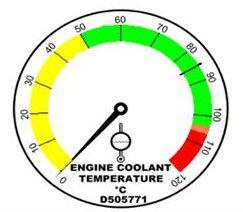
GAUGE COLOUR CODE
The gauges in the operator’s compartment are colour coded to assist the operator to recognise if the temperatures and pressures are within the correct operating parameters. During normal operation some gauges may, at times, read outside of the indicated normal operating range e.g. during normal operation, when the operator applies the brake the brake head pressure gauge will drop below the minimum pressure and indicate that the pressure is too low. This is because the pressure is being released from the brakes to allow the springs to apply the brakes. When the operator releases the brake the gauge should then return to the green zone.
RED: The gauge is indicating an unsafe condition. When this occurs the operator should stop the machine and rectify the problem or have service personnel rectify the problem before placing the machine back in service.
ORANGE: The gauge is indicating a temperature or pressure outside of the normal operating range. The operator should closely monitor the gauge and report the problem to service personnel for rectification.
YELLOW: The gauge is indicating a temperature or pressure below the normal operating range. This will not cause immediate damage if operated for short periods. Report to service personnel for rectification if machine continually operates in this area.
GREEN: The gauge is indicating that the temperature or pressure being monitored is within the normal operating range.
• Thank you very much for reading the preview of the manual.
• You can download the complete manual from: www.heydownloads.com by clicking the link below
• Please note: If there is no response to CLICKING the link, please download this PDF first and then click on it.