OPERATING AND INSTRUCTION I\I\ANUAL

FOR 6. 6KV STARTERS AND SWITCHGEAR
SUPPLIED TO RANSOME & RAPIER PLC
FOR USE ON A W2DOO WALKING DRAG LINE
• Thank you very much for reading the preview of the manual.
• You can download the complete manual from: www.heydownloads.com by clicking the link below
• Please note: If there is no response to CLICKING the link, please download this PDF first and then click on it.


W2000 WALKING ORAGLINE W.1220
Equipment
6.6kV Switchboard Vacuum Contactor VC 186E 10
V-Master Unit
SE 327 Isolator
SO 497 Isolator Inte-rlock and Key Exchange System
LODTRAK Relay
Miniature Circuit Breaker
UC05 Relay
BFGHD 125A Fuses
Ca 10r Emag Iso la tor
Starting Reactor
Outl ine Drawing
Schematic Drawing
6.6kV Field Switch
600A Vacuum Interrupter
Surge Arresters
Cable Couplers
CEE ITG 7361 Relay
CEE ITG 7011 Relay
Crompton Phase Balance Relay
Crompton Voltage Relays
MTE 4N8 Range
Capacitor T ripping Device Outline Drawing
Schematic Drawing
INDEX
Instruction Sheet Reference
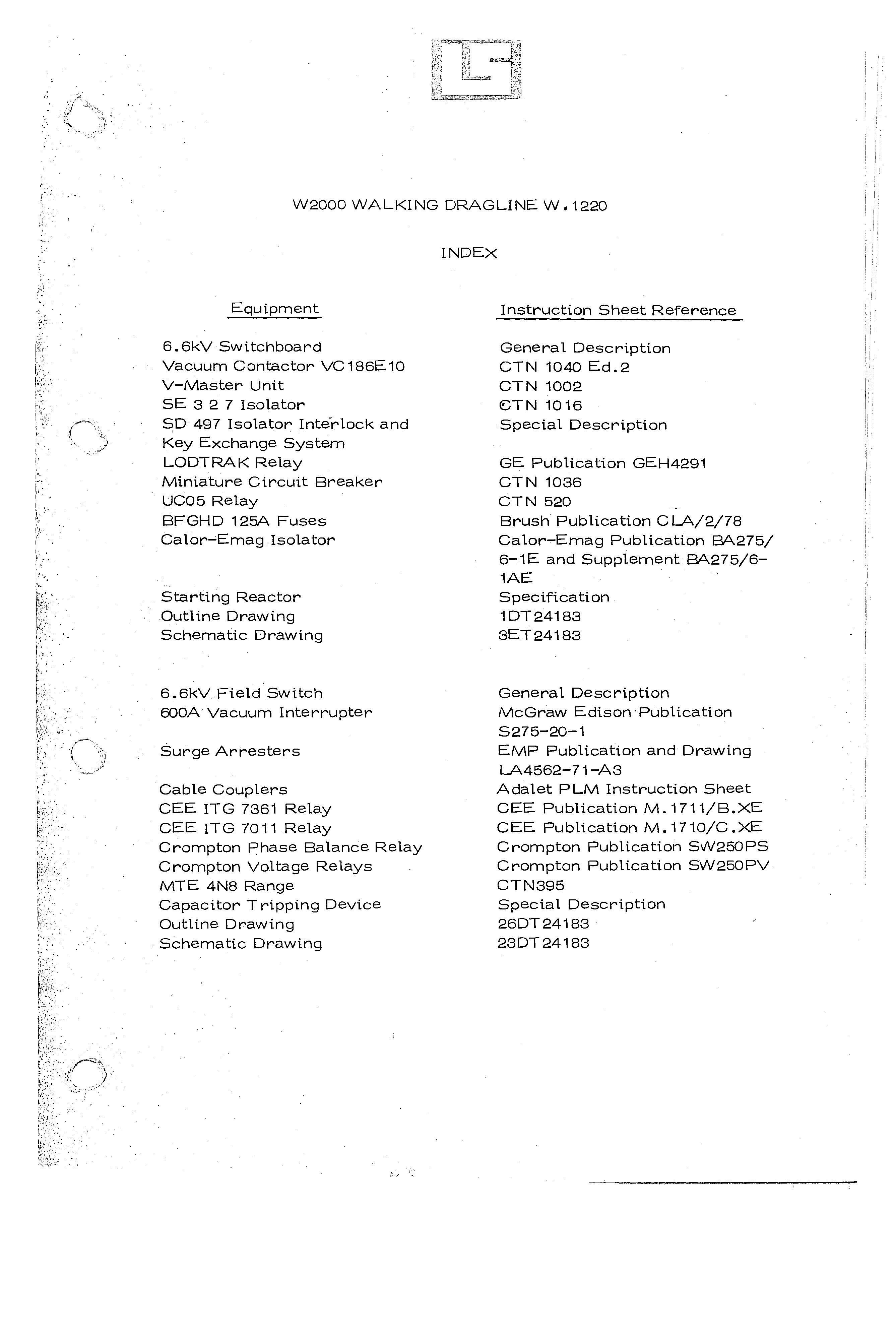
Genera 1 Description
CTI\I 1040 Ed.2
CTN 1002
CSTN 1016
Special Description
GE Publication GEH4291
CTN 1036
CTN 520
Brush Publication CL6./2/78
Calor-Emag Publication B£:>..275/
6-1E and Supplement B£:>..275/6-
1AE
Specification
1DT24183
3ET24183
General Description
McGraw Edison Publication
S275-20-1
EMP Publication and Drawing
L6.4562-71-A 3
Adalet PLM Instruction Sheet
CEE Publication M. 1711/B.XE
CEE Publication M. 1710/C .XE
Crompton Publication SvV250PS
Crompton Publication SW250PV
CTN395
Special Description
26DT24183
23DT24183

Loadline 'D' Frame Me B
550KVA Transformer Outline Drawing Schematic Drawing
Earthing Transformer Outline Drawing
Dorman Smith Publication
IMD/6/83
Specification
21DT24183
22BT24183
S pecifica tion
T24183 12/83

6600V SWITCHBOARD
The 6600v switchboard is constructed in Laurence Scott & Electromotors (Wolverhampton) Ltd Type D Enclosure as shown on outline drawings 1DT24183/4.
The panel is arranged as follows:-
INCOMER with cable entry
SYNCHRONOUS MOTOR NO.2 starter
REACTOR
SYNCHRONOUS MOTOR NO. 1 Starter
AUXILIARY TRANSFORMER feeder compartment with cable exit
Operation and Maintenance instructions are included in the text of this Manual for the major individual .cQmponents which comprise the swi tchboard.
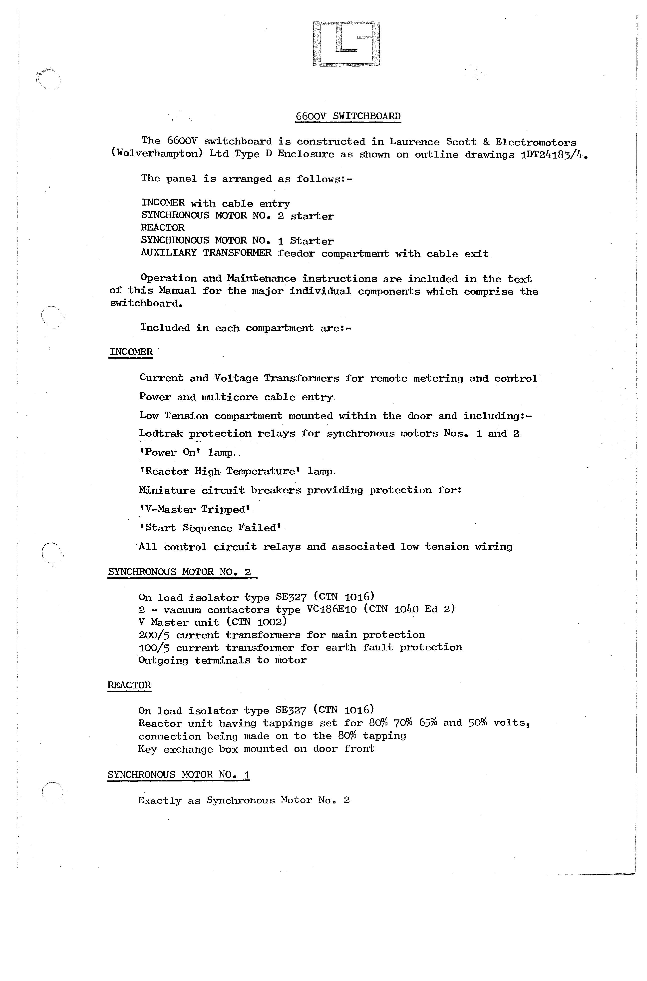
Included in each compartment are:-
INCOMER -
Current and Voltage Transformers for remote metering and control
Power and multi core cable entry.
Low Tension compartment mounted within the door and including:-
Lodtrak protection relays for synchronous motors Nos. 1 and 2.-
'Power On' lamp.
'Reactor High Temperature' lamp.
Miniature circuit breakers providing protection for:
'V-Master Tripped'.
'Start Sequence Failed'.
'All control circuit relays and associated low tension wiring.
SYNCHRONOUS MOTOR NO.2
On load isolator type SE327 (CTN 1016)
2- vacuum contactors type VC186E10 (CTN 1040 Ed 2)
V Master unit (CTN 1002)
200/s current transformers for main protection
100/s current transformer for earth fault protection
Outgoing terminals to motor
REACTOR
On load isolator type SE327 (CTN 1016)
Reactor unit having tappings set for 80% 70% 6S% and So% volts, connection being made on to the 80% tapping Key exchange box mounted on door front
SYNCHRONOUS MOTOR NO.1
Exactly as Synchronous Motor No. 2

AUXILIARY TRANSFORMER
Set of :3 - Brush BFGHD 125A 6.6kV fuses
Calor-Emag 400A fault making load breaking isolator with shunt trip actuated by fuse striker pins.
Mounted on the door front are:-
'Fuse Blown' indicating lamp
Key Exchange Box
GENERAL
anti-condensation heaters are provided in each compartment which are powered from a remote L.T. switchboard of separate manufacture.
OPERATION
Provided all isolators are in the 'ON' position for Synchronous Motors 1 and 2 and Reactor compartments then these motors may be started remotely from the appropriate pushbuttons shown on diagram
Interlocks are included in the control circuit to prevent both motors from being started simultaneously.
In the event of a fault developing in the motor/s signals are passed to the Lodtrak relays which in turn will cause an alarm to be sounded. The motor/s are·then stopped at the discretion of the operator.
Should the Reactor become overheated or a fault develop in the vacuum contactor giving rise to V-Master operation then the control circuit will inhibit any further starts of the affected motor. Indication of these conditions is given by operation of the appropriate miniature circuit breaker located on the INCOMER compartment together with a warning lamp in the case of a Reactor High Temperature condition.
KEY EXCHANGE SYSTEMS
There are two key exchange systems associated with the operation of the switchboard.
Internal System
This system is fully described in the Section ISOLATOR INTERLOCK SYSTEM and allows access only to compartments Synchronous Motors 1 and 2 and Reactor.
WARNING: DURING ANY MAINTENANCE OPERATION TO BE CARRIED OUT ON THESE THREE COMPARTMENTS IT SHOULD BE REMEMBERED THAT THE OVERHEAD BUSBARS MAY BE ENERGISED.

External System
This system is concerned with access to compartments 'Incomer' and 'Auxiliary-Transformer' on the switchboard and also to the remote locations 'Collector Door' and 'Lightning Arrester'. The associated KeyExchange Box comprises five figure locks and keys arranged in one horizontal row and is mounted on the door of the 'Auxiliary Transformer' compartment.
The key exchanQe box is designed to release 4 figure keys after the insertion and turning of a single MASTER KEY. The 4 - keys known as LINE keys are used to obtain access to the locations described above.
The MASTER Key is obtained from the Field Switch Housing and is released only when the Field Switch Vacuum Interrupter is in the OPEN position.
Once the MASTER Key has been used in the Key Exchange Box the four line keys are released sequentially. The first two keys to be released are intended for use at the 'Collector Door' and 'Lightning Arrestor' locations. The remaining two keys are for use on the switchboard.
NOTE
The operation of the two key exchange systems are mutually exclusive.
Maintenance
Reference should be made to the individual component manuals for maintenance instructions.


SUPERVAC VACUUM CONTACTORS TYPE Vet8 and VC1 9 (BEIO)
Introduction
Supervac vacuum contactors are manufactured by Toyo Denki Seizo K.K., Yaesu Mitsui Building, No. 7-2, 2-Chome, Yaesu, Chuo-ku, Tokyo, Japan anc are available from Laurence, Scott & Electromotors [Wolverhampton) Ltd, Moorfield Road, Wolverhampton, WV2 4PE.
Description
1. Supervac contactors type VC18 (electrically held) and type VC19 (latched) consist essentially of three vacuum switch valves, a magnet operating mechanism and auxiliary switches all assembled into a steel frame. Fig. 1 shows the general arrangement and names the principal part9.
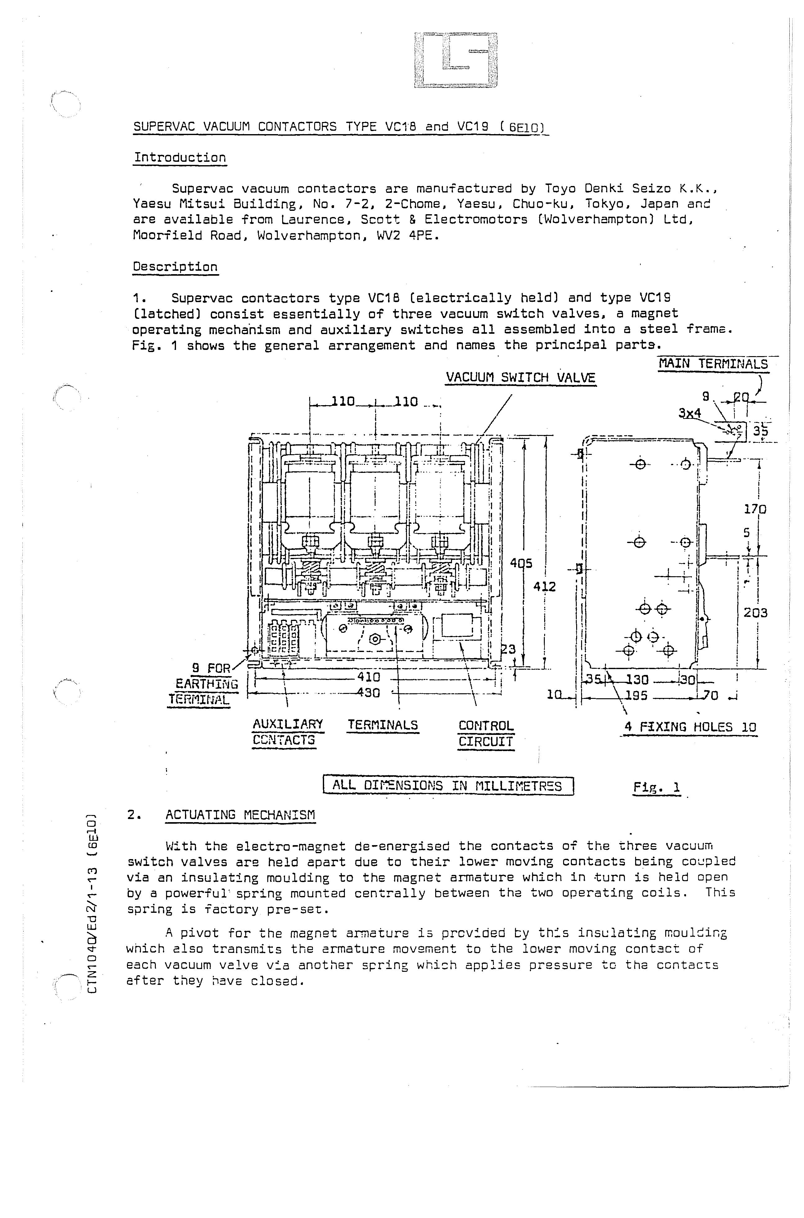
2. ACTUATING MECHANISM
-::;MA:-="I=:N-=-=T=E=RMC":":r=rJALS TERMINALS
VACUUM SWITCH VALVE
I ALL Dlf.£NSIONS IN MILLIMETRSS I Fig. 1
With the electro-magnet de-energised the contacts of the three vacuum switch valves are held apart due to their lower moving contacts being via an insulating moulding to the magnet armature which in turn is held open by a powerful' spring mounted centrally between the two operating coils. This spring is factory pre-set.
A pivot for the magnet armature is prcv:ded ty th:s moulsing which also transmits the armature movement to the lower mOVing contact of each vacuum valve v:a another spring whish applies pressure to the ccntacts after they have closed.
• Thank you very much for reading the preview of the manual.
• You can download the complete manual from: www.heydownloads.com by clicking the link below
• Please note: If there is no response to CLICKING the link, please download this PDF first and then click on it.