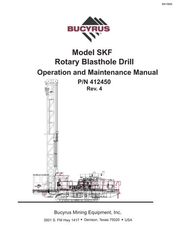
Operation and Maintenance Manual Model SKF Rotary Blasthole Drill Bucyrus Mining Equipment, Inc. 3501 S. FM Hwy 1417 Denison, Texas 75020 USA P/N 412450 Rev. 4 BI615855
• Thank you very much for reading the preview of the manual.
• You can download the complete manual from: www.heydownloads.com by clicking the link below
• Please note: If there is no response to CLICKING the link, please download this PDF first and then click on it.

CLICK HERE TO DOWNLOAD THE COMPLETE MANUAL
CLICK HERE TO DOWNLOAD THE COMPLETE MANUAL
PARTS ORDERINGAND PRODUCT SUPPORT
Use only genuineBucyrus parts in the maintenance, rebuild or repair of these machines.The manufacturer shall have no liability as to any unauthorized modification of machines or parts. The manufacturer is also not obligated or liable for a machines or parts that have been improperly handled; that have not been operated, maintained or repaired according to furnished manuals or other written instructions, and that have been operated with other than genuineBucyrus parts or authorized OEM components.
IDENTIFICATION OF THE MACHINE
Always furnish the Model Number and Serial Number when ordering parts.This information is found on the machine nameplate.
PART NUMBERAND DESCRIPTION
In addition to the Model and Serial Number, always give the part number and description of each part ordered. If there is any doubt as to the correct part number and description, furnish a dimensioned sketch or return the part to be replaced, transportation charges prepaid.Your cooperation in furnishing as much information as possible will assist us in filling your orders correctly and in the shortest possible time.
SHIPMENT
Unless otherwise instructed, all shipments will be made via motor freight collect, freight forwarder or UPS prepaid and charged on our invoice. Shipments cannot be made on open account until your credit has been approved by our accounting department.
PARTS ORDERING
In NorthAmericaTelephone 1-800-854-9030
orTelefax 1-800-582-6570
Telephone (903) 786-2981
Telefax (903) 786-6407
PRODUCT SERVICEANDWARRANTY
In NorthAmericaTelephone 1-800-258-0009
Telephone (903) 786-2981
Telefax (903) 786-6408
Bucyrus Mining Equipment, Inc.
3501 S. FM Hwy 1417, Denison,TX 75020 www.bucyrus.com
© 2010Bucyrus International, Inc.
All Rights Reserved
BI615855
Safety Information
This safety alert symbol indicates important safety messages in this manual. When you see this symbol, carefully read the message that follows and be alert to the possibility of personal injury or property damage.
Before Starting Engine, Study Operator’s Manual
* Read and understand the warnings and cautions shown in Section 1
* Practice All Safety Precautions
* Make Pre-Operations Check
* Learn Controls Before Operating
It is Owner/Operator’s responsibility to understand and follow manufacturer’s instructions on machine operation and maintenance, and to observe pertinent safety precautions, laws and regulations.
California Proposition 65 Warnings
The following warning applies to equipment supplied with lead-acid batteries:
Battery posts, terminals and related accessories contain lead and lead compounds, chemicals known to the State of California to cause cancer and reproductive harm. Wash hands after handling.
The following warning applies to equipment supplied with diesel powered engines:
Diesel engine exhaust and some of its constituents are known to the State of California to cause cancer, birth defects, and other reproductive harm.
Drill Model : ___________________________________
Drill Serial No. : ________________________________
Date Delivered : ________________________________
Dealer : _______________________________________
Customer : ____________________________________
The descriptions and specifications contained in this manual were in effect at the time of printing. The right is reserved to make changes at any time without notice and without obligation.
Introduction i
2/14/2011
BI615855
Safety Stand Placement
Support (Jack Stand) Guidelines for Rotary Drills
SKSW AND SKSS
REQUIRES ADDITIONAL SAFETY SUPPORTS,
PLACE SUPPORTS (JACK STANDS) AS CLOSE TO LEVELING JACKS AS POSSIBLE. THESE AREAS
IF DURING MAINTENANCE MACHINE SUPPORT THE MACHINE DURING DRILLING OPERATIONS.
SKF AND SKFX
NEVER SUPPORT THE MACHINE BY PLACING
NOT STRUCTURALLY ROBUST AND ARE NOT INTENDED OR COOLER SUPPORT DECK. THESE AREAS ARE SUPPORTS UNDER MEMBERS OF THE REAR DECK
TO SUPPORT THE ENTIRE MACHINE WEIGHT.
ii Introduction
BI615855
Product Description
WARNING
DO NOT use this machine for any other purpose than blasthole drilling. The SKF series rotary blasthole drills are designed for blasthole drilling purposes only.
Any other use could result in personal injury, property damage and will void the warranty.
The SKF blasthole drill is specifically designed for Blast Hole Drilling Operations.
The Series SKF are crawler mounted drill rigs, which consist of two (2) major assemblies:
1.Rotary Drill Assembly
2.Excavator Type Undercarriage (Crawlers)
The Rotary Drill assembly is made up of the Engine Package, Compressor Package, Hydraulic System, Rotary Drive, Pulldown and Hoisting System and Drill Pipe Handling mechanism.
The Crawlers are powered by two (2) hydrostatic motors. Each Crawler has its own independent, variable and reversible speed control, and is equipped with 33.5 inch (85 cm) wide triple cleated grousers.
Manual Contents
This manual is furnished with the SKF Series Blasthole Drill to acquaint you with the correct operating procedures and to provide the necessary daily equipment maintenance information required to maintain your machine in a reasonable condition.
NOTE
This manual should be considered a permanent part of the machine and must remain with the machine at all times.
The instructions in this manual are not intended to cover all details about this machine, nor do they intend to provide for every possible contingency that may be encountered in connection with the daily operation or maintenance of this machine.
Should further information be desired or should particular problems arise which are not covered sufficiently in this manual, the matter should be referred to the manufacturer.
Conponent Locations
The following pages highlight the major components and their locations on the drill. Due to the variety of drill options and requirements, each drill may vary from the configurations shown.
Introduction iii
BI615855
SKF Component Locator
FRONT OF MACHINE
COMPRESSOR OIL COOLER
HYDRAULIC OIL COOLER
ENGINE RADIATOR
ENGINE AIR FILTER
LH FRONT JACK
MAST ACCESS LADDER
AIR COMPRESSOR
MUFFLER
DRIVELINE
DUST COLLECTOR
CHARGE FILTERS (LOOP FILTERS OPTIONAL)
MAST ELEVATING CYLINDERS
LH REAR JACK IN DECK PLENUM CHAMBER
PIPE CAROUSEL IN DECK TOOL BOX
CRANE (OPT)
DRILLING PLATFORM VIEWING HATCH
CRANE CONTROLS (OPT)
COMP. AIR CLEANER
RH FRONT JACK
COMPRESSOR AIR/OIL SEPARATOR
FUEL TANK
DIESEL ENGINE
FUEL FILL
PUMP DRIVE
RETURN FILTERS
HYDRAULIC OIL RESERVOIR
MAIN ELECTRIC CABINENT
PRESSURE/VACUUM FILTER
RH REAR JACK
WINDOW WASHER BOTTLE
OPERATOR’S CAB
A/C CONDENSER
iv Introduction
BI615855
Introduction v
SKF Component Locator
TRACK FINAL DRIVE
BATTERY BOX
CRAWLER
A/C/ UNIT
DUST CURTAINS
CAROUSEL
ROTARY DRIVE
LIGHTS
TOP MAST SHEAVE
BI615855
HYDRAULIC OIL FILL PUMP
SKFX Component Locator
FRONT OF MACHINE
MAST REST
WATER TANKS BOLTED UNDER DECK
LEFT FRONT JACK
COMPRESSOR AIR CLEANER
AIR COMPRESSOR
ENGINE MUFFLER
ENGINE COOLER
BATTERY BOX
FLEX DRIVE COUPLING (COVER REMOVED)
PUMP DRIVE GEARBOX
FUEL TANKS BOLTED UNDER DECK
MAIN HYDRAULIC PUMPS
DRILL STEM THREAD LUBRICATOR
LEFT REAR JACK
DRILLING PLATFORM
AIR/OIL RECEIVER TANK
RIGHT FRONT JACK
ENGINE AIR CLEANER
OIL INJECTION TANK
FRONT FUEL TANK
COMPRESSOR OIL COOLER
ENGINE
CENTRAL LUBE SYSTEM PUMP
REAR FUEL TANK
HYDRAULIC FILL HAND PUMP
MAIN RETURN FILTER
CASE DRAIN FILTER
HYDRAULIC TANK
RIGHT REAR JACK
OPERATOR’S CAB
vi Introduction
BI615855
ROTARY DRIVE GEARBOX
SKFX Component Locator
TOP SHEAVES
TRAVELING SHEAVES
MAST
HYDRAULIC FILL HAND PUMP
MAST ELEVATING CYLINDERS
BOTTOM SHEAVES
FINAL DRIVE
CARRIER ROLLERS
TRACK ROLLERS
CRAWLER ASSEMBLY
TENSIONER IDLER
FRONT IDLER
Introduction vii
BI615855
viii Introduction Contents INTRODUCTION SAFETY ....................................................................................SECTION 1 OPERATOR CONTROLS .............................................................SECTION 2 LUBRICATION AND PREVENTIVE MAINTENANCE........................SECTION 3 OPERATING INSTRUCTIONS ...................................................... SECTION 4 DRILLING PRACTICES ...............................................................SECTION 5 MACHINE TRANSPORT AND SPECIFICATIONS...........................SECTION 6 OPTIONS AND ACCESSORIES ...................................................SECTION 7 BI615855
Maximum Wind Speed = 75 MPH (120.8 Km/h) at which time drilling must be stopped, mast lowered and machine shutdown.
Safety 1-1 Safety Section 1
BI615855
Hazard Classification
The Rotary Blasthole Drill is a heavy moving machine with a mast which raises vertically for drilling. Like all moving objects and reach extending devices, there are potential hazards associated with its use. These hazards will be minimized if the machine is properly operated, inspected and maintained. Operator's must read this manual and have been trained to use the machine in an appropriate and safe manner. Non-English speaking persons must have an interpreter explain all safety and operating procedures in this manual. Should any questions arise concerning the maintenance or operation of the machine contact the manufacturer at 1-800-258-0009
Safety Alert Symbol
The safety alert symbol is used to alert you to potential personal injury hazards. Obey all safety messages that follow this symbol to avoid possible injury or death.
Hazard Classification
A multi-tier hazard classification system is used to communicate potential personal injury hazards. The following signal words used with the safety alert symbol indicate a specific level of severity of the potential hazard. All are used as attention-getting devices on decals and labels fixed to the machine to assist in potential hazard recognition and prevention.
Indicates an imminently hazardous situation which, if not avoided, will result in death or serious injury.
Indicates a potentially hazardous situation which, if not avoided, could result in death or serious injury.
Indicates a potentially hazardous situation which, if not avoided, may result in minor or moderate injury.
Indicates a potentially hazardous situation which, if not avoided, may result in property or equipment damage.
1-2 Safety
Safety Alert Symbol
Red
Yellow Blue BI615855
Orange
Overview of Potential Hazards
Potential Hazard Prevention
Crush Hazard. Falling objects can cause severe injury or death.


Do not exceed hoist capacity & stay away from lifted loads. (3500 lbs./1587 kg.) Do not use damaged cable.


Crush Hazard. Falling pipe carousel can cause severe injury or death.
Place carousel against lower stops before servicing hydraulic circuit. Purge air from circuit after servicing carousel circuit.
Entanglement Hazard. Death or serious injury can result from contact with rotating drivelines.
Keep clear of rotating drivelines. Switch off engine before performing service. Do not operate with guard removed.
Entanglement Hazard. Rotating parts can cause personal injury.
Keep away from fan and belt when engine is running. Stop engine before servicing.

Crush Hazard. Falling mast can cause severe injury or death.


Purge air from circuit after servicing mast raising cylinder(s).
Burn Hazard. Hot pressurized fluid can cause severe burns.
Allow to cool before opening.

Safety 1-3
BI615855
• Thank you very much for reading the preview of the manual.
• You can download the complete manual from: www.heydownloads.com by clicking the link below
• Please note: If there is no response to CLICKING the link, please download this PDF first and then click on it.
CLICK HERE TO DOWNLOAD THE COMPLETE MANUAL
CLICK HERE TO DOWNLOAD THE COMPLETE MANUAL