DRAGLINE
Ransomes & Rapier p.l. c.
P.O. Box 1 WATERSIDE WORKS ·IPSWICH IP28HL ENGLAND
Telephone: Ipswich 56383 Telex: 98176
Cables: Rapier, Ipswich
The policy of Ransomes and Rapier p. I. c. is one of continual improvement and, whilst every effort is made to ensure that this publication is up to date and correct in all respects, the right is reserved to change designs and specifications at any time without notice.

• Thank you very much for reading the preview of the manual.
• You can download the complete manual from: www.heydownloads.com by clicking the link below
• Please note: If there is no response to CLICKING the link, please download this PDF first and then click on it.

Introduction
Machine data
PART DESCRIPTION
PART 2 OPERATING INSTRUCTIONS
PART 3 ROPE HANDLING &I INSTALLATION
PART 4 MAINTENANCE .PART 5 BOOM ANGLE &I BOOM HOIST
Alphabetical index

Introduction

General
The RAPIER W700E is an electric walking dragline built to a modular design which facilitates dismantling, highway transport and rC3-erection when changing si tes.
The machine consists basically of a base and a rotate frame with hoist, drag and swing gear, walk mechanism, boom and bucket.
BASE
The base is a circular structure which provides the machine with a large loadbear ing surface. The base centre post is the axis of the rotate frame and transmits the drag force to the base when digging.
ROTATE FRAME
The rotate frame, which carries the boom, machinery and operator1s cab, is supported on a roller ring assembly on the base.
DRIVES
The machine is powered by a motor-generator set.
The motor drives the hoist and drag drums (when operating in the DIG mode) via a torque converter, transmission gearbox, and the drum gears and clutches.
A dog-clutch on thehoist drum shaft transmits the drive to the walk shaft (when operating in the WALK mode) via a train of gears; eccentrics at each end of the walk shaft impart the walk motion to the two walk legs and shoes.
The torque converter incorporates a modul ated cl utch, providing the operatQr with a precise and continuously variable control of speed.
The d. c. generator powers the two reversible swing motors which drive the swing pinions via reduction gearboxes. The swing pinions engage a circular rack on the machine base and so impart swing motion to the rotate frame. Con.trol circuitry provides the operator with precise and continuously variable control of swing speed in either direction, while dynamic braking brings the rotate frame rap idl y to rest when the operator's control is returned to neutral.
A transformer provides a 3-phase supply for the cooling fan motors, pumps, etc; a single phase supply, derived from this 3-phase supply, energizes the a. c. control circuits.
BOOMS, BUCKETS
ro I A choice of three boom lengths is available and the machine can be rigged for any one of three boom angles. A choice of bucket sizes is also available, depending > on boom length and angle.
THE OPERATORS MANUAL
This Manual c;omprises four Parts, preceded by a Machine Data section and followed by an Alphabetical Index.
The Machine Data section relates to an individual machine, specified by the Machine Number and the Customer's Name. It provides working data and an abridged specification, recommended lubricants, etc. At the end is a list of Publ ications, produced by the Suppl iers of certain pieces of incorporated equipment, which are referred to in the main text. Copies of these Publ ications are suppl ied with the machine.
Parts 1-5 of th is Manual are general, cover ing all the standard variations of boom length, boom angle, bucket capacity, etc.
Part 1 gives a general decription of the machine, power flow diagrams and brief details of the compressed air, electrical and automatic lubrication systems.
Part 2 describes the various controls and instruments, start-up, shut-down and emergency procedures, and how to operate the machine.
Part 3 covers rope handl ing and install ation.
Part 4 covers preventive ma intenance and includes a routine ma intenance ' schedule and details of the various lubrication and adjustment procedures. Technical information on the compressed air, electrical and automatic lubrication systems is also included in this section to facil itate faul t-finding.
Part 5 covers the boom angle variations and the boom hoist systems.
The comprehensive Alphabetical Index provides a useful reference to the whole contents of the Manual.
At the end of this Manual, prOVISion is made for the insertion of Appendices to cover changes in design, special customer requirements, etc, which may occur subsequent to the publ ication of this issue.
Safety
WARNING TO OPERATORS AND MAINTENANCE PERSONNEL
This Operators Manual is intended for the guidance of operators and individuals responsible for the maintenance of this machine. It is essential that operators famil,iarize themselves with the controls and operating techniques before making any attempt to operate the machine. Precautions detailed throughout the Manual must be strictly observed.

OPERATING WITHIN MANUFACTURER'S LIMITS
It is the responsibility of the operator to ensure that the machine is operated within the Manufacturerls limits; on no account should the specified maximum digging depth, dump height or suspended load be exceeded.
CHANGING BOOM ANGLE
When changing the boom angle, it is essential for the boom to be properly supported on suitable blocks or trestles when lowered to the horizontal.
DANGER FROM OVERHEAD ELECTRIC LINES
The following safety precautions must be strictly observed. Regard every overhead I ine as being elec trically charged unless you have it in writing from the Electricity Authority that it is not.
Extreme care must be taken when the machine has to operate near overhead lines which cannot be made dead, since inadvertent rotation of the boom may introduce danger. It shoul d al so be remembered that a dangerous condition can arise even when the boom is several feet away from the overhead line.
Where digging or dumping must be carried out in close proximity to overhead electric I ines, take spec.ial care to ascertain the height and distance of the overhead lines. Remember that it is difficult to estimate the he ight of I ines by normal methods of observation.
DANGER FROM ASBESTOS DUST
Clutches and brakes should be cleaned either by vacuum cleaning or by wiping with a damp cloth. Cleaning by compressed air or with a dry brush must be avoided. Any dust or particles which may have accumulated on the workbench or floor should be removed by vacuum cleaning or, alternatively, damped thoroughly before being swept up and placed in dustproof bags for disposal.
WELDING PRECAUTIONS
The earth electrode must be connected directly to the item being welded to local ize the welding current and so prevent damage to other parts of the machine.


Machine data·
Model RAPIER W700E WALKING DRAGLINE
Machine number_9 4 O7
Customer LONDON BRICK COMPANY
STEWARTBY ENGLAND
Working data
Boom length 50·4m (165ft 5in)
A Centre of rotation to boom foot 3.2 m (10ft 6 in)
B Boom foot to ground 4m (13ft 1 in)
C Rear end clearance radius 10. 9m (35ft 9 in)
o Operating radius 45. 5m (149ft)
E Maximum dump height 19.5 m (64 ft)
F Maximum digging depth 32 m (105 ft)
G Overall height to boom point (34 m (111 ft 6 in)

.' .. Basic machine specification

Power unit: 933 KW{l250 hp) a.c. induction motor, site supply of 6.600 V, 3 phase, 50 hertz.
Boom length 50.4 m (165 ft 5 in) Boom angle 350
Mast length 22 m (72 ft 2 in)
Nominal bucket capacity 9. 17 m 3 (12 yd 3 )
Maximum suspended load 29,470 kg (65,000 Ib)
Ground bearing pressure (average) O. 886kgf/cm 2 (12. 6Ibf/in 2 )
Base bear ing area 63. 6m 2 (685 ft 2 )
Shoe bear ing 38 m 2 (409 ft 2 )
Overall length (over fairlead, less boom) 18.5 m (60 ft 9 in)
Width over shoes 14. 3m (46 ft lOin)
He ight to house top (over rope cowl) 8. 8m (29 ft 0 in)
Tonnes Tons (Imp.) Tons (U. S.) Working weight (excl. bucket) 535 526.6 590 Net shipping weight (excl. 447 440 493 bucket and counterweights) Counterwe ights supp lied 88 86.6 97 with machine: total weight
BASE 3-Section, fabricated steel base supporting I ive roller ring and rotate gear rack.
Outs ide diameter 9m (29 ft 6 in)
Roll er circle diameter 8.8 m (28 ft lOin)
Rack diameter 7.4 m (24 ft 5 in)
ROTATE FRAME
Modular construction, comprising five fabricated steel modules assembled with bolted attachments to form complete rotate frame with upper and lower decks. Rota te frame supported on I ive roller ring.
Overall length 15.0 m (49 ft 2 in)
Overall width 11.2 m (36 ft 9 in)
Frame depth 2m (6 ft 7 in)
ro I LL
Rear module
Power module
Supports the motor generator (M. G.) set, torque converter and transmission gearbox, the torque converter oil coolers and the high voltage (H. V.) sWitchgear.
Walk module
Supports the walk shaft and gear ing and the electric control centres.
Swing module
Supports the two swing motors and gearboxes and the air compressor assembly.
Front module
Supports the boom and mast feet, air receivers and the fairlead assembly.
HOIST AND DRAG UNIT
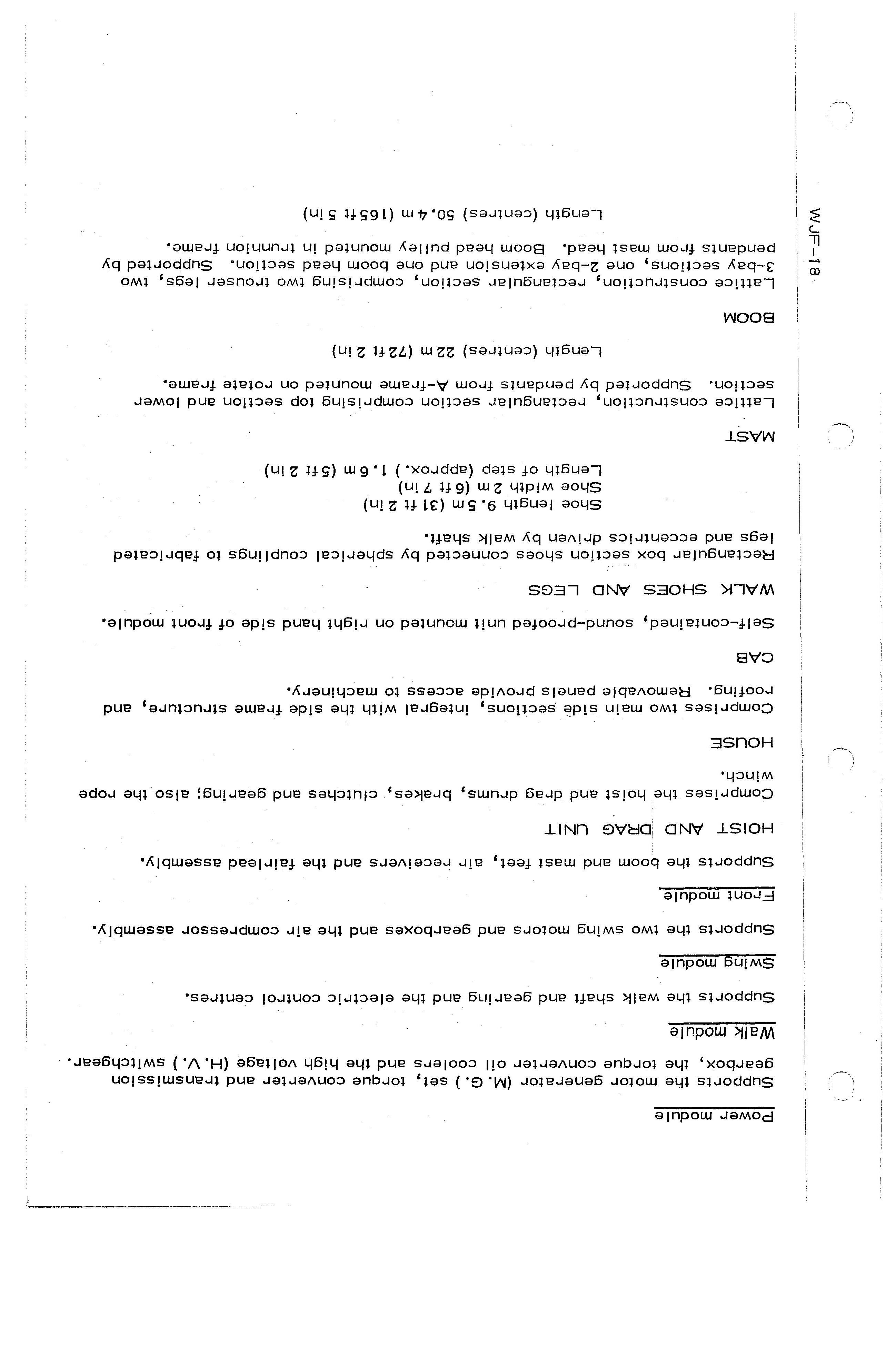
Comprises the hoist and drag drums, brakes, clutches and gearing; also the rope winch.
HOUSE
Comprises two main side sections, integral with the side frame structure, and roofing. Removable panels provide access to machinery.
CAB
Self-contained, sound-proofed unit mounted on right hand side of front module.
WALK SHOES AND LEGS
Rectangular box section shoes connected by spherical coupl ings to fabricated legs and eccentrics driven by walk shaft.
Shoe length 9.5 m (31 ft 2 in)
Shoe width 2m (6 ft 7 in)
Length of step (approx.) 1.6 m (5 ft 2 in)
MAST
Lattice construction, rectangular' section comprising top section and lower section. Supported by pendants from A-frame mounted on rotate frame.
Length (centres) 22 m (72 ft 2 in)
BOOM
Lattice construction, rectangular section, comprising two trouser legs, two 3-bay sections, one 2-bay extension and one boom head section. Supported by pendants from mast head. Boom head pulley mounted in trunnion frame.
Length (centres) 50.4m (165ft 5 in)
Mechanical data

TORQUE CONVERTER
Incorporates input gearbox, modulated clutch and torque converter. Output speed controlled by operator via modulated clutch.
Input speed 1500 rev/min
Output speed (DIG mode) 0- 2000 rev/min
Output speed (WALK mode) 0- 1200 rev/min
TRANSMISSION GEARBOX
Double reduction, oil bath lubrication with forced lubrication to bearings.
Overall input/output ratio 9. 19 :1
TRANSMISSION BRAKE
Spring-appl ied, air-released, 3-call iper, triple disc type, on extension of transmission gearbox input shaft.
DRUM GEARING
Intermeshing hel ical hoist and drag drum gears; drag drum gear driven via hel ical pinion. Automatic grea;;e lubrication of open gears.
Input/output ratio 6.05 :
DRUM CLUTCHES
Air-engaged, internal contracting, tube type drum.clutches.
Tube volume 42370 cm3 (2585 in3)
Max. air pressure 10. 55kgf/cm 2 (150 Ibf/in 2 )
DRUM BRAKES
External, contracting band brakes; air operated during service but with springapplied safety facilities. Forced air cooled.
WALK CLUTCH
Dog ·clutch, air engaged and disengaged by double-acting air cyl inder.
WALK GEARING
Double reduction spur gear train, driven from hoist shaft via walk clutch. Automatic grease lubrication of open gears.
Overall input/output ratio 8.40 :1
WALK BRAKE
Spring-appl ied, air-released contracting shoe brake on extension of 1 st walk pinion shaft.
SWING GEARBOXES
Double reduction, oil bath lubrication with forced lubrication to bearings.
Overall input/output ratio 28.31 :1
SWING BRAKES
Spring-app'lied, air-released, contracting shoe brake on swing motor shaft extens ion.
SWING PINIONS AND ROTATE GEAR RACK
Rack spur gear (16 sections) bolted to base. Swing pinions spl ined to output shafts of swing gearboxes.
Overall ratio 21.82 :1

LIVE ROLLER RING
Comprising 132 flanged rollers, mounted in 12 sections (11 rollers per section) bolted together to form complete ring.
SUSPENSION ROPES
Pendant system comprising eight ropes complete with end fittings.
HOIST AND DRAG ROPES
Electrically dr iven, reversible winch for reeving hoist and drag ropes.
SERVICE HOIST
Electrically driven hoist, Safe Working Load 250 kg (550Ib).
• Thank you very much for reading the preview of the manual.
• You can download the complete manual from: www.heydownloads.com by clicking the link below
• Please note: If there is no response to CLICKING the link, please download this PDF first and then click on it.