Technical Manual
• Thank you very much for reading the preview of the manual.
• You can download the complete manual from: www.heydownloads.com by clicking the link below
• Please note: If there is no response to CLICKING the link, please download this PDF first and then click on it.


MACHINE DATA
SECTION (51) INTRODUCTION
SECTION 2 (52) DESCRIPTION
SECTION 3 (53) OPERATION
SECTION 4 (54) ROPE HANDL ING
SECTION 5 (55) MAINTENANCE
SECTION 6 (56) CHANG ING THE BOOM ANGLE
NOTE: ILLUSTRATIONS IN THIS MANUAL ARE NOT TO SCALE.


The following SAFETY PRECAUTIONS must be STRICTLY OBSERVED.
(1) Regard every overhead line as being electrically charged unless you have it in writing from the Electricity Authority that it is not.
(2) Extreme care must be taken when the mach ine has to operate near overhead I ines which cannot be made dead, since inadvertent rotation of the boom may Introduce danger. It should also be remembered that a dangerous condition can arise even when the boom is several feet away from the overhead line.
(3) Where digging or dumping must be carried out in close proximity to overhead elect,.. ic I ines, take special care to ascertain the height or nearness of the overhead lines. Remember that It is difficult to estimate the height of lines by normal methods of observation.

This manual contains all the mechanical information necessary for the safe and efficient operation of the machine. The descriptive section is for general information only and is not intended for ordering spare parts. Separate manuals cover Erection, Electrics and Spare Parts.
The W2000 Walking Oragline is ergonomically designed for high speed operation on continuous duty. All component parts are subject to rigid quality control and inspection during manufacture with special attention being given to generous bearing surfaces and ample provision for lubrication.
The Walking Oragline consists basically of a base, a rotate frame, the hoist, drag and swing gear, walk mechanism, boom and the bucket.
The base is a circular structure which provides the machine with a large load bearing surface area. The base centre post is the axis of the rotate frame and conveys the drag force to the base when digging.
The rotate frame, which supports the walk gear, house and front end equipment, is mounted on top of the base and is driven by three motor/ gearbox assembl ies. A roller ring assembly supports the rotate frame on the bi:lse.
A dust-proof enclosure on top of the rotate frame, called the house, accommodates the drag and hoist machinery, swing boxes, the walk motors, all electrical control gear and most of the ancillary equipment.
The operator's cab is a separate unit fitted on the front right-hand side of the machine.
All the above components are described in detail in Section 2.

Electrical power for the machine is fed via the trail ing cabl e to a collector assembly mounted on the base centre post. From here the power is fed to a High Voltage cubicle which houses the starting equipment for the motor/generator set, synchronous motors and the isolator for the primary of the auxi I iary transformer.
The four basic dragl ine motions are:
* It should be noted that the terms Swing and Rotate are synonymous and are used according to individual preference.
All motions are powered by d. c. motors fed from adjustable armature vol tage generators. For each motor there is an associated generator. The drag and walk motors are powered by the same generators; the required motion being selected by the operator.
The operator's pedal s and levers provide infinitel y variable control, up to the maximum, for all motions.
An annunciator panel in the operator's cab provides visual and audible warning of certain fault conditions.


The base comprises several sections, as shown in Figure 2.1, which are assembled together and welded on site. Each section is made of steel plates forming boxed compartments. Manholes are fitted to most box compartments to allow assembly, Internal inspection and maintenance of the base. Certain compartments are not fitted with manholes because of obstruction by the roller rail and rack gear top plates. In these cases access Is gained through a side entrance from an adjacent compartment.

The centre post is a steel forging welded into the base centre section. The electrical high tension supply cable passes through one of the outer sections and up to the middle of the centre post to the collector assembly.
The swing rack top plates are welded to the base to form the inner ring mounting for the rack gears. The roller rail top plates are fixed to the base to form the outer ring mounting for the roller rail. Each base outer section is fitted wi th a drain pipe to remove excess lubricant from the top of the base.
The hook rail is fitted to the top outer rim of the base to provide a bearing surface for the hooks when the machine is walking. Rear hooks are fitted on both sides of the rotate frame and raise the rear of the base (leading edge) whilst the front of the base (trai ling edge) slides along in contact with the ground.
Wear plates are fitted to the bottom of the base to prevent damage to the main base structure during the walking movement.
The live ring assembly, which supports the rotate frame on the base, comprises 120 flanged machine tapered rollers revolving between two rails. The lower rail is attached to the base top plates whilst the upper rail is secured to the rotate frame plates, as shown in Figure 2.2.
The roll ers are mounted in a frame made up of 40 inner and 40 outer bars, both being rolled to circular form. The bars are bolted together to form two concentric rings and separated by pins on which the rollers are spaced.

FIGURE 2.3 - ROTATE FRAME
KEY
1 No.1 rear girder 8 Fairlead support
2 Rear cantilever girder 9 Rotate shaft
3 No.2 rear girder 10 Transverse girder
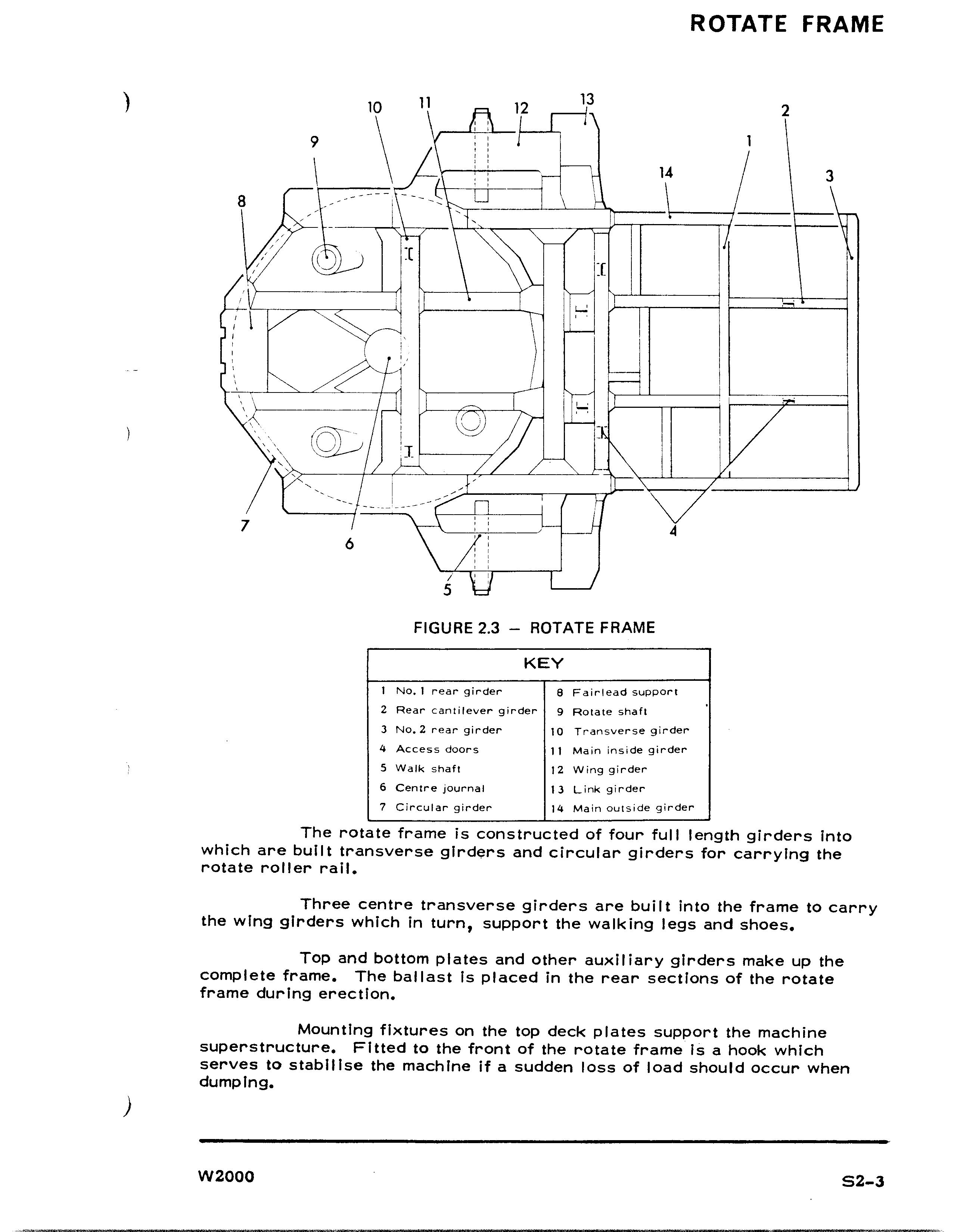
4 Access doors 11 Main inside girder
5 Walk shaft 12 Wing girder
6 Centre journal 13 Link girder
7 Circular girder 14 Main outside girder
The rotate frame is constructed of four full length girders into which are built transverse girders and circular girders for carrying the rotate roller rail.
Three centre transverse girders are bull t into the frame to carry the wing girders which in turn, support the walking legs and shoes.
Top and bottom plates and other auxiliary girders make up the complete frame. The ballast Is placed in the rear sections of the rotate frame during erection.
Mounting fixtures on the top deck plates support the machine superstructure. Fitted to the front of the rotate frame Is a hook which serves to stabilise the machine if a sudden loss of load should occur when dumping.
• Thank you very much for reading the preview of the manual.
• You can download the complete manual from: www.heydownloads.com by clicking the link below
• Please note: If there is no response to CLICKING the link, please download this PDF first and then click on it.