
Technical Manual
• Thank you very much for reading the preview of the manual.
• You can download the complete manual from: www.heydownloads.com by clicking the link below
• Please note: If there is no response to CLICKING the link, please download this PDF first and then click on it.

OPERATION AND MAINTENANCE
INSTRUCTION MANUAL
NO. 1004
MARION 7800
WALKING DRAG LINE
Manufactured By
MARION POWER SHOVEL CO.
MARION, OHIO, U.S. A.
SECTION I
ERECTING INSTRUCTIONS
to cIIod _ on t.Yt1 9I'0Il00,
In cow 9'Ound IS not Ieotl, dead ""'" will hoy. to b4t plcclll , turlhe, ''''''' indic.1Id to pro.1de boom o"'o,ance

Doitod men ""'" 3' wide • 6' 10 8' dtt!> • 'ii Doitod 109 20" olio .• 7'10 II' kln9 Of" lid.
R.R. I•• , Dead mon c<lbk> 1-112" clio, • 1r:J 10"'3 IIcIuIIIM 0,""00 IoQ and 'o.!HId,
Loe<r'IM .f "10 ton, 110'-0' boOII\ tid< !Or ....:lIon of Tyl>' 1Il00 WaIIoItr
ERECTING INSTRUCTIONS FOR MARION 7800
These instructions have been prepared to aid in erecting a MARION 7800 WLE Walking Dragline; a guide for operator, the groundman, and the oiler in their operatioJil, and lubrication. The engineering drawings which ac:compa!ny the machine give the exact location of all parts. all necessary dimensions, etc. It is very important that extreme care be taken in assembly because improper erection may cause unnecessary wear and faulty operation of the machine.
When the machine is shipped from the factory. the partsarematchmarked throughout. Care should be taken to follow these match marks when the machine is assembled.
All finished surfaces and bearings are protected against corrosion and should be thoroughly cleaned just before assembly. When assembling. all bearings should be lubricated. Ball and roller bearings are to be filled only 1/2 full of the proper Also lubricate all gears and put the proper oil in gear cases up to the correct level before the machme is run. All air and electrical equipment, bearings and finished surfaces should be protected from the weather until the machine is fully assembled.
Select a level assembling area adjacent to the uDloading point approximately 300' x 300' preferably made up of solid mateTial and with good drainage. It may be advisable to place gravel or cinders in the immediate erection area.
It is important that the derrick be placed so that the greate st loads can be lifted without interfering with the erection of the machine. The recommended position of this derrick is mdicated on drawlng CR-4564. If the ground is not level, place the dead men out further than the 425' indicated for boom clearance.
REQUIRED MATERIAL
Following is a list of materials required to aid in the erection of the machine. They are to be furnished by the purchaser.
24 2 x 10 or 12" Planks x 20' long
12 2 x 10 or 12" Planks 10' to 12' long
90 2 x 10 or 12" Planks 14' to 16 1 long
200 2 x 4 - 16 1 to 18 1 long
60 2x 4 -8 1 to 10' long
1000 Standard railroad ties
1000 Miscellaneous flat blocking 2" x 6" x 12"
8 Dead men logs for anchoring derrick guys. 20 tl diam. x 7' or 8 1 long. or can use 32 standard railroad ties
TOOLS AND EQUIPMENT
It is recommended that a small tool room be erected at the erection site for the protection of the tools, dri;lwings. etc No. 1004/1
One electric welding machine is required to be used throughout the erecting period. Also, four electric welding machines are recommended for use in the tub assembly.
Consult Marion Power Shovel Company regarding derricks, tools and other equipment for use when erecting the machine.
It is recommended that the following procedure be used in erecting the machine.

1. Assemble sections of lower frame or tub. (Refer to erecting prints for a detailed "Field Assembly Procedure lt or consult Marion Power Shovel Co. engineers).
a. Tub consists of three center sections and four outer sections. First, place center sections and bolt together.
b. Install center journal.
c. Place outer sections, bolt to center section, level entire tub and then weld.
Caution: Remove all manhole covers during assembly to allow weld fumes to escape.
d. Tub should be rechecked for level and circle rail bearing surfaces checked for levelness with transit.
2. Install main swing gear segments, accurately tram, bolt down and weld, according to assembly instructions.
3. Install lower circle rail, accurately tram, and bolt to tub.
4. As semble roller circle, making certain that the small diameter of the roller is to the inside of the circle.
5. Install upper circle rails on the roller circle in such a position that boom end of upper frame will be pointed toward derrick. (See CR-4564)
6. Burn off lifting lugs and grind smooth.
7. Assemble sections of rotating frame.
is well greased and shear blocks welded in place before placing center section over it. BI116002
ERECTING PROCEDURE
a. In assembling the upper frame, the electrician should install the conduit, wiring and electrical equipment simultaneously with erectors to avoid being blocked out.
1004/1 ( ( )
c. Place cribbing under both front and rear of center section and- front section so that there is approximately 3'-01t between the tub and the upper frame. This will allow room to work on the underside of the upper frame. Be sure center section is level.
d. Assemble main swing shafts and swing gear cases, on front section of upper frame. (When upper frame is lowered onto tub, the pinions on main swing shafts must be meshed with main swing rack on the tub. This is best accomplished by turning main gear in gear cases).
e. Place right and left side sections in position, align and bolt for riveting.
f. Place lower superstructure in position. This will not include any of the cross members for they will interfere with lowering the machinery from above. Align all members and bolt for riveting.
g. Install right and left wing sections and bolt for riveting.
h. Install rear section and bolt for riveting.
1. Ream where necessary and rivet rotating frame complete.
j. Place jacks under frame, remove cribbing and call'efully lower the frame onto the roller circle on tub. Fasten upper rails to rotating frame.
8. Build secure crib under rear of rotating frame to support ballast and machinery.
9. L. P. 255 (Page 10) shows method of distributing the ballast so that the machine will be properly balanced when in operation. During this operation care should be taken so as not to damage the electrical conduit.
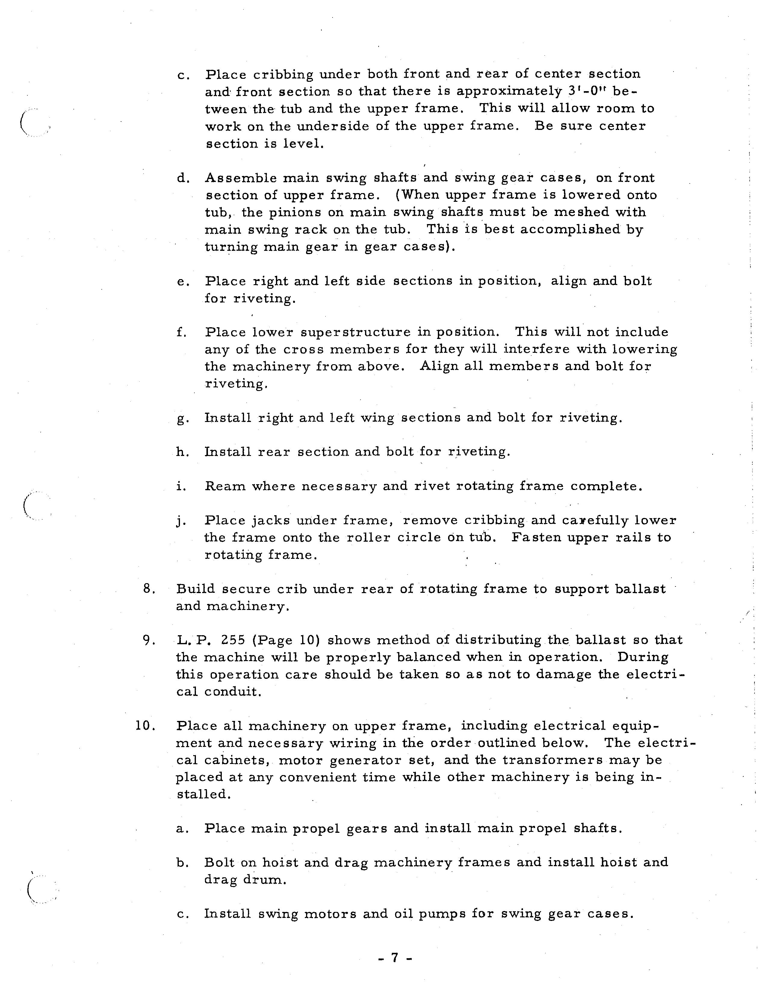
10. Place all machinery on upper frame, including electrical equipment and necessary wiring in the order outlined below. The electrical cabinets, motor generator set, and the transformers may be placed at any convenient time while other machinery is being installed.
a. Place main propel gears and install main propel shafts.
b. Bolt on hoist and drag machinery frames and install hoist and drag drum.
c. Install swing motors and oil pumps for swing gear cases.
d. Install main drive cases, 2nd intermediate extension shaft, hoist and drag motors.
e. Install air compressor.
11. Install lower cross beams of superstructure. Bolt and rivet. (Be sure crane trolley girders are installed before cross beams are placed)
12. Install fairlead.
13. Install walking towers and stub shafts. Align, bolt and rivet. It is particularly important that the matchmarks be followed exactly during this installation.
14. Assemble boom complete. This can be a simultaneous operation with other phases of erection. (See 22).
15. Install front and rear of house.
16. Place roof trusses and eave angles.
17. Place operator's cab.
18. Assemble upper structure.
19. Install gantry cap. Place boom hoist machinery on gantry.
20. Install front and rear gantry bracing and all other connecting beams, ream, bolt and rivet. Gantry braces are assembled and riveted before placing and welding on the upper structure. Weld stiff legs, top and bottom first, and then insert the assembled and riveted braces,
No t e : Before roof of house is installed, keep machinery and electrical equipment well covered.
21. Install and weld house roof.
22. Connect boom to rotating frame. (Boom may be connected as a complete unit or foot section may be assembled first on upper frame and the rest of the boom built from foot section.
23. Reeve cables. Reeve boom hoist cables first. Reeving is more easily accomplished by welding or brazing 7/ 8 u x 300' (or longer) cable to one end of the boom hoist cable. After threading this smaller cable
by hand as far as it will go, pull boom cable through with the 7/8" cable. After connecting boom hoist cable to the boom hoist, pull up taut (with boom still on ground) and reeve boom safety cables in same manner as boom hoist cables. See section for cable reeving diagrams.
24. Install air piping.
25. Complete house.
26. Install walking cranks and walking shoes.
27. Raise boom and remove all cribbing.

28. Make all necessary adjustments and completely recheck the machine for any loose bolts, nuts, cotters or errors in assembly. Remove all tools and equipment. Check all moving parts for obstructions which may cause damage.
29. Install the proper type and amount of oil in all gear cases and completely lubricate the machine with type of lubricant recommended in the lubrication section.
Caution: Machine is shipped less fluid lubricant in gear cases. Make sure that they are filled.
After painting is completed, the Il,lachine is ready {or testing and making electrical settings.
NOTE - Fill pockets indicated on table any additional ballast required to be in pockets 0, C" E.
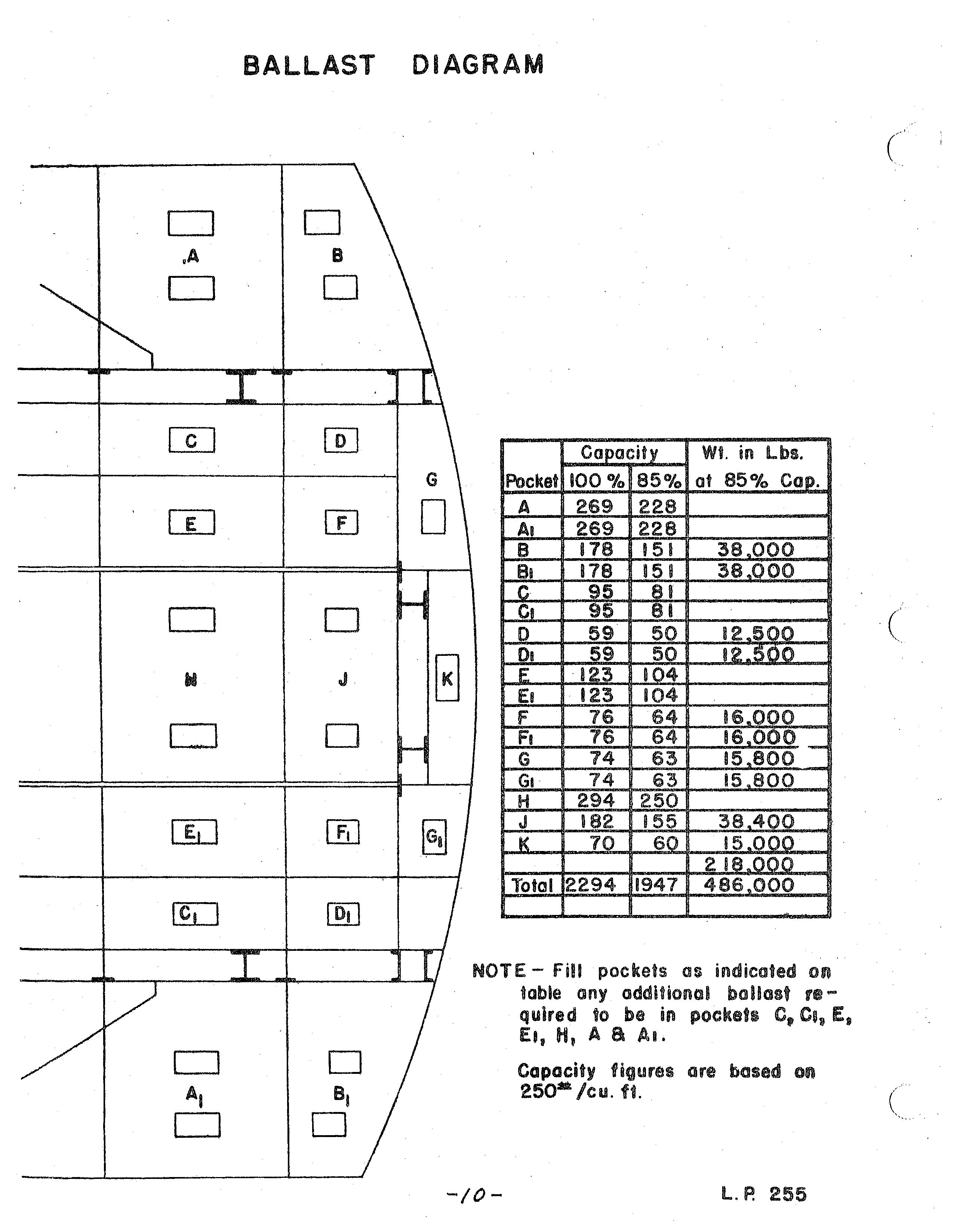
a AI.
Capacity figures are based on 250-/cu. ft.
SECTION II ADJ USTMENTS

