
Technical Manual
• Thank you very much for reading the preview of the manual.
• You can download the complete manual from: www.heydownloads.com by clicking the link below
• Please note: If there is no response to CLICKING the link, please download this PDF first and then click on it.

OPERA TION AND MAINTENANCE

INSTRUCTION MANUAL
MARlON 7400 ELECTRIC
WALKING DRAGLINE
No. 1017
Manufactured by
MARION POWER SHOVEL COMPANY
MARlON. OIDO, U. s. A.

SECTION I

ERECTION INSTRUCTIONS
MARION 7400 ELECTRIC
WALKING DRAG LINE
GENERAL
Th•• e inatructiona have been prepared to aid in erecting a Marion 7400 Electric Walking Dr"gline, guide lor the operator, the groundman, and the oller in their operatioD, maintenance and lubrication. The engineering drawins. whicla ( accompany the machine, give the exact location of all part., all nec ry dim.enaiona, etc. It b Tery important that Ilxtreme eare bo taken in ... eembly becav.ae improper erection may caum.e unneeelluJ.a.ry wear and faulty operation of the machine.
When the machine is shipped from the factory, the part. are match marked throughout. Care ahould be taken to follow thellle match marks when the machine baa.embled.
All finbhed aurfaces and bearingl are protected againet corr0810n and ehauld be thoroughly cleaned just before aa membir. When astBembUng. all bearmgs should. be lubricated. Ball and roller bearings are to be filled only Ill. full of the proper ,reaae. Abo lubricate all gears and put the proper oil in gear ca..e8 up to the correct leyel before the rna.chlne is run. All air and electrical equipment, bearings and finished lIurfacea should be protected from the weather until the machine is fully a.sembled. .
Select a level assembling area adjacent to the unloading point approxhnately 300' x 300 ' preferably made up of solid material and with good drainage. It may be adYillable to place gravel or cinders in the bnmediate erection area.
It 111 important that the derrick be placed 80 that the greatest loads can be lUted without illtederring with the erection of the machine. The recommended poai .. tion of this derrick ill indieated on drawing CR-4585. If the ground ill not level, place the dead men out further than the 300' indicated for boom clearallceo
M..A TERIAL REQUIRED '
(For Domestic Shipment)
Following is a Ult of materials required to aid in the erection of the machine. They are to be furnillhed by th.e purchaser. .
200 - Standard rails
48 - Z x 10 or 12/1 plank 12 to 14 .feet long
100 - 2 x. 4: - 16 to 20 feet long
8 - Dead men logs 20" dia. x 7' to 8 f long or can uille 32 standa.rd railroad ties for anchoring derrick guys.
1 - 310 cubic foot air compressor
1 - Electric welding machine
2 - 2.5 to 30 ton low lift jacks
2 - 15 ton track jack.
1 .. 15 ton chain. hoht
MA TERrAL REQUIRED
(For Export Shipment)
The following iG in addition to the above.
1017/1
.
1 - 14" Stilson wrench
2 - 24" Stillion wrenche.
1 - 48" Stilson wrench
1 - 12" Monkey wrench
8 - 5/8" construction wrenches
12 - 3/4" conlBtruction wrenches
12. - 7/8" construction wrencheli
4: - 1" construction wrenches
6 - 1-1/4" aingleendwrenches.
3 - 3/4" socket wrenches'
4: - 7/8 11 socket wrenchetlil
6 - 1" socket wrenchelilJ
4: - 1-1/8" socket wrenches
4: - 1-1/4" 1I0e ket wrenche ..
2. - 1-1/2'· socket wrenches
2 - C Plate clamp III
1 - Set stock and Dies for threa.ding pipe up to and including 3/4"
1 - Set stock a.ndDies for threa.ding pipe I" up to and including 2"
Z ., 0 to 3/4 Positive plate clamps
2 -6 lb. sledge hammer AI
1 - 8 lb. sledge hammer
1 - 12 lb. sledge hammer
2. - 2. lb. hand hammer"
2. - Fla.t fileB
1 - Half round file
6 - 12" Mill file.
3 - Gouges
3 - Gold chisels
6 - Pinch bar s
2 - 1/2 11 chain lor_on leng hook each end
2. - 3/4" chain lSt_Ou long hook each end
2. - 1't cable slings consisting of }It x 38' _0" cables. 1 link, 2 hooks, 3·2 cable clamp and 10 cable thimble 8 each
1 - Burning torch including gouges, 100 feet of hOBe, 3 tips and 3 cutting tips
.2 • Adaptors for acetylene gas tank
6 - Hose connectorllll with clamps for acetylene gall hose
2 - 3/4 Rope double gate block (for snatch block)
2 - 3/4 Rope double blocks (for snatch block)
2 - 3/4 X 150'-0" Rope
2. 3/4 X 75'-0" Rope for tag line
1 - Portable pipe vice
1 - 2'-0" Steel carpenter square
1 - Cross cut saw
6 - 7/16" Barrel drift pin.
6 - 9/16" Barrel drift pins
6 • 5/8 t1 Barrel drift piWl 24 - 25/32" Barrel drift pins
24 - 3/4" Barrel drift pinlll 18 - 7/8" Barrel drift pin.
6 - 111 Barrel drift pin.
6 - 1-1/8" Barrel drift pins
12 - 1-1 /4" Barrel drift pins
6 - 1-1/2 II Barrel drift pins
24 - 13/16" Barrel drift pins
12 - 15/16" Barrel drift pius
1 - 3/4" U. S. Std. Ta.per Tap
1 - 7/8" U. S. Std. Ta.per Tap
I - 1" U. S. Std. Taper Ta.p
1 - 1-1/4" U. S. Std. Ta.per Tap
1 - 1-1/2" U. S. Std. Taper Tap
AIR TOOLS
1 - Corner air machine with #4 Morse Chuck
1 - No. 3 air machine with #3 M.orse Chuck
1 - No. 4 air machine with 113 Morse Chuck
1 - Small one man air drill
1 - Air surface grinder
2 - Stones for above surface grinder
2 - 6" Air buckers
4 - 12" Air buckers
2 - ISO Air ha.mmers
2 - Chipping hammers
2 - *90 Air hammers
1 - ,60 Air hammer
1 - #46 Portable air grinding machine
6 - Carborundum Wheels Sit Dia. (to fit above machine)
1 - Oil burning rivet forge
2 - 2 lb. hand hammers
1 - Old man to back up 1-1/4 11 drill
6 - Flat chisels for air gun
4 - Gouges for air gun
1 - Chisel bar 3' -0" long
8 - 5/8" backing out punches (without handles)
8 - 3/4" backing out punches (without handles)
12 - 7/8" backing out punches (without handles)
6 - Handles for backing out punches
2 - Side cuts with handle s
2 - Cold cuts with handles
2 - HeaUngtongs 2' -6" long
2 - Pick up tongs 1'-6" long
IS - Rivet set clips
1 - Extension 2'-0" long with No. 3 Morse Chuck (for air machine)
5 - 5/8 button head rivet sets
6 - 3/4 button head rivet sets
6 - 7/8 button head rivet seta
6 - 1 button head rivet seta
2 - 5/8" button head rivet seta (to fit .hort bucker)
2 - 3/4" button head rivet seta (to fit short bucker)
2 - 7/8" button head rivet sets (to fit short bucker)
AIR TOOLS (Cont'd.)
2 - 1" button head rivet sets (to fit short bucker)
1 - Taper rivet set
1 - 7/8 11 rivet set to fit air bucket (to be 10" under shoulder)
2 - 3/4" (tush rivet sets
1 - Sleeve UlOO for taper shank drill #2 to ##3
2 - Taper shank sleeves #3 to ##4
6 - 3/4 jack seta
6 - 7/8 jack sets

6 - length 3/4" air hose 50 feet long
6 - length 1/2" air hose 50 feet long
1 - Lightening hose clamping tool
6 .:. 3/4 never slip hose clamps
6 - 1/2 never slip hose clamps
6 - 9/32 Drill stra.ight shank
6 -13/32 Drill 63 Morse taper shank
6 - 17/32 Drill #3 Morse taper shank
2 - 21/32 Drill 13 Morse taper shank
2 - 25/32 Drill #3 Morse taper shank
4 - 29/32 Drill #3 Morse taper shank
2 - 1-1/32 Drill #3 Morse taper shank
2 - 1-9/32 Drill #3 Morse taper shank
1 - 17/32 Bridge Reamer f/3 Morse taper shank
2 - 21/32 Bridge Reamer #3 Morse taper shank
4 - 25/32 Bridge Reamer #3 Morse taper shank
4 - 29/32 Bridge Reamer #3 Morse taper shank
3 - 1-1/8 Bridge Reamer #3 Morse taper shank 3 - 1-1/4 Bridge Reamer #3 Morse taper shank
- 1-1/32 Bridge Reamer 63 Morse taper shank
- Bridge Reamer #3 Morse taper shank 1 - 1-1/4 1400 chucking reamer 2 - 1-1/4 Rose reamer #3 Morse taper shank
- 1-1/2 Dowel pin reamer 1 - 3/4" Drill 63 Morse taper shank
1 - I" Rose Reamer #3 Morse taper shank
4 - 15/16 11 Bridge-Reamer #3 Morse taper shank 8 -
Bridge Reamer #3 Morse taper shank
1500 - 7/8" Cut washers 100 - 1" Cut washers
50 - 1-1/414 Cut washers
Z - 1-1/2" Globe valves
30 - 1/4 x 4: Nipples
30 - 3/8 x 4 Nipples
ZO - I/Z x 3 Nipples
40 - 1/2 x 4 Nipples
. 6 - 1/2 x 6 Nipples
12 - 3/8" Close Nipples
2 - 1-1/2" Close Nipples
20 - 3/4 x 4 Nipples
1 - 1-1/2" Union Elbow
Z - 1-1 /2" Union
6 - 1 / 4" Elbows
2 - 1-1/2" Elbows
6 -1 / Zit Elbows
2 - 1-1/2 x 6 Nipples
50 - 1 /2 to 3/8 Bushing
4 - 2 to 1-1/Z Reducing Bush
4 - 1-1/2 Coupling

40 - 1 / Z to 3/4 Reducing Coupling
40 - 1/2" CoupUng
15 - 3/4 11 Coupling
1 - 1-1/2 x 1-1/2 x l/Z" Tee
24 -1 / Z to 3/8 Reducing Coupling
100 - Feet l-l/Z" Pipe
1 - Manifold 4" pipe 4'-0'· long
2 - 4" Pipe Cap
19 -1 /2 11 Globe Valve
1 - 3/8" Pipe Plug
2 - 1 / 4 tf Globe Valve
24 - 3/8 to 1/4 Reducing Valve
12 - 3/4 to 1/2 Reducing Bushings
12 - Feet H2 Annealed Wire
ELECTRICAL TOOLS
2 - 4'· Screw Drivers
2 - 8" Screw Driver s
2 - 8" Pliers (side cutting)
1 - 6" Long Nosed Pliers
Z - 10" Gas Pliers
1 - 8" Mill File
1 -1 Zit Mill File
1 - 12" Double Cut File
1 - 12 Half Round File
1 - 8" Round File
5 - File Handles
ELECTRICAL TOOLS (CAnt'd. )
1 - 6" Crescent Single End Wrench
1 - IOIt Creficent Single End Wrench
1 - 1/4 to 3/4: Pipe Bendel"
1 - 5/16 X 3/8 11 Open End Wrench
1 - 7/16 x 1/2 Open End Wrench
1 - liZ x 5/8 Open End Wrench
1 - 3/4 ::It 7/8 Open End Wrench
1 - 7/8 x 1 End Wrench
1 - 1011 Stihon Wrench
1 - 12" M.onkey Wrench
Z. - 18" Pipe Wrench
Z. - Cold Chisehi
Z -
1 - Center Punch
1 - 1-1/2 lb. Hancl. Hammer
1 - 3/16 Straight Shank Drill
1 - 1/4" StrfJUlht ShAnk Drill
1 - 11 Z" Straight Shank Drill
1 - 3/B" Sqrutre Slumk Wood Bit
1 - Standard Brace
1 - 10" HllCk Saw Frame
48 - Hack SOil.W Bla.&el!!
1 - #Z Soldering lrem
1 - 6'· Melting Pot
1 - 4" Pouring udle
1 - Set Steel Letters
1 - Set 3/16" Steel Figure!!!
Z - Zit Paint lEh'uSiheso
1 - Ga.soline Furnace
1 - 1 Quart Blow Torch
1 - Z5000 OHM Ma{f.neh
1 - #Z Pipe Vi6e
1 - 75 Foet Fhh Tape
100 - Feet 1/2 Rope
100 - Feet 5/16" Tiller Rope
Z - I/Z Deu'hle :Block
1 - Steel Grip for 1/ Z Wire
1 - Set Pipe DieD 1/2 to 2 10
8 - Copper Termi.nalll 000 CM)
8 - Copper Term..iruUs 000 eM)
12 - Copper Termin&h (3/0)

TOOLS AND EQUIPMENT
It ia recommended tha.t !ilmalltool room be erected a.t the erection .ite for the protection of the wl!Jlb. drawUtlD. etc.
One electric welding machine hi required to be used throughout the erection period.
Coruault Marlon Pewer Skavel Cempam.y relardin, derrick., tooh! lUl6. other equipment for use wken erectiJig tlte machlne.
LOCATION OF DERRICK FOR ERECTION OF TYPE 7400
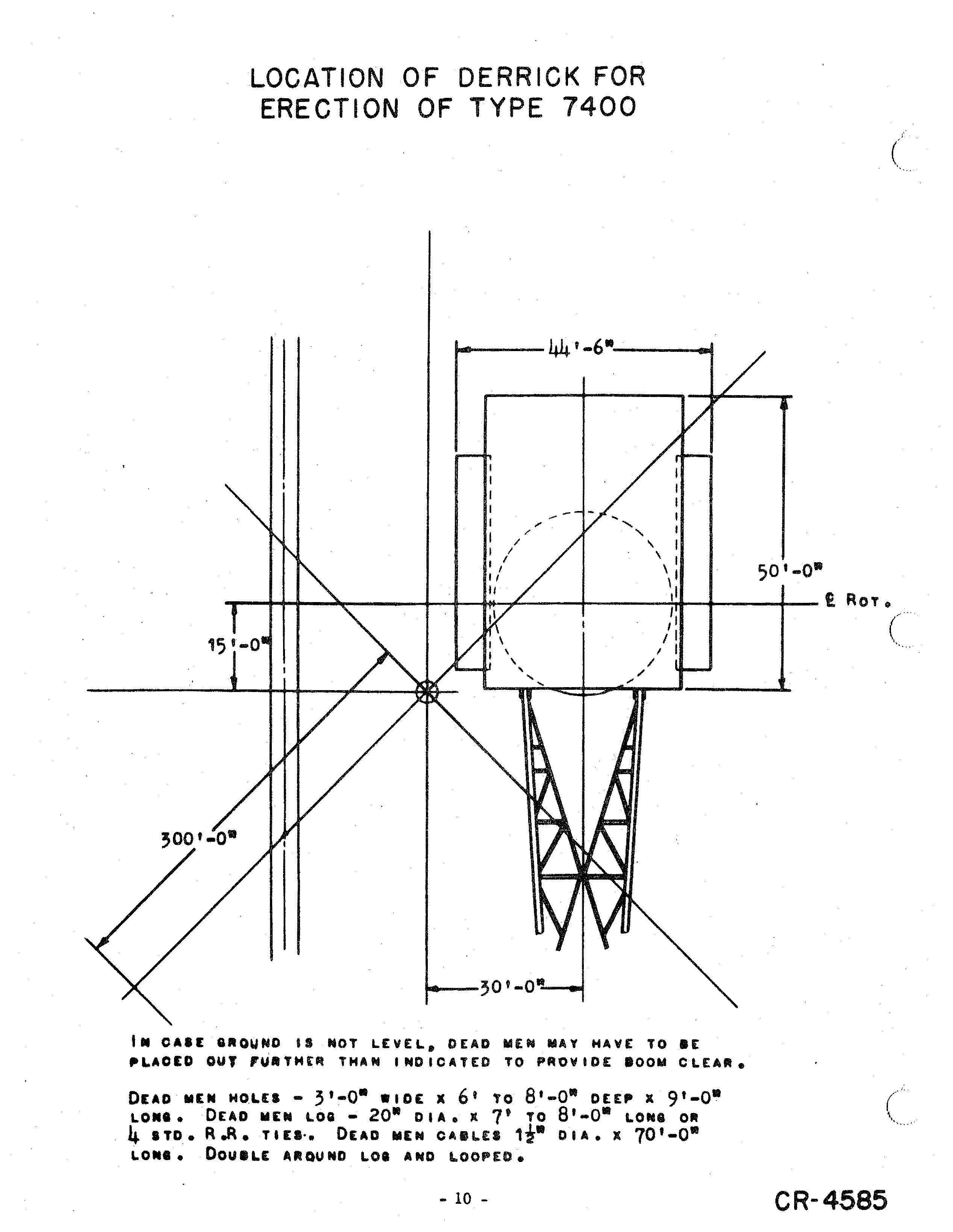
IN OAI' aROUND II NOT lEVEL. DEAD MEN MAY HAVE TO DE OUT ,U.THtR THAN INDICATED TO PROVIDE DOOM ClEAR.
DEAD MEN HOLES - 3'·0· -IDE X 6' TO 8'-0· DEEP X 9'·0LONI. DEAD MEN LOG - 20· CIA. K 7' TO 8'-0· LONe OR 4. ITO.• R.A. TUI-. DEAD MEN CA8LES 1",- DIA. X 70'-0· LONI. DOUILE AROUND LOI AND LOOPED.
ERECTION OF MACHINE
It i. recommended that the following procedure be ufBed in erec:tinll ilia mAchine.
1. ASllemble sectionll of lower frame or tub.
&. Build a. crib, prefera.bly of rallroad tie8 p approximately 30tl) high to allow for riveting and bolting underneath tub.
b. Place center section on crib.
c. Place outer secUolul and pull sections to sether t aU.p and bolt. Tub should be leveled and circle rail bearing lIu:rface checked I.1' levelness with tran.ait.
d. Rivet tub complete.
e. Bolt on wearing plates and cleat ••
1.. Remove cribbing and lower the tub to ground. (If eI'ecting the machine in the winter, it may bEl adrimable to lower the tub to & mat of clear of the cleats t under tile edgeo! the tub p to prevent freezing the tub to the ground).
Z. Install gear segmenttJ being lIureto follow matcama.rking&ll.
3. InsWI lower circle rail and bolt to tub ud:w.g wedge wtlilhers under nut"
4. 1n.IWl center journal.
5. A.semble roller circle. ma.king certain Ilmall diameter of roller ill to the inside of the circle.
6. Install upper circle rWM on the roller circle in Iruch a poeition that boom end of upper frame will be pointed toward derrick.
7. Burn off lUting lug s and grind &m..
8. A.semble llJectionll of rota.ting frame.

a.. In assembling the upper frame the electdcan liIhould install the conduit, wiring and elect:dcalequipment dmultaaeouilly with erectC1l1"a to avoid being blocked out.
b. Place center lIection of upper frame. Be .ure center journal hi well greased a.nd shear blockl weli&d in place .elora placing can"; tel' section over it.
c. Block 'UP front of center lIection on the lear liIegments to Make ea.!er installation of front girder.
d. Aa.emble main swinf,C .ha.ft an. swing geu callie on aide sectionlll of upper frame. .
e. Place right a.nd left side sections, pull each into center section. align and bolt for riveting. On placing the side sections, pinion. on main swing shalts must be meshed with main swing rack on the tub which is belilt accomplished by turning main gear in gear case.
i. Place lower superstructure and front a.nd rear girders. This will not include any of the crols members for they will interfere with lowering the machinery from above. AUgn all members and bolt for riveting,
g. In.tall right and left wing sections and bolt for riveting.
h. Inatall rear ballast box and bolt for riveting.
1. Ream where necessary and rivet rotating frame complete.
9. Build secure crib under rear of machine to support ballast and machinery.
10. Install ballast as indicated in print L. P. 287 supplied by our Engineers. Ballast should be distributed in aecordance with these instructions 80 that the machine will be properly balanced when in operation. During this operation care should be taken that electrical conduit is not Giamaged.

11. Place all machinery on upper frame including electrical equipment and necelllllIary wiring in the order outlined below. The electrical cabinet., ( motor generator set t and transformers may be placed a.t any convenient time while machinery is being installed.
a. Bolt on hoi lit a.nd drag machinery frame and install hoist and drag drum. NOTE: Slip rings should be installed before the hoht drum is placed.
b. Install swing motora and oil pumps for swing gear easel.
c. Place main propel gear and install main propel sha.£ta.
d. Install boom hoist machinery.
e. Insta.ll main drive gear case, 2nd, intermediate extension shaft, and hobt motor.
f. Install air compressor.
12. Install lower crOS8 beams of superstructure. Bolt and rivet. (Be sure crane trolley girders are installed before cross beams are placed).
13. In II tall fairlead.
14. Install walking towers and stub shafts. Align, bolt, and rivet. It is particula.rly important that ·match marks be followed exactly during this installation.
• Thank you very much for reading the preview of the manual.
• You can download the complete manual from: www.heydownloads.com by clicking the link below
• Please note: If there is no response to CLICKING the link, please download this PDF first and then click on it.