
Technical Manual
• Thank you very much for reading the preview of the manual.
• You can download the complete manual from: www.heydownloads.com by clicking the link below
• Please note: If there is no response to CLICKING the link, please download this PDF first and then click on it.

ERECTING INSTRUCTIONS
CONTENTS --------
PAR T I
Page 3
OPERATING INSTRUCrrONS
PART II
PART III
STARTING INSTRUCTIONS
PART IV
GENERAL MAINTENANCE INSTRUCTIONS
PAR T V
INSTRUCTIONS FOR MAKING ELEGrRICAL ADJUSTMENTS
(S-74OO-7 Sheets 1-13)
PART VI
Page 10
Page 22
APPENDIX
List of Tools and Equipment for Erection
Approximate Packing List for Export Recommended Lubricants Miscellaneous Instructions for Accessories Lubrication
Page 25 IN BACK OF MANUAL
ERECTING INSTRUCTIONS
For MARION TYPE 7400 DIESEL WALKING DRAGLINE
These it'lstruotion. hllve been px'epl!I.red todd in n'6Clting It. Type 7400 Diesel walking dragline. The tngs whioh aM ompany the rna.ohine (;1 ve the exact looat ion ot parts, all necessary dimensions, ete. It is very important that extreme oare be taken in beoause improper ereotion may cause unneoessary wear and faulty operation 01' the machine. The inetruotions tor the ereotion of the machine are divided into the following p;roupl8
1. Seleotion of tooh
2" Seleotiotl of site
J", Plaoing of derriok (If' not using mobile orane)
4. Ereotlon of
SELEOTION OF TOOLS
A list of recommended equipment and tools for ereotion of the maohine is inoluded as attachment' 1 in the baok of this manual. Four groups of equipment are included.
1. NecesllIary blocking
2. Meohanioal tools
3.. Air tools oil" Eleotrioal tooh
It is reoommended that a small tool room be erect'.d lilt the erection site for the proteotion of the tools. drawings, etc.
SELECTION OF SItE
In the se1eotion of & site for erection the toll_ing OGfitU... tiona should be meta
1. ,blear point of' operat ion
2. Adjaoent to railroad aldinS
3. Level area 300' x 300' preferably made up of 50114 ..terlal and with good (It, -1 be advisable to plaoe VG"fel or oinders in the immediate erection arH_)
PLACING OF DERRICK
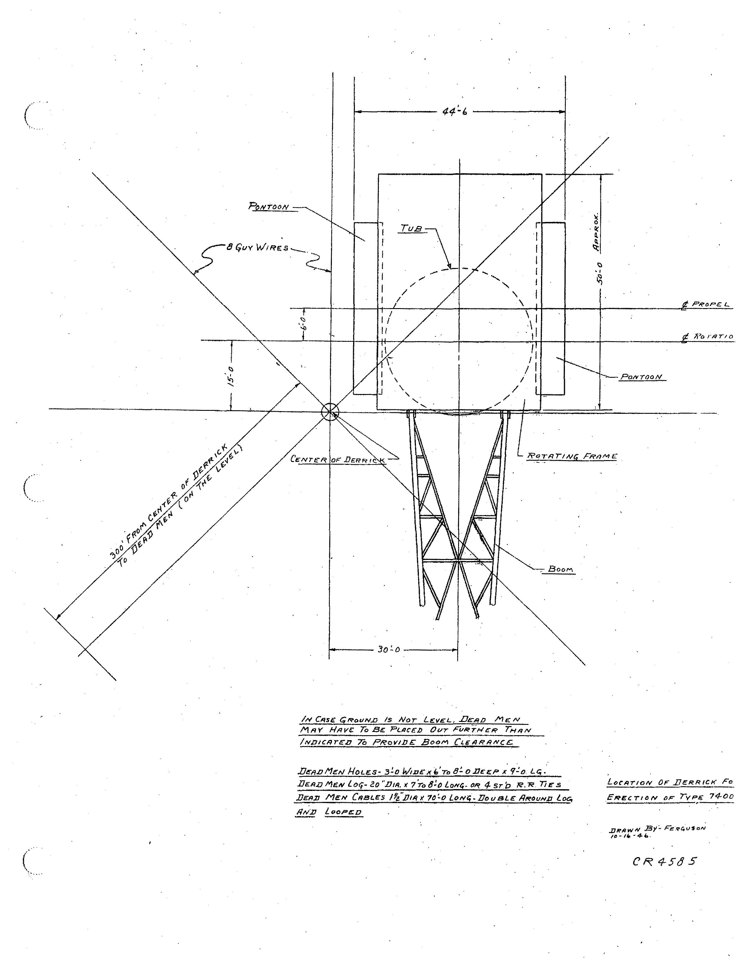
It 1s important that the derriok be placed 50 that the veat.. . est Oan be lifted without interterrint with the ereotion of the maohine\) This position of the derr.1ok has been 'indioated in Drawing No. CR4,85 "Looation or Derriok for Er.9otloz:l
.a£ :ype 7400". 'On the next. page.
IN CASE <iROUN.D IS NOT L£VEL, .De:l'/iJ MECN Mi'lV Hl'lvo: To Be: PLnCEI> Ovr FVRTi'lER THAN IND/CI'ITI!:D 70 PRev/bE: BooM LLE,qP,qIVCI!:.
/{OLI!S- 3!O W,J:lI, x ,,' To a! O.11f: I!P I; <,:!O. LC; •.
fr/EN lOli- aO ".1111/, >t: 7To l.ON". 4- ST.D R,"R. n E' S
MeN ClIsl..es 1fz.'DI19 If 7() LoN,.. O,ew aLE: Ilf'tOuND loe, /fN)] LooPl!:o
EHECTION OF riiACHlNE
The approximate breakdown of units and parts of the maohine as it will be shipped, for export only, is shown in\the "Approximate Packing List for Type 7400 Diesel Walking Dragline" whioh is included as atta.chment 2 in the back of the manual. YVnen, the,maohine is shipped from the fa.otory all pieoes are matchmaX'ked for correot assembly by small stamped numbers and paint. ·iVhen assembling the maohine all bearing surfaoes should be thoroughly cleened and lubrioated with, the oil or grease recommended for that pa.rticular bearing as indioated in "Reool11mcmdod Lubrioants for Merion Excavators and Cranes" whioh is included us ettaohment 3 in the baok of this manuel. This also applies to all external gears, gear oases, and

It is reoommended that the following prooedure be used in erectine; the mnohine.
1. Assomble lower frame or tub.
a. Build a orib, preferably of railroad ties, approximately 30 n high to allow for riveting and bolting undernea.th tub.
b. Place center seotion on crib.
c. Pluce outer sections and pull seotions together. Align and bolt. Tub should be leve18d and oirole rail bearing surface be checked for levelness with transit.
d. Iteam and rivet tub completely.
e. Bolt on wearing plates and oleats,
f. Remove oribbing and lower tub to ground., (If the machine in the winter, it may'be advisable to lower the tub to a ma.t of timber, olear of the .cleats, under the edgo of the tub, to prevent freezing the tub to the ground,)
2, Install gear segments being sure to follow matoh" markings.
3. Install lower circle rail and bolt to tub using wedge washers under nut.
4. Install Q,enter. journal.
,. Assemble roller oirole making oertain that s.mall qiQll1Star of rollel"' is to the inside of oirole •
• Thank you very much for reading the preview of the manual.
• You can download the complete manual from: www.heydownloads.com by clicking the link below
• Please note: If there is no response to CLICKING the link, please download this PDF first and then click on it.
6•. Install upper circle rails on the roller oircle in such a position that boom end of upper frame will be pointed toward derrick (as Bhown on Drawing No.
7. Burn off lifting lugs and grind smooth.
*ssemble sections of rotating frame.
a. In assembling the upper frame the electrician should installl the conduit, Wiring and electric·al equipment simultaneously with erectors to avoid being blocked out.
b. Place center section of upper frame. Be sure center journal is well greased and shear blocks welded in place before placing center section over it.
c. Block up front of center section on the gear segments to make easier installation of front girder.
d. Assemble main rotating shaft and rotating gear case on side sections of upper frame (Right and Left).
e. Place right and left side sections, pull each into center section, align and bolt for riveting. On placing the side sections, pinions on main rotating shafts must be meshed with main rotating rack on the tub which is best accomplished by turning medn gear in gear case.
f. Place I01Ner superstructure and front and rear girders. This will not include any of the cross members ror they willinterrere with lowering the machinery from above. Align all membel"R and bolt for r:5.veting.
g. Install right and left wing sections and bolt for riveting.
h. Install rear ballast 'box and bolt for riveting.
i. Ream where necessary and rivet rotating frame complete.
9. Build secure crib under· rear of machine to support ballast and machiner;r.
10. Install ballast as indicated on the blueprint' supplied with the erection prints by our Engineers. Ballast should be distributed in accordance with these instructions so that the mechine will be properly balan.ced when in operation.
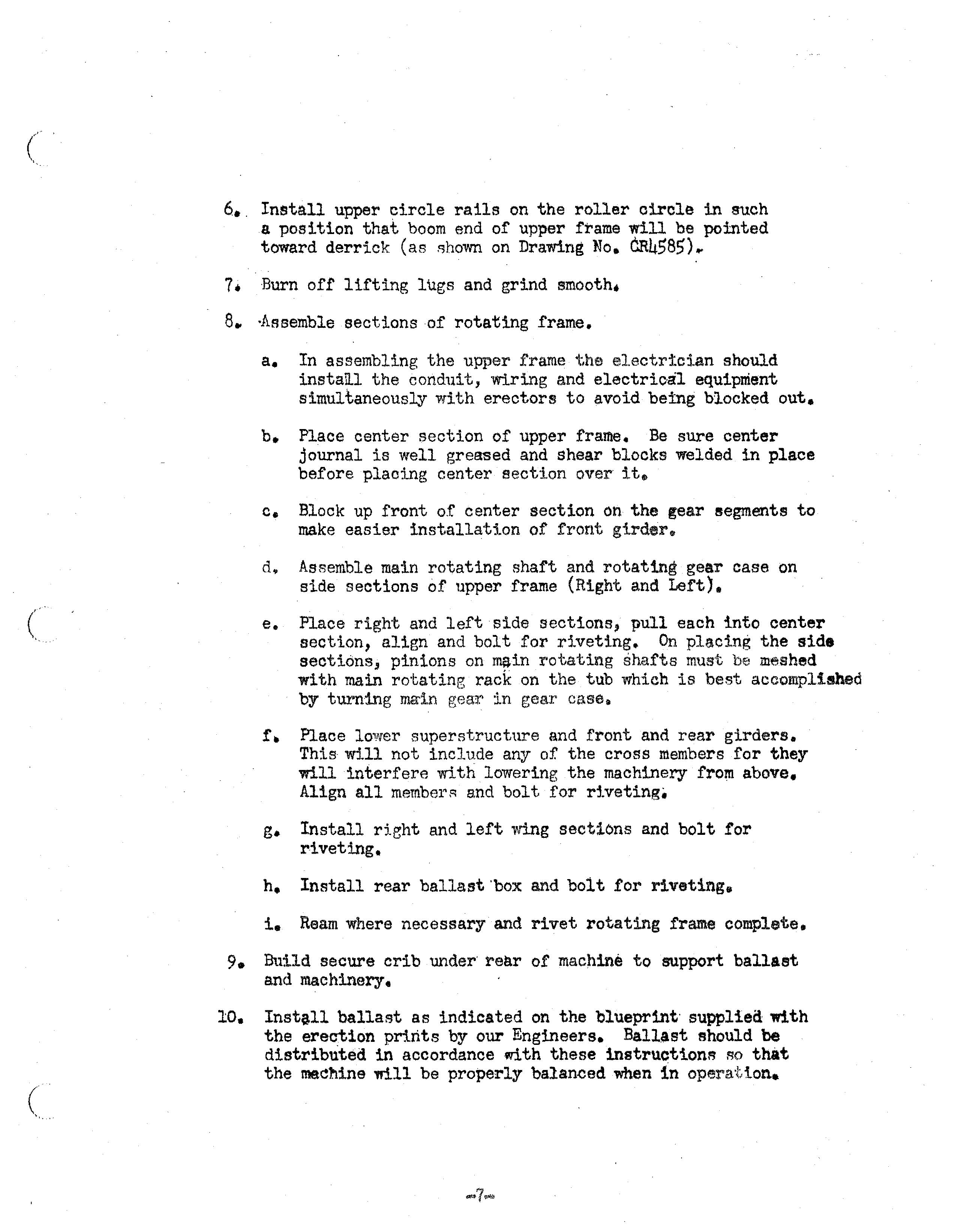
DUrt\.ng this operation care should be taken that electrical ecriduit is not
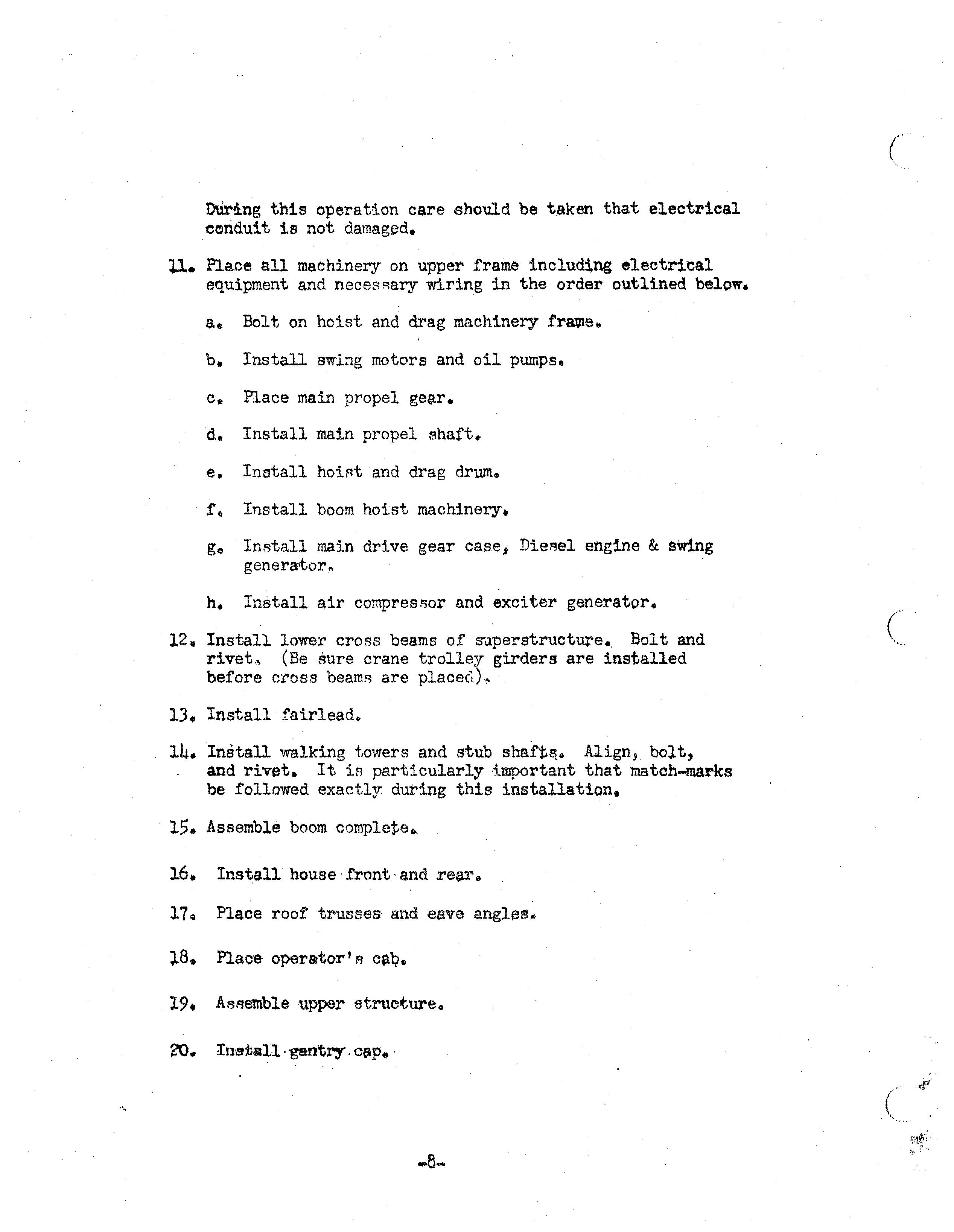
11. Place all machinery on upper frame including electrical equipment and necesRary wiring in the order outlined below.
a. Bolt on hoist and drag machinery
b. Install swIng motors and oil pumps.
o. Place main propel gear.
d. Install main propel shaft.
e. Install hoiRtand drag drum. Install boom hoist machinery.
go Install main drive gear case, engine & Swing generator!,
h. Install air and exciter generator.
12. Install lower cross beams of Bolt and (Be sure crane trolley girders are insta.lled before cross beams are
13. Install fairlead.
14. Install walking towers and stub Align, bolt, and rivet. It is particularly important that match-marks be followed exactly during this installation.
15. Assemble boom complete. Install house·front'and rear .. Place roof trusses· and eave angles.
Plaoe operatort R cfl,'Q.
19. upper structure.
21. Install front and rsar gantry and all other oonneoting beams. Ream, 'bolt and rivet. Gantry braces are assombhd·Q.nd riveted before placing and walding on the upper struoture. Weld stiff legs top and bottom first and then insert the as sembled and ri vetedbraoes_
22. Irtstal1 and weld house root,

23. Conneo J .:: boom to rotating ;f'rame, (Boom. maybe' oonneoted us .8 ooril.plete unit or foot seotion may be assembled·first on upper frame the rest of the boom built from 1'oot seotion.)
24. Reeve oables. Reeve boom hoist oables first .• Reeving is more easily aocOII'lp;Lished by welding or brazing a 7/8 11 by 300 t (Or longer) oable to one end of the boom hoist oable. After threading this smaller oable by hand as far as it will go, pull boom cable through with the 7/8" oable. After connecting boom hoist oable to the boom hoist. pull up taut (with boom still on ground) and reeve boom safety oables in same manner as boom hoist oables.
25. Install ail' piping.
26, Complete house.
27. Install walking oranks and walking shoes.
28. Cheok all moving parts for obstructions whioh maycuuse damage.
29. Raise boom and remove cribbing at rear 01' maohine,
The maohina is now ready for testing and making angine and eleotrioal settings. This prooedure is desoribedin the operating instruotions.
PART II
OPERATING INSTRUCTIONS

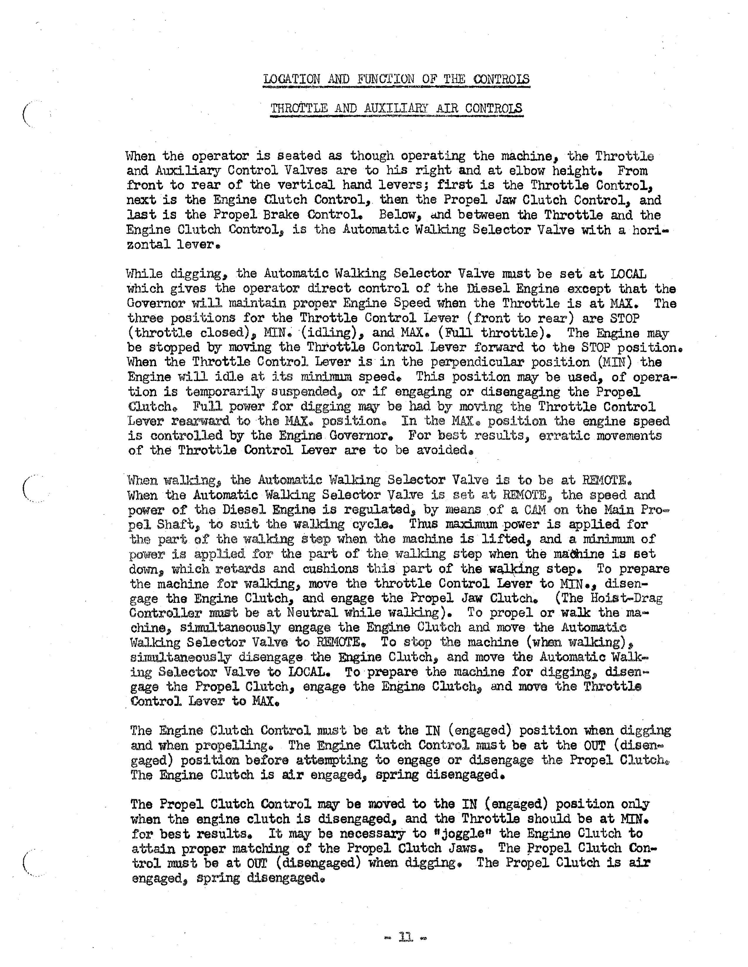
LOCATION AND FUNCTION OF THE CONTROIS
v-]hen the operator is seated as though operating the machine, the Throttle and Auxiliary Control Valves are to his right and at elbow height. From front to rear of the vertioal hand levers; first is the Throttle Control" next is the Engine Clutch Control, then the Propel Jaw Clutch Control" and last is the Propel Brake Control. Below" QJ1d between the Throttle and the Engine Clutch Control, is t/hs Automatic WaJ..ldng Selector Valve with a horizontal lever.
'V>1hile cligging,the Automatic Walking Selector Valve must be set at LOCAL which gives the operator direct control of the Diesel Engine except that the Governor w.:i.ll maintain proper Engine Speed when the Throttle is at MAX. The three posHiions for the Throttle Control Lever (front to rear) are STOP (throttle closed), '(idllng), and MAX. (Full throttle). The Engine may be stopped by moving the Throttle Control Lever forward to the STOP position. When the Throttle Control Lever is in the perpendicular position (MIN) the Engine will idle at its :m.:i..n:i.nnlm speed.. This position may be used" of operation is temporariliv suspended" or if engaging or disengaging the Propel (''lutch@ Full power for digging be had by moving the Throttle Control 'Lever rearlliT81"d to the l1AX" positione In the 11AX<II position the engine speed is controlled by the Engine GoverIlor. For best rasuJ.ts, erl"atic mo-vements of the Throttle Control Lever are to be avoided.
When the Automatic "Talking Selector Valve is to be at REt-lOTE. Wf.t.en the Automatic Wa,1ldng Seleotor Valve is set, REMOTE" the speed and power ot the Diesel Engine is regulated" by nlerulS .0£ a C1l.M on the Main Propel Shafts; to suit the walking cycle. Thus ma.ximumpower is applled for the part of the walking step when the machine is lifted" and a. rn:i.n:i.mu.nt of power is applied for the part of the walking step when the madrine is Bet down, which retards and cushions this part of the step. To prepare the machine for wa.lking, move the throttle Control Lever to MIN., disengage the Engine Clutch" and engage the Propel Jaw Clutch. (The Hoist-Drag Controller IIi.1.Ui!t be a.t Neutral while walld.ng). To propel or waJk the machine" sinmltaneousl,Y engage the Engine Clui:.ch and lIlDYEl the Automatic Walking Selector Valve to REMOTE. To stop the machine (when walking) simultaneously disengage the Engine Clutch, and move the Automatic Walking Selector VaJ.ve to LOCAL. To prepare the machine for digging", disengage the Propel Clutch" enga.ge the Engine and move the Throttle Control Lever to MAX. '
The Engine Clutch Control llll..'lSt. be at the IN (engaged) position when digging and when pl"opellingo The Engine Clutch Control mus t be at the OUT (dis en... gaged) positicm. beiore attempting to engage or disengage the Propel Olutch", The Engine Clutch is air engaged" spring disengaged.
The Propel Olutch Control Wi\Y be moVed to the IN 'engaged.) position only when the engine clutch is disengaged" and the Throttle should be at MIN. for best results. It:may be necessary to ft joggle" the Engine Clutch to attain proper matching of the Propel Clutch Jaws. The rropel Clutch Control must be at our (disengaged) when digging. The Propel Clutch is air engaged, spring disengaged.
• Thank you very much for reading the preview of the manual.
• You can download the complete manual from: www.heydownloads.com by clicking the link below
• Please note: If there is no response to CLICKING the link, please download this PDF first and then click on it.