
Technical Manual
• Thank you very much for reading the preview of the manual.
• You can download the complete manual from: www.heydownloads.com by clicking the link below
• Please note: If there is no response to CLICKING the link, please download this PDF first and then click on it.

TABLE OF CONTENTS

This m nance me ommend ments an Marion P lowed car
nual is to serve as a guide to the operators and mainte-
To all who service and operate this machine, we reccareful reading of this mat:1ual. All information, measurespecifications in this manual have been approved by the weI' Shovel Engineering Department and should be folfully.
This m nual is not to be used when ordering parts. You have been furn shed a repair parts catalogue which lists all parts by group nu bers with item and part numbers for your particular machine.
The folowing information is required when ordering parts:
1. Type
2. Serial Number
3. Group or Repair List Number
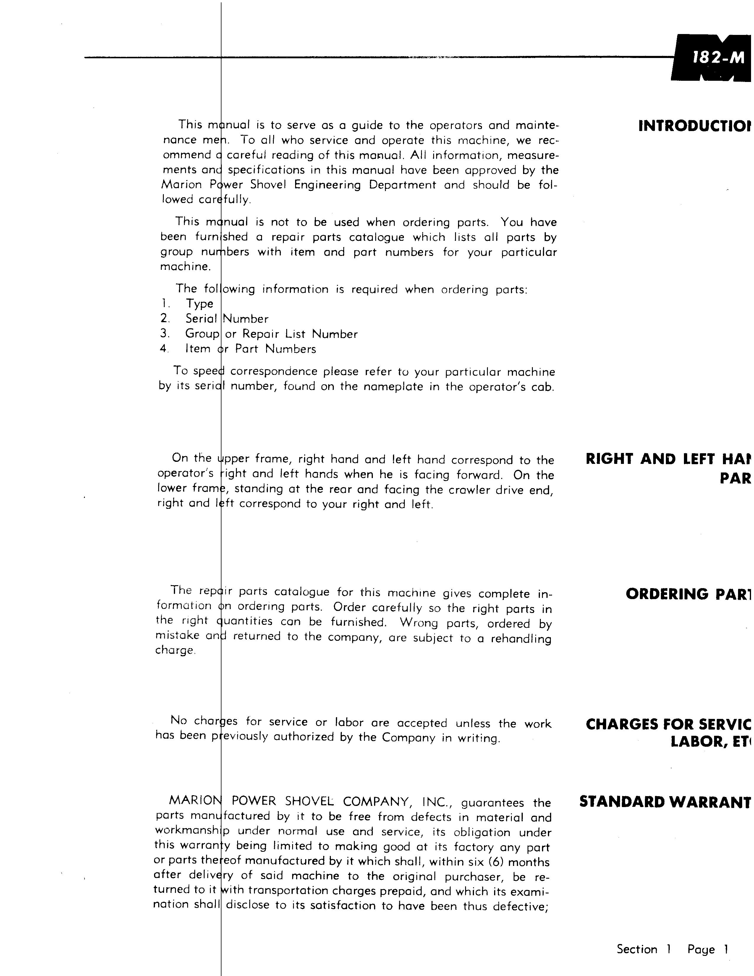
4 Item I' Part Numbers
To spee correspondence please refer to your particular machine by its seri I number, fOund on the nameplate in the operator's cab.
On the operator's lower fram right and I
pper frame, right hand and left hand correspond to the ight and left hands when he is facing forward. On the , standing at the rear and facing the crawler drive end, ft correspond to your right and left.
The rep ir parts catalogue for this machine gives complete information 1'1 ordering parts. Order carefully so the right parts in the right uantities con be furnished. Wrong parts, ordered by mistake an returned to the company, are subject to a rehandling charge No char es for service or labor are accepted unless the work has been p eviously authorized by the Company in writing.
MARIO POWER SHOVEL COMPANY, INC., guarantees the parts man factured by it to be free from defects in material and workmansh p under normal use and service, its obligation under this warran y being limited to making good at its factory any part or parts the eof manufactured by it which shall, within six (6) months after deliv ry of said machine to the original purchaser, be returned to it ith transportation charges prepaid, and which its examination shall disclose to its satisfaction to have been thus defective;
this warranty being expressly in lieu of all other warranties express or implied, and of all other obligations or liabilities on MARION POVv'ER SHOVEL COMPANY'S part.
MA .RION POWER SHOVEL COMPANY, It...Jc., sholl not be held responsible or ilobie in any event for special or consequential damages, arising frem any couse whatsoever, and Buyer agrees to indemnify and save MARION POWER SHOVEL COMPANY, INC., harmless therefrom.
MARION POWER SHOVEL COMPANY, INC., makes no guarantee or warranty .. express or implied, as to adequacy, fitness, quality. or performance of any machine, equipment, apparatus or acnot manufactured at its own factory, which are subject only to such guaranty as may be made by the respective manufach.Jrers thereof
NERAL INFORMATION
Preventive Maintenance
To Illsure that the machine is ready for operation at all times it fr1ust be Inspected systematically so problems may be corrected before they result in serious damage or failure.
We recommend the entire machine be inspected daily. If a condition is noted during inspection which would cause damage to the equipment, corrections should be made before operation is continued.
The following check list for daily visual inspection will serve as a guide for operating personnel:
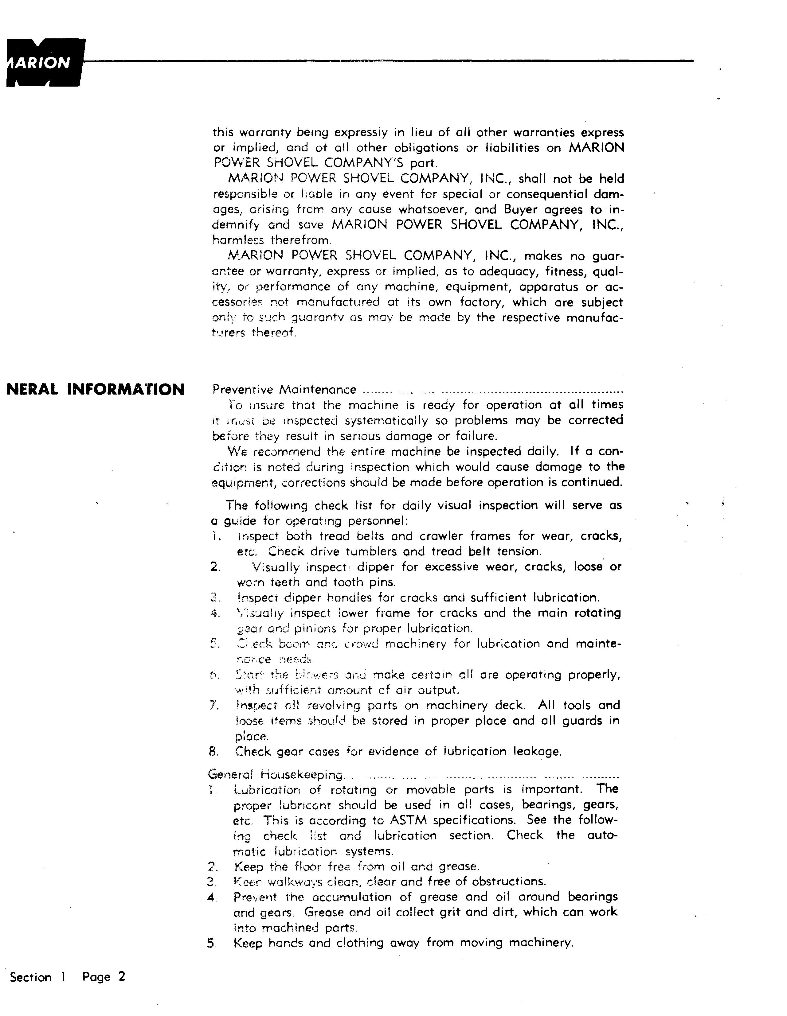
I. inspect both tread belts and crawler frames for wear, cracks, etc. Check drive tumblers and tread belt tension.
2. Visually inspect ' dipper for excessive wear, cracks, loose or worn teeth and tooth pins.
3. inspect dipper handles for cracks and sufficient lubrication.
4. \;S:.JOliy inspect lower frame for cracks and the main rotating ;;Jeer and pinions for proper lubrication.
;; ::> t:'ck boom and ((OVid machinery for lubrication and maintenotee
f.:l. ;;·:nr t;"E' ,:lnG make certain ell are operating properly, ",11th sufficierlt amoLint of air output.
i. !ngpect oil revolvit"g parts on machinery deck. All tools and loose items should be stored in proper place and all guards in place.
8. Check gear cases for evidence of lubrication leakage.
General Housekeeping... "'_"" ,.
Lubrication of rotating or movable parts is important. The proper lubricant should be used in all cases, bearings, gears, etc. This is according to ASTM specifications. See the following check list and lubrication section. Check the automatic lubrication systems.
2. Keep the floor free from oil and grease.
3. Ke",n wa1kwoys clean, clear and free of obstructions.
4 Prevent the accumulation of grease and oil around bearings and gears Grease and oil collect grit and dirt, which can work into machined parts.
5. Keep hands and clothing away from moving machinery.
6. Care and sound Judgment are the most important work rules.
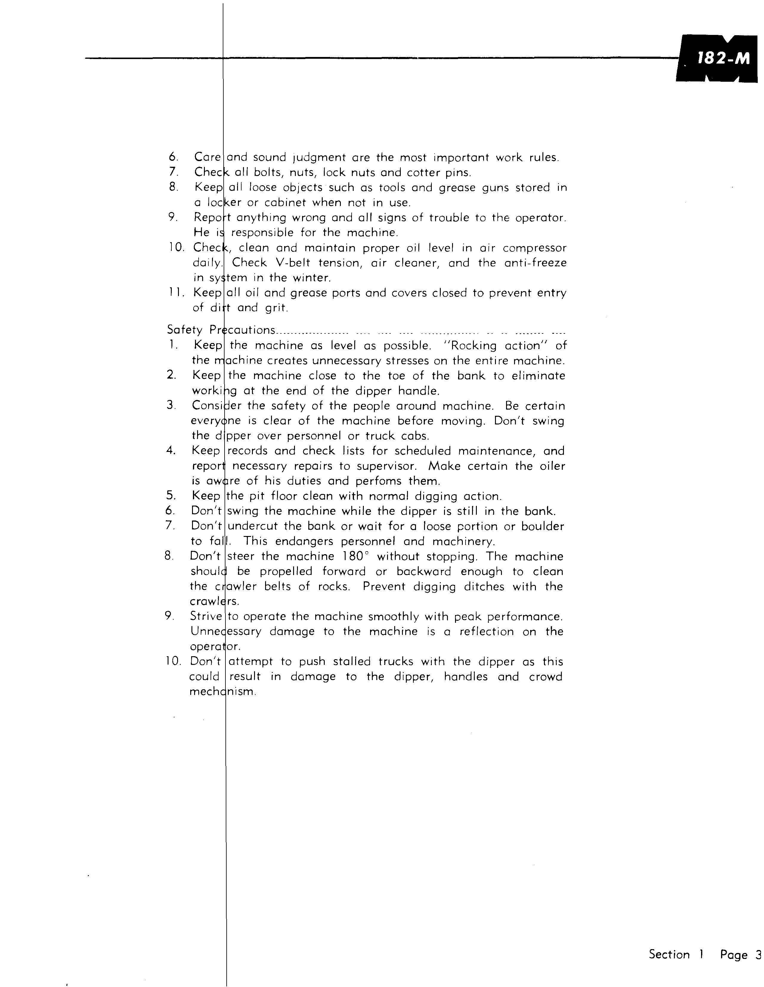
7. Chec all bolts, nuts, lock nuts and cotter pins.
8. Keep all loose objects such as tools and grease guns stored in a locker or cabinet when not in use.
9. Repo t anything wrong and all signs of trouble to the operator. He i responsible for the machine.
10. Chec , clean and maintain proper oil level in air compressor dai Iy. Check V-belt tension, air cleaner, and the anti-freeze in sy tem in the winter.
11. Keep all oil and grease ports and covers closed to prevent entry of di t and grit.
Safety Pr cautions..................... "
1. Keep the machine as level as possible. "Rocking action" of the achine creates unnecessary stresses on the entire machine.
2. Keep the machine close to the toe of the bank to eliminate worki g at the end of the dipper handle.
3. Consi er the safety of the people around machine. Be certain every ne is clear of the machine before moving. Don't swing the d pper over personnel or truck cabs.
4. Keep records and check lists for scheduled maintenance, and repor necessary repairs to supervisor. Make certain the oiler is aw re of his duties and perfoms them.
5. Keep the pit floor clean with normal digging action.
6. Don't swing the machine while the dipper is still in the bank.
7. Don't undercut the bank or wait for a loose portion or boulder to fall. This endangers personnel and machinery.
8. Don't steer the machine 180 0 without stopping. The machine shoul be propelled forward or backward enough to clean the c awler belts of rocks. Prevent digging ditches with the crawl rs.
9. Strive to operate the machine smoothly with peak performance. Unne essary damage to the machine is a reflection on the opera or.
10. Don't attempt to push stalled trucks with the dipper as this could result in damage to the dipper, handles and crowd mech

SECTION 2
BASIC r1ACHINE
rawler Tread Belt
rawler Tread Rollers
rawler Tread Belt Adjustment
ydraulic Ram Cylinder.
termediate Hoist Gear Case
oist Drum Shaft Assembly
oist Check Brake
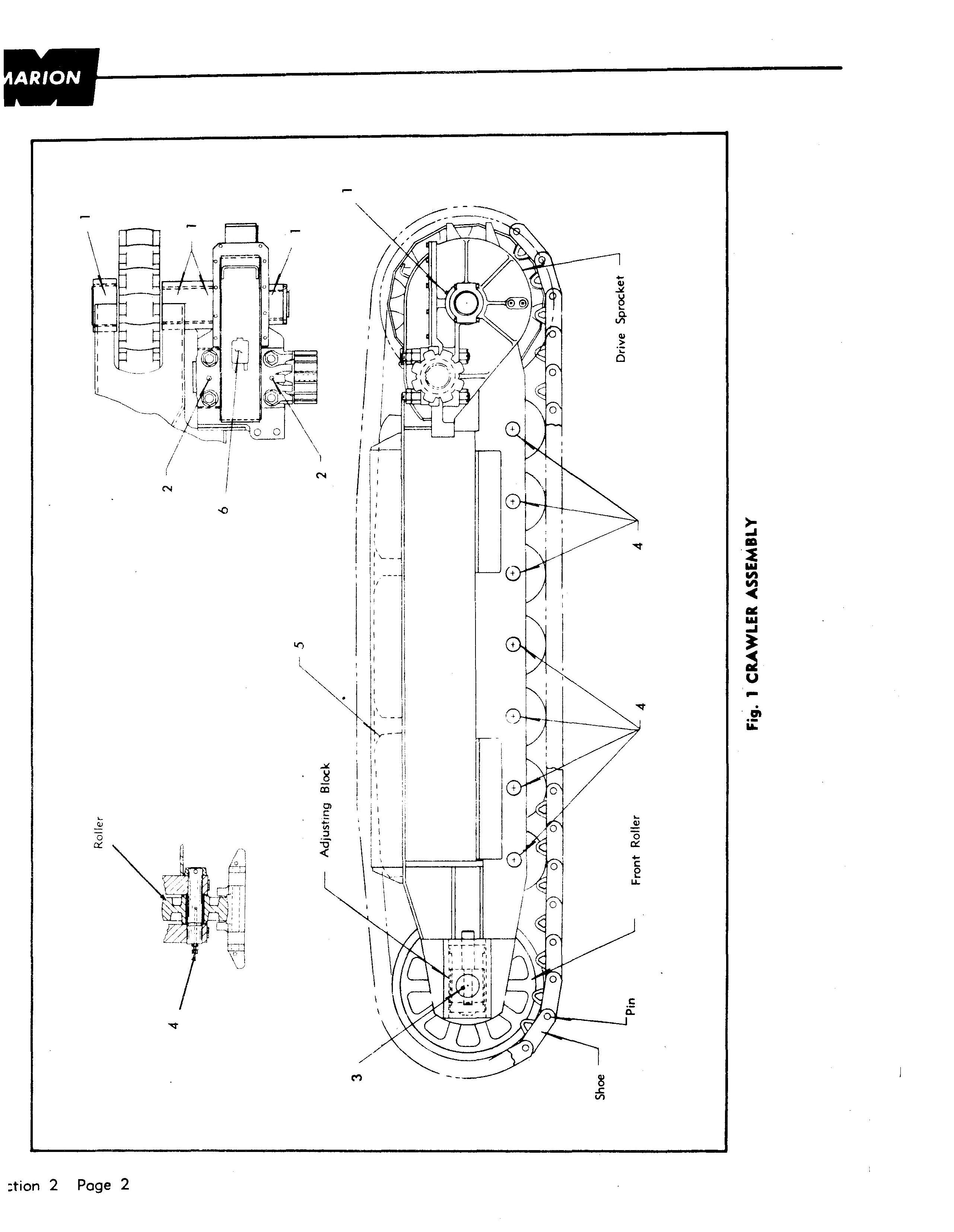
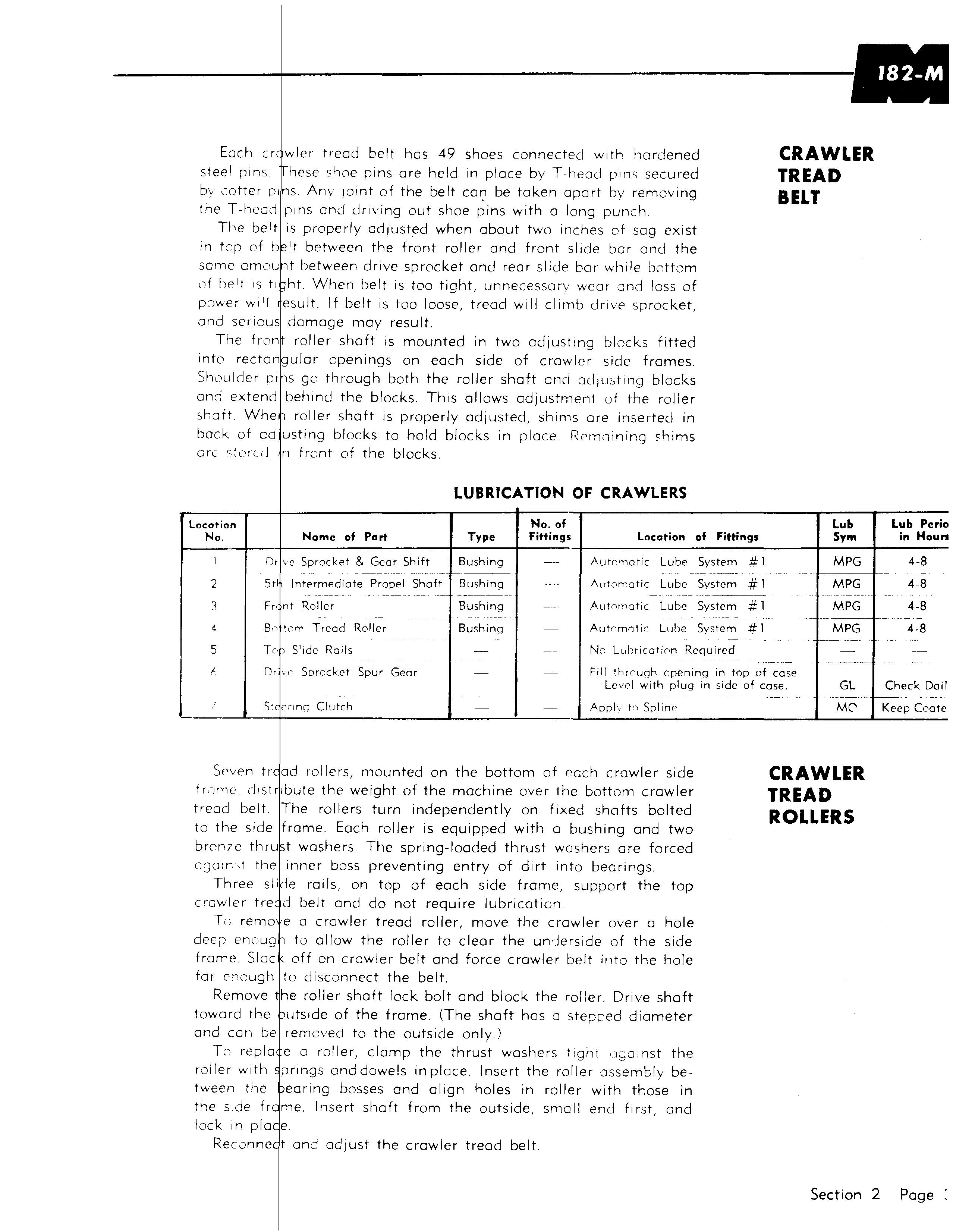
Each cr wier tread belt has 49 shoes connected with hardened steel pins hese shoe pins are held in place by Thead pins secured by cotter pins Anv JOint of the belt car: be taken aport by removing the T-hcod pins and driving out shoe pins with a long punch
The belt is properly adiusted when about two inches of sag eXist in top of b It between the front roller and front slide bar and the same amou t between drive sprocket and rear slide bar while bottom of belt IS tl ht. When belt IS too tight, unnecessary wear and loss of power Will esult If belt is too loose, tread will climb drive sprocket, and serious damage may result.
The fron roller shaft is mounted in two adJushng blocks fitted into rectan ular openings on each side of crawler side frames. Shoulder pi s go through both the roller shaft and adjusting blocks and extend behind the blocks. ThiS allows adjustment of the roller shaft. Whe roller shaft is properly adjusted, shims are inserted in bock of ad usting blocks to hold blocks in place Rrmnining shims are s t crcci nf rant of the blocks.
CRAWLER TREAD BELT Dr ve Sprocket & Gear Shift Bushing
Bushing Fr nt Roller Bushing
tom Tread Roller Bushing
To
CRAWLER TREAD ROLLERS
TG remo ea crawler tread roller, move the crawler over a hole deep enoug to allow the roller to clear the underside of the side frame Slac off on crawler belt and force crawler belt into the hole far enough to disconnect the belt.
Remove he roller shaft lock bolt and block the roller. Drive shaft toward the utslde of the frame. (The shaft has a stepr:'ed diameter and can be removed to the outside only.)
To repla ea roller, clomp the thrust washers tight ,Jgamst the roller With prings and dowels in place Insert the roller assembly between the earing bosses and align holes in roller with those in the Side fr Insert shaft from the outside, small end first, and lock In pia
Reconne crawler tread belt.
Section 2 Page BI005711
CRAWLER TREAD BELT ADJUSTMENT
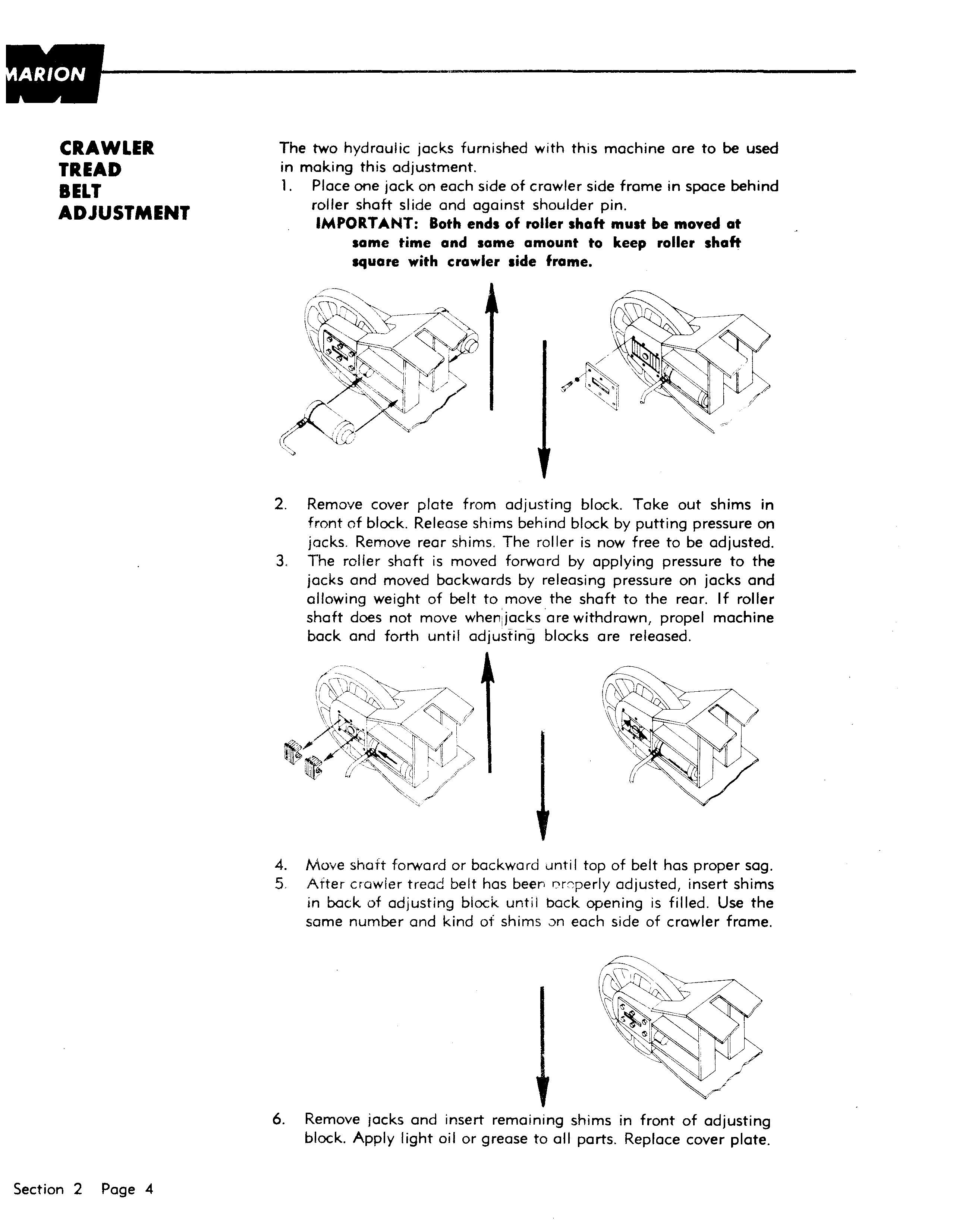
The two hydraulic jacks furnished with this machine are to be used in making this adjustment.
1. Place one jack on each side of crawler side frame in space behind roller shaft slide and against shoulder pin.
IMPORTANT: Both ends of roller shaft must be moved at same time and same amount to keep roller shaft square with crawler side frame.
2. Remove cover plate from adjusting block. Take out shims in front of block. Release shims behind block by putting pressure on jacks. Remove rear shims. The roller is now free to be adjusted.
3. The roller shaft is moved forward by applying pressure to the jacks and moved backwards by releasing pressure on jacks and allowing weight of belt to move the shaft to the rear. If roller shaft does not move whenliacksare withdrawn, propel machine back and forth until adjusting blocks are released.
4. Move shaft forward or backward until top of belt has proper sag. S After crawler tread belt has beer. r:w:perly adjusted, insert shims in back of adjusting block until back opening is filled. Use the same number and kind ot shims oJn each side of crawler frame.
6. Remove jacks and insert remaining shims in front of adjusting block. Apply light oil or grease to all parts. Replace cover plate.
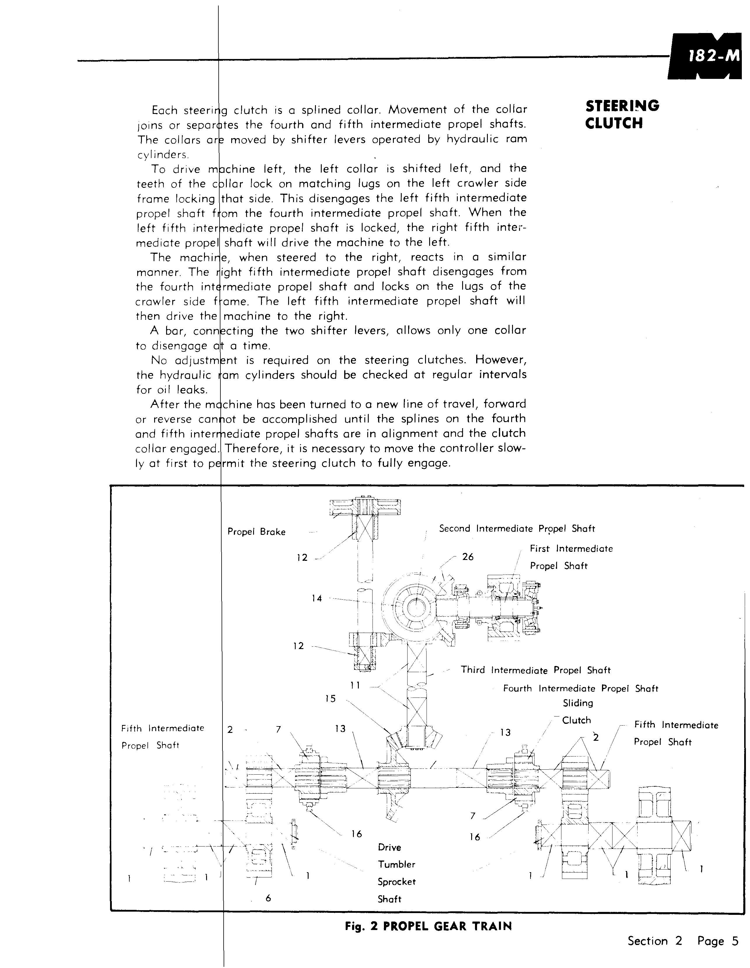
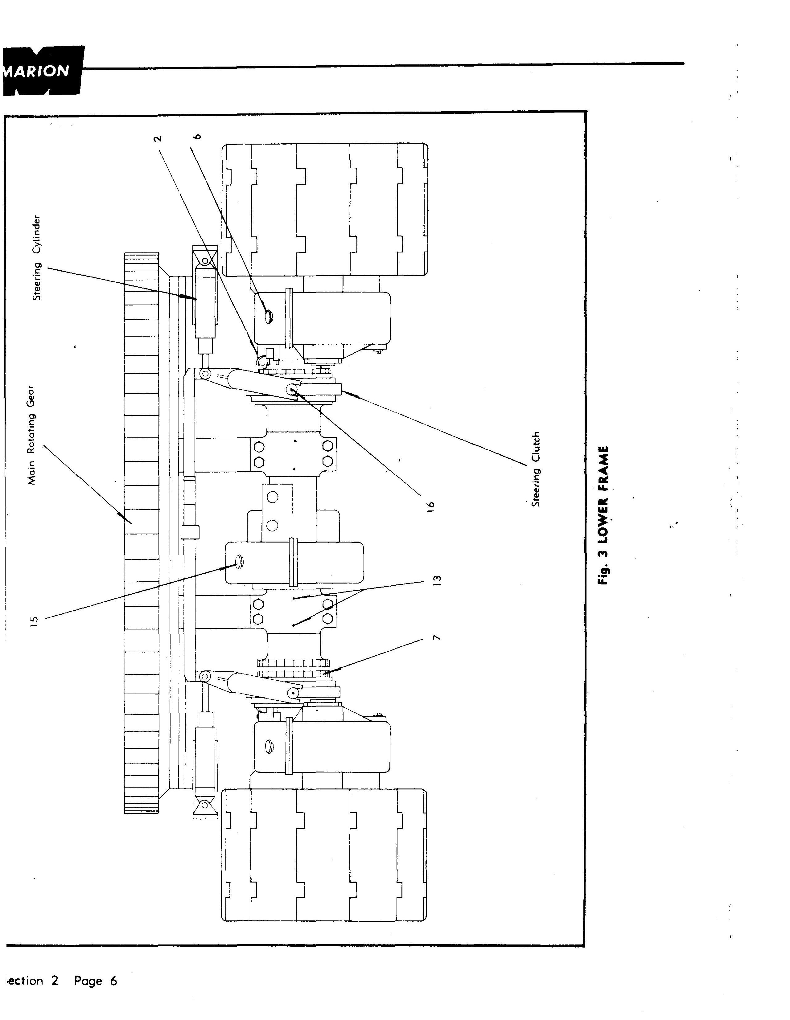
Each steeri g clutch is a splined collar. Movement of the collar JOinS or separ tes the fourth and fifth intermediate propel shafts. The collars moved by shifter levers operated by hydraulic ram cylinders.
To drive chine left, the left collar is shifted left, and the teeth of the c liar lock on matching lugs on the left crawler side frame locking that side. This disengages the left fifth intermediate propel shaft f om the fourth intermediate propel shaft. When the left fifth inter ediate propel shaft is locked, the right fifth intermediate propel shaft will drive the machine to the left.
The machi e, when steered to the right, reacts in a similar manner. The ight fifth intermediate propel shaft disengages from the fourth int rmediate propel shaft and locks on the lugs of the crawler side fame. The left fifth intermediate propel shaft will then drive the machine to the right.
A bar, conn cting the two shifter levers, Clilows only one collar to disengage aa time.
No adjustm nt is required on the steering clutches. However, the hydraulic am cylinders should be checked at regular intervals for oi I leaks.
After the m chine has been turned to a new line of travel, forward or reverse can ot be accomplished until the splines on the fourth and fifth inter ediate propel shafts are in alignment and the clutch collar engaged. Therefore, it is necessary to move the controller slowly at first to p rmit the steering clutch to fully engage.
• Thank you very much for reading the preview of the manual.
• You can download the complete manual from: www.heydownloads.com by clicking the link below
• Please note: If there is no response to CLICKING the link, please download this PDF first and then click on it.