Technical Manual
© Bucyrus All Rights Reserved
R
BI005998
BUCYRUS
• Thank you very much for reading the preview of the manual.
• You can download the complete manual from: www.heydownloads.com by clicking the link below
• Please note: If there is no response to CLICKING the link, please download this PDF first and then click on it.

CLICK HERE TO DOWNLOAD THE COMPLETE MANUAL
CLICK HERE TO DOWNLOAD THE COMPLETE MANUAL
OPERATION AND MAINTENANCE

INSTRUCTION MANUAL
No. 1012
MARION 1200 ELECTRIC WALKING DRAGLINE
Manufactured by
MARION POWER SHOVEL CO.
MARION. OHIO. U.$. A.
BI005998

BI005998 CONTENTS SEC TION PAGE 1>1. ;) :[hI :i I Erecting Instructions . :3 G. II Adjustments...... 3 16 III Operating Instructions . IV Lubrication Instructions V Wire Rope Reeving. VI Electrical Instructions VII Miscellaneous .... 29 37 57 62 95 No. 1012 4-1-54
SECTION I
ERECTING INSTRUCTIONS

MARION 7200 ELECTRIC
WALKING DRAGLINE
BI005998 No. 1012
-3- 4-1-54
These instructions have been prepared to aid in erecting a MARION 7200 Electric Walking Dragline, as a guide for the operator, the groundman, and the oiler in their operation, maintenance and lubrication. The engineering drawings which accompany the machine give the exact locc!tion of all parts, all necessary dimensions, etc. It is very important that extreme care be taken in assembly because improper erection may cause unnecessary wear and faulty operation of the machine.
When the is shipped from the factory, the parts are match marked throughout. Care should be taken to follow these match marks when the machine is assembled.
All finished surfaces and bearings are protected against corrosion and should be thoroughly cleaned just before assembly. When assembling, all bearings should be lubricated. Ball and roller bearings are to be filled only 1/2 full of the proper grease. Also lubricate all gears and put the proper oil in gear cases up to the correct level before the lnachine is run. All air and electrical equipment, bearings, and finished surfaces should be protected from the weather until the machine is fully assembled.
Select a level assembling area adjacent to the unloading point approximately 50' x 150 1 preferably made up of solid material and with good drainage. It may be advisable to place gravel or cinders in the immediate erection area.
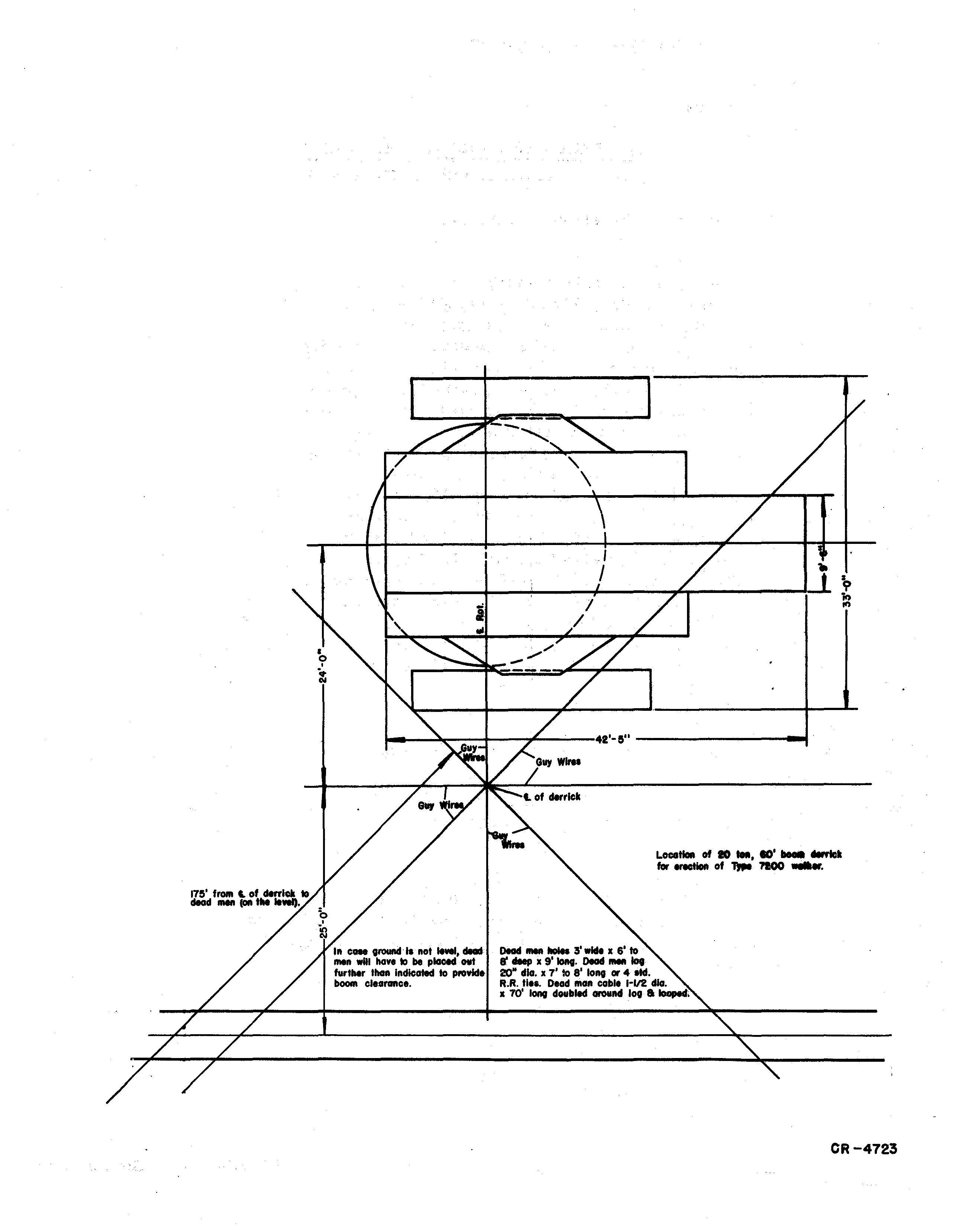
It is important that the derrick be placed so that the greatest loads can be lifted without interferring with the erection of the machine. The recommended position of this derrick is indicated on drawing CR-4723. If the ground is not level, place the dead men out further than the 175' indicated for boom clearance.
In the event that a2 to 2-1/2 yd. machine is available, for use as a lifting crane for unloading and placing of heavy pieces; it can be used instead of a derrick. This machine should have at least a 65 1 boom.
MATERIAL REQUIRED
(For Dome stic Shipment)
Following is a list of materials required to aid in the erection of the machine. They are to be furnished by the purchaser.
200 Standard railroad tie s
Miscellaneous flat blocking
8 Dead men logs for anchoring derrick guys, 20" diam. x 7' or 8' long, or can use 32 standard railroad ties
2 Bundle s of shingle s for shims
2 25 to 30 ton ratchet jacks
2 Track jacks
2 Low lift jacks with toes for low contact
2 85# railroad rails {for sliding upper frame off car and over tub
1 Cross cut saw
No. 1012 -4-
(Cont'd. on page 6)
BI005998
GENERAL
BI005998
Locetlall of • _. 10' lIIrrtcJl for .-tiGll of ,. 'l'IOO
...
Deod " wide x 6' to ff lIMp x 9' 1oIIt. Deod lot 20" dlo. x 7' 10 8' 10110 or" eN. R.R. tlea. Dead 11I011 cable '-1/2 dIG. x 70' Ion9 doubled _lid log a Iotlped;
I o I i
'" Qf'OlIIlCIIa not dead men will have 10 be placed OIIt furfur ItIall lndlcoted to proYlde b_ cle.rallce.
CR-4723
1 1-1/2 to 5 ton chain hoist
2 Crow bars
2 Pinch bars
2 Sledge hammers
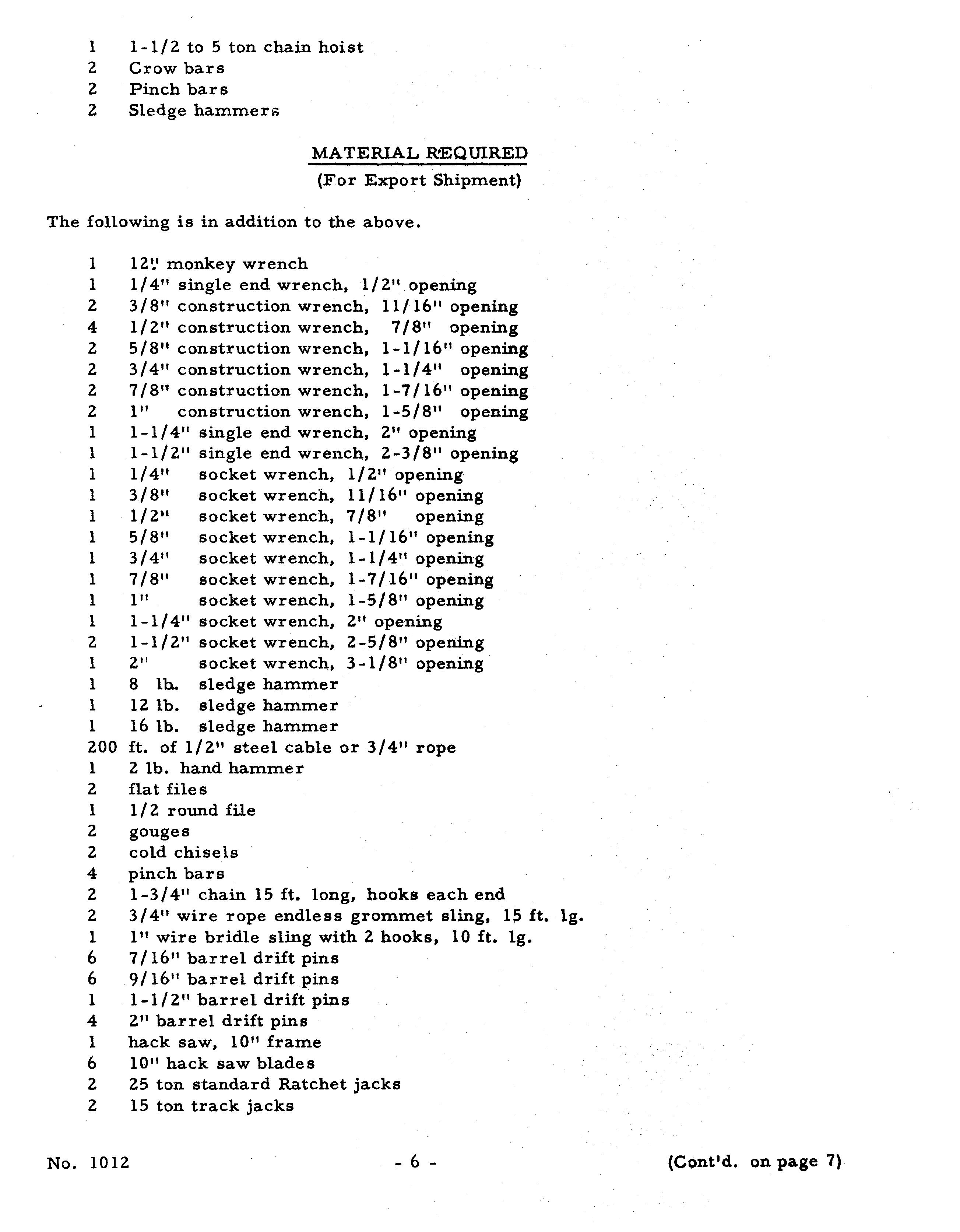
MATERIAL R!EQUIRED
(For Export Shipment)
The following is in addition to the above.
monkey wrench
1/4" single end wrench, 1/2 11 opening
3/8" construction wrench, 11/16 11 opening
1/2" construction wrench, 7/8 11 opening
5/8" construction wrench, 1-1/16" opening
3/4" construction wrench, 1-1/4" opening
7 /8" construction wrench, 1-7/16" opening
1" construction wrench, 1-5/8" opening
1-1/4" single end wrench, 2" opening
1-1/2" single end wrench, 2-3/8 11 opening
1/4" socket wrench, 1/2" opening
3/8" socket wrench, 11 /16 11 opening
1/2t! socket wrench, 7/8" opening
5/8 11 socket wrench, 1-1/16" opening
3/4" socket wrench, 1-1/4" opening
7/8 11 socket wrench, 1-7/16 11 opening
111 socket wrench, 1-5/8" opening
1-1/4 11 socket wrench, 2" opening
1-1/2 11 socket wrench, 2-5/8" opening
2" socket wrench, 3-1/8" opening
8 lho sledge hammer
12 lb. sledge hammer
16 lb. sledge hammer
ft. of 1/2" steel cable or 3/4" rope
2 lb. hand hammer
flat files
1/2 round file
gouges
cold chisels
pinch bars
1-3/4" chain 15 ft. long, hooks each end
3/4" wire rope endless grommet sling, 15 ft.
III wire bridle sling with 2 hooks, 10 ft. Ig.
7/16" barrel drift pins
9/1611 barrel drift pins
1-1/2" barrel drift pins
2" barrel drift pins
hack saw, 10" frame
10" hack saw blades
25 ton standard Ratchet jacks
15 ton track jacks
No. 1012
BI005998
1 1 2 4 2 2 2 2 1 1 1 1 1 1 1 1 1 1 2 1 1 1 1 200 1 2 1 2 2 4 2 2 1 6 6 1 4 1 6 2 2
Ig.
-6-
(Cont1d. on page 7)
12 man cross cut. saw
15 ton chain hoi st
2 crowbars
2 pinch bars
5 gallons cleaning solvent
1 lifting crane capable of handling 20 tons at a 20 foot radius and having a 50 foot boom
ELECTRICAL TOOLS
1 4" screw driver
2 8" screw drivers
1 pro 8" pliers, side cutting
1 pro 8" long nosed pliers
1 pro 10" gas pliers
1 12" mill file
1 12" double cut file
2 12" half round file
1 8" round file
1 1/4" to 3/4" pipe bender
1 10" Stilson wrench
1 lOti crescent single end wrench
1 6" crescent single end wrench
2 18" pipe wrenches
1 cold chisel
1 gouge
1 1-1/2 lb. hammer 11 qt. blow torch
50 I steel fish tape
1 doorbell with 2 new dry cells (or a meggar)
1 set of 3/16 steel letters
1 set of 3/16 steel figures
MISCELLANEOUS ELECTRICAL SUPPLIES

BI005998
1 3/8 x4 U-Bolt for 2" conduit 2 3/8 x 3-1/2 U-Bolt for 1-1/2" conduit 1 1/4 x 2 U-Bolt for 3/4" conduit 10 1/4 x 1-5/8 U-Bolt for 1/2" conduit 3 1/2 x 2 Mach. Bolts W/Nuts & Lock Washers 5 1/2 x 1-1/2 Mach. Bolts W/Nuts & Lock Washers 2 3/8 x 1-1/2 Mach. Bolts W/Nuts& Lock Washers 2 3/8 x 1-1/4 Mach. Bolts W/Nuts & Lock Wasbe,rs 1 5/16 x 1 Mach. Bolts W!Nuts & Lock Washers 5 1/4 x1 Mach. Bolts W INuts & Lock Washers 1 1/2 x 1-1/2 Cap Screw W/Lock Washers 10 1/4 x 20 x 1 Round Hd. Brass ,Mach. Screws W!Br-ass Nuts 4 1/4 x 3/4 Cap Screws W/Lock Washers 8 #14-24 x 1 7 1/4 Round Hd. Brass Mach. Screws WlBrassNuts 10 # 14-24 x 1 Round Hd. Brass Mach. Screws W!:B-rass Nuts 15 #10-32 x1 Round Hd. Brass Mach. No. d012 -7- (Cont'd. on page 8)
#10-24 x1 Round Hd. Brass Mach. Screws W/Brass Nuts # 4-36 x 1/2 Round Hd. Brass Mach. Screws W/Brass Nuts
1/2 x 1-1/8 Conduit Nipples
2" Box Connectors
1-1/2" Box Connector
1-1/4" Box Connector
1" Box Connectors
3/4" Box Connectors
1/2" Box Connectors

2-1/2" Conduit Bushing
2 1f Conduit Bushings
1 -1/2 11 Conduit Bushing
1-1/4" Conduit Bushing
I" Conduit Bushings
3/4" Conduit Bushings
1/2" Conduit Bushings
1" Conduit Lock Nut
3/4" Conduit Lock Nut
1/2" Conduit Lock Nuts
2-1/2" Conduit Coupling
2" Conduit Coupling
2 ft Combination Couplings
1/2" Combination Couplings
1/2" Conduit Clamps
1-1/2" Conduit Straps
1-1/4" Conduit Straps
I" Conduit Straps
3/4" Conduit Straps
1/2" Conduit Straps
Copper Terminals #10 & 12 (Solderless)
Copper Terminals #8, 10 & 12
Copper Terminals #6
Copper Terminals #4
Copper Terminals #000
Rolls 3/4" Varnish Cambric Tape
Rolls 3/4" Black Friction Tape
lbs. Soldering Paste
1bs. Half & Half Solder
lbs. Wire Solder
qt. Glyptal Lacquer
sheets 00 sandpaper
TOOLS AND EQUIPMENT
It is recommended that a small tool room be erected at the erection site for the protection of the tools, drawings, etc.
One electric welding machine is required to be used throughout the erection period. Consult Marion Power Shovel Company regarding derricks, tools and other equipment for use when erecting the machine.
No. 1012 -8-
BI005998 4 8 2 2 1 1 2 2 4 1 4 1 1 3 2 10 1 1 5 1 1 1 2 6 2 2 2 3 3 12 4 2 4 20 2 4 1/2 2 2 2 5
ERECTION PROCEDURE
It h recommended that the following procedure be used in erecting the machine.

1. Assemble lower frame or tub.
a.Build a crib, preferably of railroad ties, approximately 30 li high to allow for riveting and bolting underneath tub.
b. Place center section on crib.
c. Place outer sections and pull sections together, align and bolt. Tub should be leveled and circle rail bearing surface be checked for levelness with transit.
d. Bolt tub complete.
e. Bolt on wearing plates and cleats.
f. Remove cribbing and lower the tub to ground. (If erecting the machine in the winter, it may be advisable tc> lower the tub to a mat of timber, clear of the cleats, under the edge of the tub, to prevent freezing the tub to the ground).
2. Install gear segments being sure to follow match-
3. Install lower circle rail and bolt to tub, using wedge was-hers" urid-er nut.
4. Install center journal.
5. Assemble roller circle.
6. Install upper circle rails on the roller circle in such a p-osition that boom end of upper frame will be pointed toward der1:"ieki.
7. Burn off lifting lugs and grind smooth.
8. Assemble sections of rotating frame.
a. In assembling the upper frame, the electrician should':instaH the conduit, wiring and electrical equipment simultaneously with erectors to avoid being blocked out.
b. Place center section of upp.er frame. Be sure centerjc1'l1rnal' is well greased and shear blocks welded inptace before' pla'Cing center section over it.
c. Assemble main swing shaft' and swing gear ca'se oncente'l:' section of upper frame.
d. Install right and left wing.sections andbolttocente'l' se'ttion'.
BI005998
No.
-9- (Conttd': on page 10)
1012
9. Build secure crib under rear of machine to support ballast and machinery.
10. Install ballast as indicated in print L. P. 278. Ballast should be distributed in accordance with these instructions so that the machine will be properly balanced when in operation.

11. Place all machinery on upper frame, including motor generator set, electrical equipment and necessary wiring in the order outlined below. The motor generator set and electrical cabinet may be placed at any convenient time while machine is being installed.
a. Bolt on hoist and drag machinery and install hoist and drag drum.
b. Install swing motors and oil pumps for swing gear cases.
c. Place main propel gear and install main propel shafts.
d. Install boom hoist machinery.
e. Install main drive gear case.
f. Install air compressor.
12. Install lower cross beams of superstructure and bolt.
13. Install fairlead.
14. Install stub shafts and walking towers. Align and bolt. It is particularly important that match marks be followed exactly during this installation.
15. Install house front and rear.
16. Place roof trusses and eve angles.
17. Place operator I scab.
18. Assemble upper structure.
19. Install gantry cap.
20. Weld stiff legs top and bottom.
21. Install house roof. (Before roof is installed, keep machinery and electrical equipment well covered).
22. Connect boom to rotating frame. (Connect boom foot section first to the upper frame and build the rest of the boom from foot section).
23. Reeve cables. Reeve boom hoist cables first. Reeving is more easily accomplished by welding or brazing a 1/2" by 200' (or longer) cable to one No. 1012
BI005998
-
10 - (Cont'd. on page 12)

BI005998 BALLAST 80X( $ H POCKET 100J' CAP. CAP. CU. FT. CU.FT. • A B C o E F' G H J TOTAL £ B41 27 4Z 27 11,) 11 AT 250 LB$. PER CU.F'T. 42;01150.0 615°425 0 11500 6750 2500 7750' 59500L.R278
end of the bOOIll hoist cable. After threading this sIllaller cable by hand as far as it will go, pull bOOIll cable through with the 1/2" cable. After connecting bOOIll hoist cable to the bOOIll hoist, pull up taut (with bOOIll still on ground). See Cable Reeving Section.
24. Install air piping.
25. COIllplete house.
26. Install walking cranks and walking shoes.
27. Raise bOOIll and reIllove cribbing at rear of Illachine.
28. Make all necessary adjustIllents and cOIllpletely recheck the Illachine for any loose bolts, nuts, cotters or errors in as seIllbly. ReIllove all tools and equipIllent. Check all Illoving parts for obstructions which Illay cause daIllage.

29. Install the proper type and aIllount of oil in all gear cases and cOIllple.tely lubricate the Illachine with type of lubricant recoIllIllended in the Lubrication Section.
CAUTION: Machine is shipped less fluid lubricant in gear cases. Make sure that they are filled.
painting is cOIllpleted, the Illachine is ready for testing and Illaking electrical settings.
BI005998
- 12 -
No. 1012
• Thank you very much for reading the preview of the manual.
• You can download the complete manual from: www.heydownloads.com by clicking the link below
• Please note: If there is no response to CLICKING the link, please download this PDF first and then click on it.
CLICK HERE TO DOWNLOAD THE COMPLETE MANUAL
CLICK HERE TO DOWNLOAD THE COMPLETE MANUAL