Cat Bucyrus Marietta 3612 Drum Miner Maintenance Manual PN 6001 0001 – PDF DOWNLOAD

Page 1

Technical Manual

© Bucyrus All Rights Reserved
R
BI000089
BUCYRUS

• Thank you very much for reading the preview of the manual.

• You can download the complete manual from: www.heydownloads.com by clicking the link below

• Please note: If there is no response to CLICKING the link, please download this PDF first and then click on it.

CLICK HERE TO DOWNLOAD THE COMPLETE MANUAL

PART NUM'BER 6001' 0001

.: . - -..••.• .:.: .. N--:,.. , ::,i':> ::',' ,'/ ,; ;" -,'-....' .. ,i',' ; .. ,;
:.t .,' I- ::.(: ·17-, BI000089

,1i;.,I'.' 'e-all Th'.FOlto

Mine SerVice Company

,p :0. Box 775

Bentol1, lL 62812

Box 502, R.D. 1 Blairsville, PA 15717

P.O. -Box 1100 ' WV 24701

p.O. Box 159 is'ol t ,WV 25817

P.O. Box 1247

Madisonville, KY 42431

P.O. Box 870 Martin, KY 41649

o. Box 9g8 KY 40965

P.O.' Box 844

GlenloJbOd'Spri!lgs', CO 81601

PwO. ,Drawer 1755 ;':Price, 'liT 84501

P.O. Box 1080 PA15310

P.O. Box 630 Wise, VA 24293

Hager Equipment Company, 1601 25th Avenue North Bessemer, AL 35023

'36·l2 DRUM MINER- DATA

THE WiTittN' IS"

BECAUSE OF THE MANY VARIATIONS OF THE 'MARIETTAR DRUM MINERS PRODUCED

NO DRAWING WILL APPLY TO ALL MINERS. THEREFORE, THE DRAWINGS CONTAINED TN THIS MAINTENANCE BOOK ARE TYPICAL,. FOR SPECIFIC DRAWINGS AND FOR ORDERING PARTS, REFER TO THE PARTS MANUAL SUPPLIED WITH THE MACHINE.

': ".',.' EIMCQ Mining . -, International , -.:. .: .,! ;-
, ,C;"._ :.,"
(618) 439-7506 ,( 412) 24,8-7S11 (304) 325-0481 . (384) ,934" 53,51 (502) 821- 2070 (606) 285-3236 (606) 248-1371 (303 ) 945-7836 (801) 63:7 -1434 ( 412) 627-99'13
679-0194 (205) 424-1363 Eimco Mining Machinery International IS a unit 01 Baker Mining Company
(703)
CHANGE WITHOUT NOTICE
SUBJECr:t1- TO"
DECEMBER 1986
BI000089
2667MM , .7'-3'" 2209.8MM - 'I t663.7MM 41;11' 1041.4MM • L_=3 11 298.5MM 53" 1346.2MM 36" 914.4MM 52'# 1320.8MM OVER BOOM PIVOT OPTIONAL :-------3"'-76.2MM CRAWLER ADJ 1I!.. 0" 3352.8MM 6" 3352.8 MM 12'0" 3657.6MM 44· 1118MM I 44N 1118MM 12'-0'" 3657.6MM ...___ -----:-= 9'____ 6'-10"_-:---_-.....___ 8'-9" ____ ---II-t4____ 9'-IO" __ _____..t 2743.2 MM 34"- '!:r__-....--·2-0-8-2-.8-M-M--------r---2-6-6.,.--7-M-M-------------'-2-9-91-.2'--M_M_____ WHEN GATHERING HEAD IS AT GRADE 14------------------I0490.2MM REF. DRAWING 9108 6884-F 3612 DRUM MINER OPERATINC DIMENSIONS I LEVEL . z.-8S I BI000089
I / I '/ 52'" J320.8MM OPTIONAL ( ) ----\ , 7'-1"'- 2159MM 38"-965.2MM OVER BOOM PIVOT 36# 914.4MM 18" 457.2MM 12"" 304.8MM • , 5?t 1346.-2MM 36" 914.4M'V1 ----------CRAWLER ADJ. 9'-0" ________ ......-----6'-10"----.... _____ 8'-9N _____ ------::"2":::-743.2MM 34'-e1-"--..;..._20_8_2_,.8_M_M________2_6_6_7M_M__________2_9_97._,2_M_M________ ...--------------:::I0490.2MM REF.' DRAWING 91086884-F 3612 DRUM MINER OPERATINC DIMENSIONS (('-0'" 3352.8MM 3352.8 MM • 1 12'0'" 3651.6MM 44# IIISMM f IZ-O3657.6MM ; 44N 1118MM IIN -279MM WHEN GATHERING HEAD IS AT GRADE j..EVEL 19100 0597-LMOI .1-1- 85 BI000089

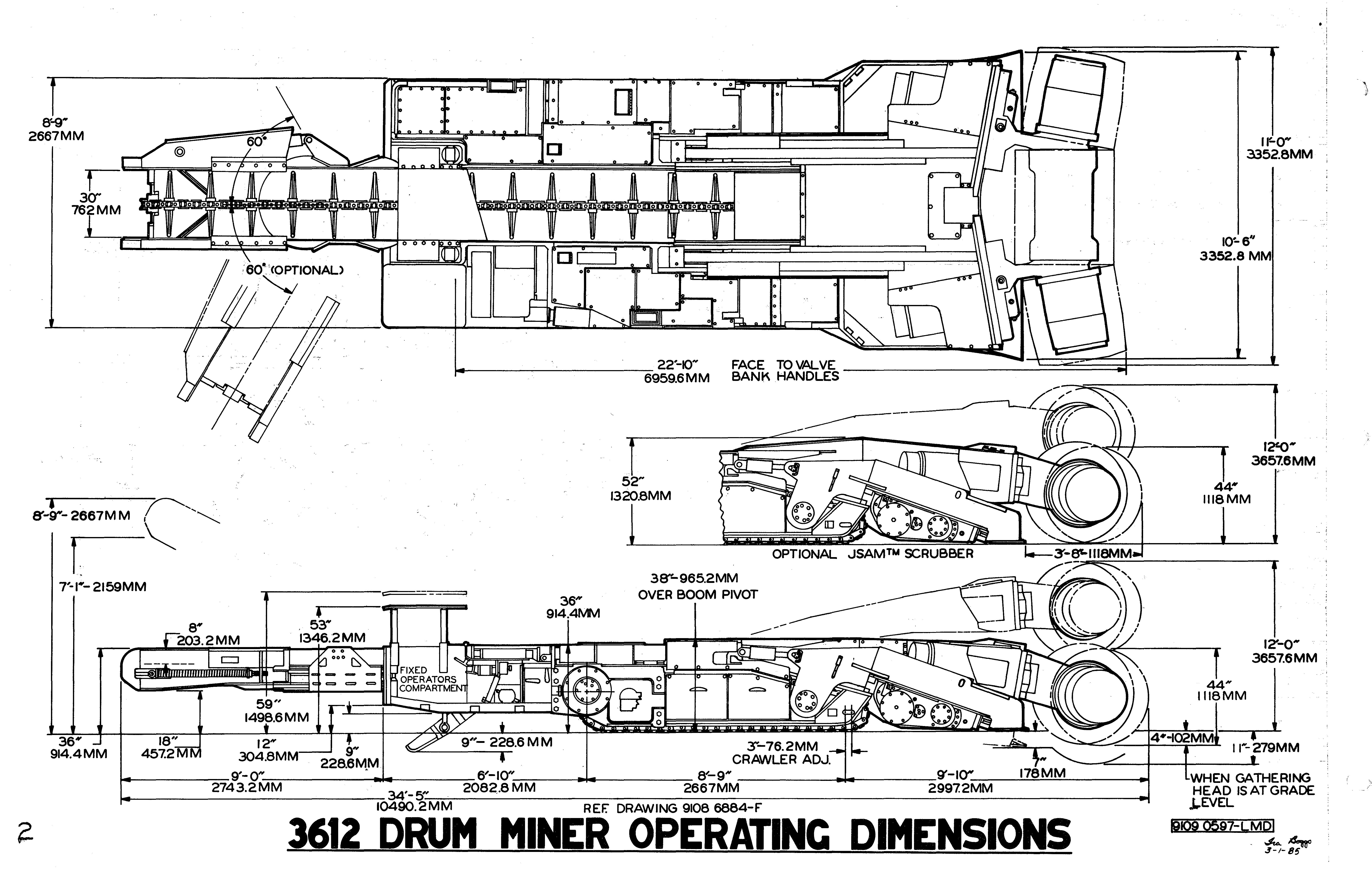
STANDARD FOR 3612 MARIETTA DRUM MINER

Tranuning Height

·*With ScrUbber

Tranuning, Width

, Chassis Height

'Chassis Width

*With Scrubber

Conveyor Boom Height

Conveyor Swing

Conveyor Inside Depth

conveyor Inside Width

Machine Length

Crawler Track Width

Cutter

Mac:hine , Weight

Ground Clearance

Center of Gravity

Traction Surface

Ground Pressure

Gathering Head Travel

Gathering Head Width'

Mining Height

Mining Width

Cutter '-Drum Travel

44", (at cutterhead)

11' , (at, cutterhead) ,

8' - 9"

38" ,(boo:m fully l()wered)

52'" (bpom fully 'lower-ed)

7' - 3" (45 0 boom fully raised)

8' - 9" (60 0 boom fully raised)

Std. 45 0 (right or left)

Opt. 60 0 (right or left)

12" (45 0 boom)

8" (60 0 boom)

-

of front idler) 4368 sq. in.

Maximum up 23"

Maximum down

- 6" 4' to 12' II'

4" below grade (gathering head on grade)·

11" below grade (gathering head below grade)

cutter Drum Speed

Cutter Bit Speed

Gathering Arm Speed

Conveyor Speed

Tram Speed

DC Tram Motors (2 req'd)

AC Pump Motor

AC Gathering Head/

'AC Cut;ter p,rum.Motor

\
36"
52"
34'
30"
5" 21" 42" or 44" 120,000 lbs. 9" or 12" 36 11 '( from center
27 PSI
10'
(2 . "
Trailin.g Cable Size
Tandem Hydraulic Pump Hydraulic Oil Capacity
Gear Case Lube Capacity
Types of Machine Control 40 RPM, 48 RPM, or -57 RPM 440 FPM, 528 FPM,or 627 -FPM - 42" Drum 460 FPM, 55'3 FPM, or 656 FPM - 44" Drum 54 RPM 429 FPM 0 to 52 FPM 37 HP at RPM 70 at 1775 RPM 80 HP at 1125 RPM 200 ijP at 1775 RPM 624 HP 44,0 v. 550 v. 950 v. 1000' Max. Type GGC 4/0 1000' Max. TYpe GGC 4/0 800' Max. Type SHD-GC 1/0 33 GPM section for cylinder functions and 22 GPM section for pilot circuit 100 U.S. gallons
Drive -
S.
Drive -8 U. S. gallons each Gat:her:i.'ngHead Pot -5 U. S. gallons each ijeadPrimary - 9 U. S. gallons
On Manual Control
Radio Remote Control 3 BI000089
T.Qtal
1
Approximate
2
Drum
15 U.
gallons each
1.
2.

IMPORTANT FEATURES INCORPORATED ON 3612 MARIETTA DRUM MINER

MqH. \C '10 r:· {;I;";":J New genera t on rugged pI aneta ry cu t terhead d rive prov ding" 1ow '" thus helping. reduce dust and challl-C_e qf ignition.

Patented canted-end cutterhead for coreless cutting and maximum

:, '..,;sumping. Simplified maintenance - Quick change cutter: drums without loss of lubricant.

ReI iable wet, multi-disc type ut.ilized in the gathering/ conveyor drive and dry clutchesutilized in the cutterhead drive.'···· '" . .:1- ,-" r

DC tram drive .'

NMS high output system.

Stecko hose fittLI]£? of hoses and components.-· - ." lrU... ".,. H.;;._ U ..1-. (b 'ps:! 0':1.;

Water deluge fire and dust when required. 'J ':: ls.:tol1

JSAMT available as option. '. 'K - '. :. '. :::

Rugged' 36 "11 ig h Ch'a $ s i .... . , G:; (: .:.

Adus tab 1e safety prop for the conveY9r:' and cutter booms t.h; can be worked under safe 1y.:.while in': a ra i sed pos '.:

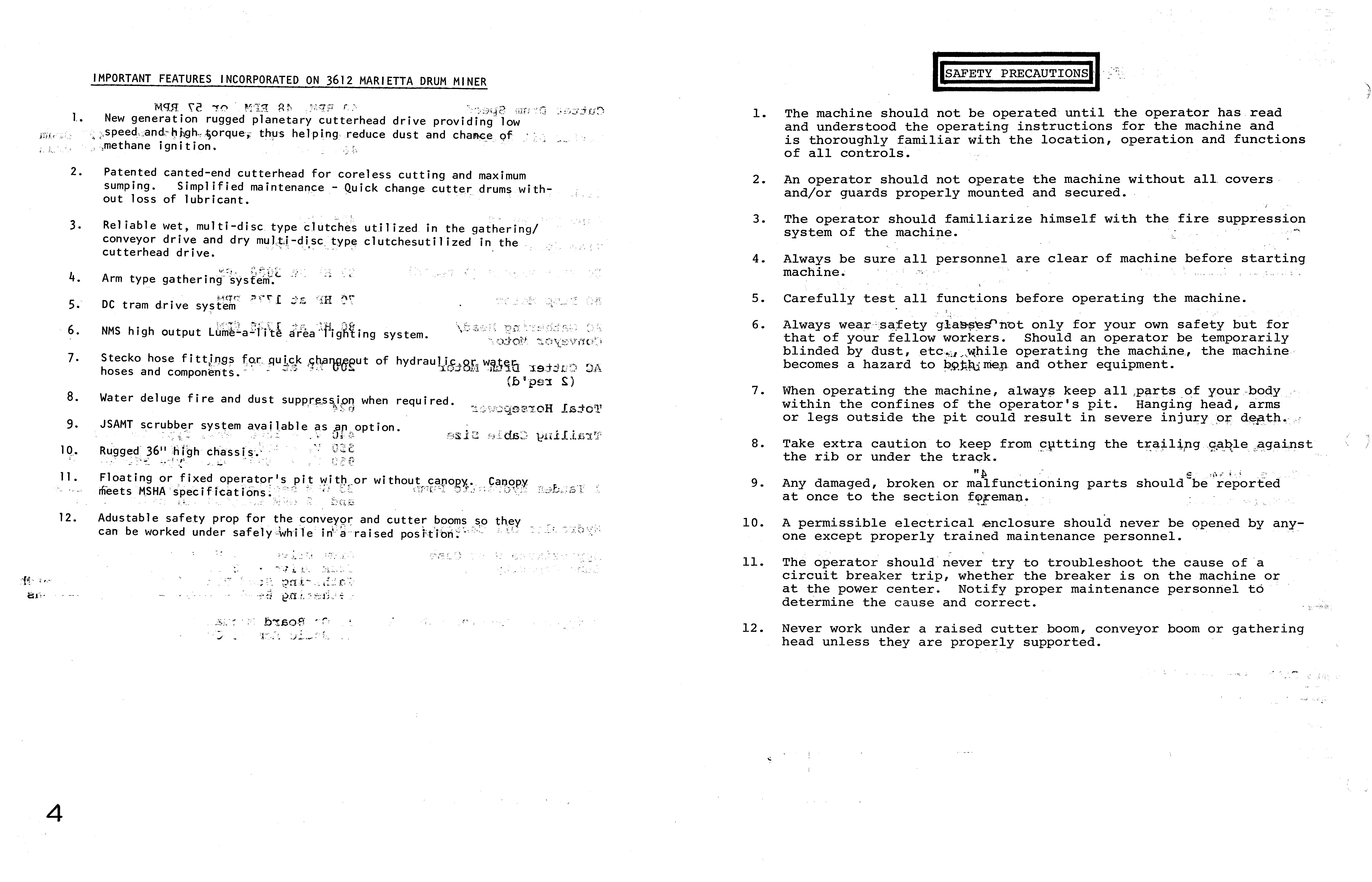
1. The machine should not be operated until the operator has read and understood the operating instructions for the machine and is thoroughly familiar with the location, operation and functions of all controls.

2. An operator should not operate the machine without all. covers and/or guards properly mounted and secured.

3. The operator should familiarize himself with the fire suppression system of the machine.

4. Always be sure all personnel are clear of machine before starting machine.

5. Carefully test all functions before operating the machine.

6. Always only for your own safety but for that of your fellow workers. Should an operator be temporarily blinded by dust, etc·.a .. operating the machine, the machine becomes a hazard to and other equipment.

7. When operating the machine, keep all .of your ·body· within the confines of the operator's pit. Hanging head, arms or legs outside the pit could result in severe injury,o+,

8. Take extra caution to keep from cptting the the rib or under the traQk.'·-

9. Any damaged, broken or malfunctioning parts should -be" reported at once to the section

10. A permissible electrical .enclosure should never be opened by any:one except properly trained maintenance personnel.

11. 12.

The operator should never try to troubleshoot the cause ofa circuit breaker trip, whether the breaker is on the machine or at the power center. Notify proper maintenance personnel to the cause and correct.

Never work under a raised cutter boom, conveyor boom or gathering head unless they are properly supported.

i,O:.,_ 1.. 2. 3. 4. 5. 6. 7. 8. 9. 19· 11. 12. 4
- -':. " - (: {!
. ,: -:' --.; 1. to, ?!1 t -. .:.' .:. :-,::.rL' .
"
.- .c: \.....
BI000089

RECOMMENDED STEPS TO FOLLOW WHEN OPERATING THE 3612 MINER (Individual mines may require different cycles of operation.)

STEP

OPERATING PROCEDURE

1. Make sure that everyone is clear of the machine and all valves, breakers and switches are in the neu,tral or off position.

2. Make sure proper voltage is being supplied to the machine. Make sure water is being supplied to the machine.

4. Turn on main circuit breaker.

5. Turn on control circuit breakers.

6. Turn on area lights.

7. Select and turn on control valve for directional water spray.

8. Turn on headlights.

9. Start pump motor.

10. Raise or lower conveyor and cutter boom for adequate clearance 'and visibility •

11. Put gathering head in float position. For maximum cleanup efficiency, the gathering head should rest against the mine floor and be free to float.

12. Tram machine to the face until cutterhead just touches face.

13. Position the rear conveyor over the shuttle car by raising and swinging to desired position.

14. Raise the cutter boom to the desired cutting height.

15. Start the gathering head/conveyor motor.

16. Activate water spray system.

17. Start cutterhead motors.

18. Lower stabilizer shoe to help stabilize machine during sumping and shearing operation, if required.

19. Sump the cutter head into the face by pushing tram levers forward. Tram machine forward until it has advanced approximately 30" into the top of face.

20. Lower cutting head down, thus shearing the face. Do not tram during the shearing cycle.

21. When head has reached bottom, release shear switch, raise stabilizer shoe and tram machine backward approximately 3'''' thus trimming ridges and smoothing bottom. Make certain shuttlecar is clear before backing miner.

22. Raise the cutterheadand repeat cycle (19 thru 22) until desired amount of face has been cut.

23. Turning crosscuts is accomplished by making a series of partial cuts until the machine can be turned to the desired angle.

)
5 BI000089
6 TRAC TOR FRAME WT.. 69,400 LBS (31.5 MT) 8'-9'1 (2667 MM) 10'-11" <3327MM) OR GATHERING HEAD WT. II,OOOLBS • , · + 3'2/' 38" · .I (5055 MM> , 4'-7// (1397 MM) ... 14-------19'-ON (579( MM) J. CONVEYOR (OPTIONAL 60oSWING) WT. 7,400 LBS (3.4MT) t 8'-1"----<.2464 MM) CONVEYOR CHAIN SECTIONS=50 -=''::::====:::::::d, 2'-0" REF. DRAWING • C6(OMM) .9108 5597-C CUTTER HEAD WT. 36JOOOLBS 11'-0 '/ (3353MM) <l6.3MT> I ---""1::?:_______.... ' IfJJ .----15'-4"( 4674MMJ --'1IILO'I (3353MM) CUTTER HEAD W I SCRUBBER SYSTEM WT. 38,000 LBSc_1..-..:,7.=-2 ___ \ 42'U067MM) WITH &ITS "-;::..Jf 3612 DISASSEMBLED SECTIONS 19109 2601- LMBI 5 BI000089
\ L II (OPTIONAL srfSWINO SHOWN) CONVEYOR ASSEMBLY .CUTTERHEAD ASSEMBLY TRAC OR FRAME ASSEMBLY 3612 .. "AJOR._AS$EMBLIES GATHERING HEAD ASSEMBLY' 7 19109 2676-LMDI BI000089

6011 9625 B CONVEYOR PROP USE FOR CONVEYOR SUPPORT DURING MAINTENANCE. ENDS OF PROP ENGAGE HOLES ON TRACTOR FRAME & CONVEYOR

PIN 6012 0367

& DANGER KEEP CLEAR CONVEYOR MAY SWING RAPIDLY WITHOUT WARNING

PIN ·6012 4062

MSHA

THIS CAB OR CANOPY, PART HAS BEEN DESIGNED TO MEET OR EXCEED THE MINIMUM REQUIREMENTS FOR STRUCTURAL CAPACITY SET FORTH IN 30 C.F. R. SECTION 75.1710-1, PARAGRAPH D- \\ TO SUPPORT ELASTICALLY, A DEADWEIGHT LOAD Of 18000 POUNDS, OR 15 PSI DISTRIBUTED UNifORMLY OVER THE PLAN VIEW AREA OF THE STRUTURE, WHICHEVER IS LESSER." CERTIfiCATION IS VOID If CAB OR CANOPY IS MODifiED IN ANY MANNER. WITHOUT EX PRESS WRITTEN APPROVAL

PIN 6418 6356

ASSEMBLY NO. ___ _____ CERTifiED AS COMPLYING WITH THE APPLICABLE

COMMONWEAL TH OF PENNSYLVANIA

APPROVAL NO 1 _____

PIN 3014 5635

MAIETTA "UM MINtR PATENT PENDING

REQUIREMENTS Of 30 C.F.R. At>.RT 18 CERTIFICATION NO. - X/P-

PIN 6411 8235

CAUTION

PIN 6012 7503

PERMISSIBLE CONTINUOUS MINER

CAUTION

BOOM PROP ONLY TO BE USED WITH PART NO. 9108 8492

PIN 3014 6252

PIN 9108 8666 TYPICAL 3612 TAC LOCATIONS

DO NOT WORK UNDER CUTTER BOOM OR CONVEYOR WITHOUT SUPPORT PIN 6000 8000 '*ADDITIONAL LOCATION) 19109 I

8
TYPE SERIAL t-D. POWER DATE -"':"':"'=-=---'11 II I &-1 __ -'
APPROVAL. ______ TVPE ________ ThiS approval Clnd +hls plate apply only when thIS unl IS m.lhtalned In accordattCGt With MSHA perm" blhty requU"ements SERIAL
»---
LMDJ \ ) BI000089
199
i' I" .." ".. .'. -' .', .'>' LIIER,lh{y'OESCRIPTI3:N; , < .•.. :::: :t:::::: ::: ry Gear, Case G1 ....•......•.............. 29 .. Pri.ma;.ri GeaF'Case 3D RepJacement·ofG'atheri ng HeadGear Case (Pot}, _ ; .......•........... 30&31 ng Shaft... ........ " .....•.............. ...... 32 Re'pTacemetttbf Gather; ng Head Fbotsna ft............•........................ 32 DRAWINGS -' "." 3q12UrllhMi ne r Gear Chart (9109 2R19 U1Q) ............. : . • . . . . ... . . •• 2 (9107 6299 LMD). 3 3612l"Y'actor Frame/Pa rtIdenti fi cation. . ..• . . . . . . . . .. . . . . .. . • . . . . . • .. 6 3ql.2,Ira$tor LMD). .•.. •• ..7 ew (9109 0605 LMD) ........••.•.••103g1Zrram,Drive (9107 6323 LMD) ..............••.. 11 lra!l1Drive ( ) .................•......•.12 3;61g .. ve AsseJ11bly/Part Identification 13 3912 ve Pri mary Gear Kit (9104 0006 LMF) ..................••. 14 1er Assembly' (9109,1090, ..........................•. 15 Bel tAdjus (91092635 LMD) .......................•. 16 cation ...................•......... 7.20 Ass<=mbly (91090688 LMD) .................................... 21 ly System )JPa rt Identi fi cati on ............•. 22 (SGrubber System) (91096453 LMD) ................. 23 veAssemblY7Expl oded View, (91088153 LMD) .........•..... 24 -tl00 CutterheadDri ve-,Secti on View (9107 6315 LMD) 25 +100 Cutter head TorqueL;mitfng Clutch (9108 8187 LMC) ............... 26 Identification ....................•.•.. 27 3fj12 fpotShaft As semb Ty( 9109 1116 1MB) .•........•............ ..... '33 3g12 Gathering Head Assembly/Part Identi fi cati on ............•......... 34 H<=acf Assembly-With Corner Scrapers (9109 0621 LMD) ...• 35 3Q12Gatijeri ng Head Assembly/Part Identiffi cation 36 3612 Gathering Head Assembly (9109 8277 37 3612 Primary Gear Case Assembly/Part Identification 38 3612 Primary Gear Case Assembly (9106 5219 LMF) .....•................ 39 3612 Gathering Read Gear Case Assembly (Pot)/Part Identification ..... 40 Gathering Head Gear Case Assembly (Pot) (9103 9495 LMD) 41 3612 (45 0 Swing) Conveyor Assembly/Part Identification ............... 42 3612 (45° Swing) Conveyor Assembly (9109 8210 LMD) 43 3612 (60 0 Swing) Conveyor Assembly/Part Identification .......-•....... 44 3612 (60 0 Swing) Conveyor Assembly (91091033 LMD) ................... 45 BI000089

GEARING SETUP

The 3612 Miner contains four completely separate main drive systems. They are tram, pump, gathering head/conveyor and cutter drum.

The Tram System consists of two separate drives, one for the left track and the other for the right track. The tram system works on the principle of a motor driving a shaft which drives a right angle drive and a primary planetary, which then drives a tram gear case containing three helical gears. Power is transferred through these gears to the sprocket shaft, which drives the track. birection of travel is determined by the direction the motor shaft is made to rotate.

The Pump System consists of a motor driving a shaft which drives a coupling assembly. Power is transferred through a coupling assembly to the hydraulic pump. The pump motor should rotate counter clockwise when viewed from the output shaft side, thus providing correct hydraulic pump rotation.

The Gathering Head and Conveyor System consists of one motor, on the left side of the machine. The power is transferred from the motor to the primary gear case, which is located on the right side of the gathering head,by means of a prop shaft. The primary gear case contains two helical gears and three spur gears and a clutch. The primary supplies power to the right side gathering head gear case. The gathering head gear case contains a coupling which drives a pinion. The pinion drives a ring gear which is connected to a table that rotates, causing the gathering arms to work. At the same time, the foot shaft sprocket turns, causing the conveyor chain and left hand gathering head gear case to work. This is accomplished by a coupling which connects the foot shaft to the gear case pinion.

The direction the conveyor chain and gathering arms move is determined by the direction the motor shaft is made to rotate. The clutch in the primary gear case allows slippage in the system, in case of blockage on the gathering arms or conveyor chain. The clutch is factory pre-set to the correct torque setting but should be checked periodically to make sure proper adjustment is maintained.

The Cutter Drum System consists of two motors, one on each side of the machine. Each motor has a dry type clutch at the back side which is driven by a motor shaft. The clutch has a wear indicator that should be checked periodically to see if disc are worn to point where replacement is necessary. The clutch disc is connected to a shaft that runs through the motor driving helical gears which drive the pinion. The pinion drives a bevel ring gear which in turn drives a double planetary that rotates the end drum. The outer planetary carrier also drives the drum drive shaft which goes back through both planetaries and the ring gear. The shaft then rotates the center drum.

TYPICAL TOOLS FURNISHED WITH MACHINE

6021 0986 (24JJ)

Part Number 6002 (763 «(2'1)

GUIDE PINS

Part Number 6004 7420

Gathering Head Clutch Adjustment Tool

Part Number 6021 0960

Slide Hammer with 3/4"-10,5/8"-11-;172"-13

Thread Adapters

;=--=--=-:.-:. '(' >, -=- =1 ..:I ____ BI000089

• Thank you very much for reading the preview of the manual.

• You can download the complete manual from: www.heydownloads.com by clicking the link below

• Please note: If there is no response to CLICKING the link, please download this PDF first and then click on it.

CLICK HERE TO DOWNLOAD THE COMPLETE MANUAL

Turn static files into dynamic content formats.

Create a flipbook
Issuu converts static files into: digital portfolios, online yearbooks, online catalogs, digital photo albums and more. Sign up and create your flipbook.