Technical Manual
• Thank you very much for reading the preview of the manual.
• You can download the complete manual from: www.heydownloads.com by clicking the link below
• Please note: If there is no response to CLICKING the link, please download this PDF first and then click on it.


RDC-16B
MA I NTEt'-JANCE
INS TRUCTI ONS
GARDNER-D ENVE R COM PANY, DALLA S , TEXAS
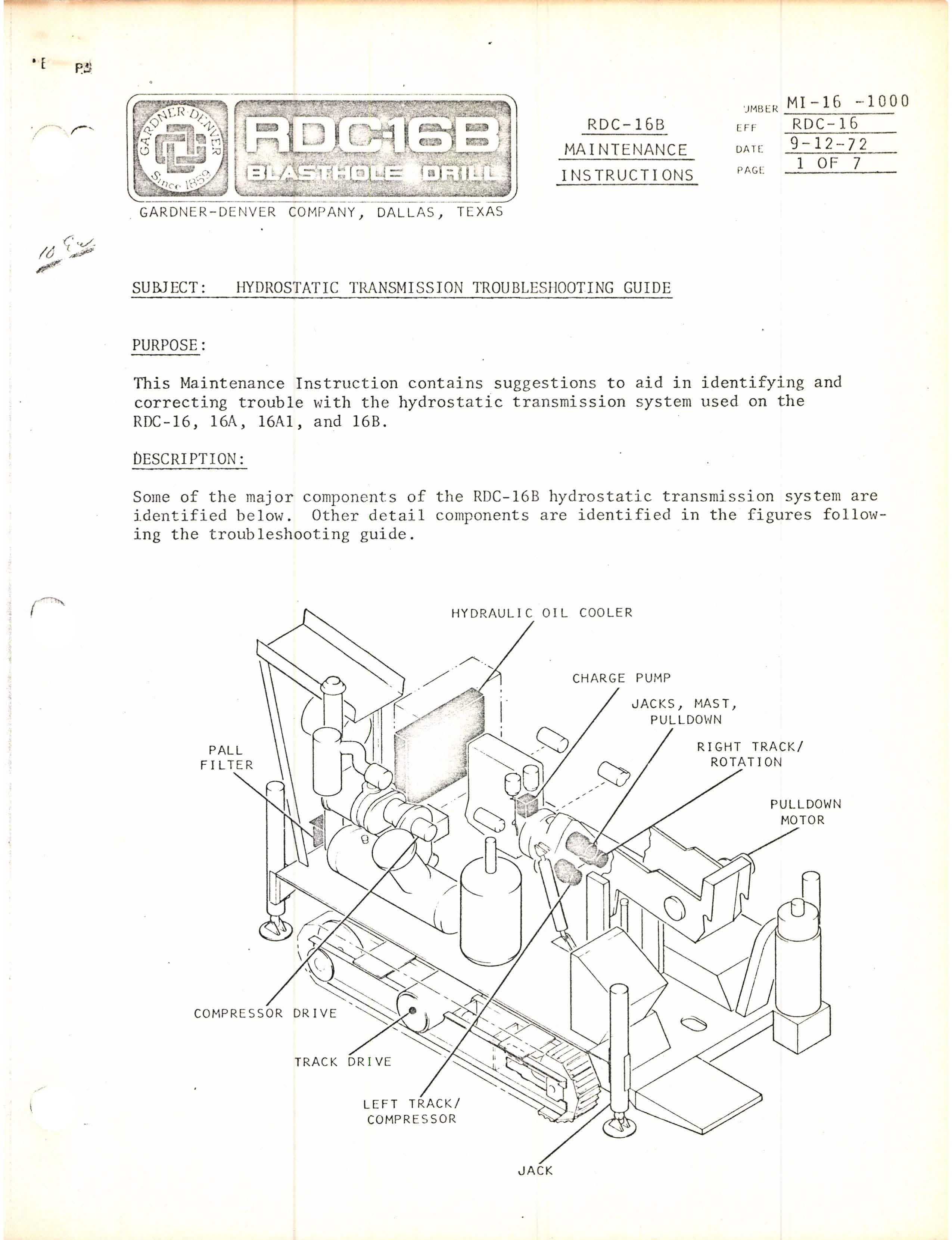
SUBJECT: HYDROSTATIC TRANSMISSION TROUBLE SHOOTING GUIDE
PURPOSE:
This Maintenance Instruction contains suggestions to aid in identifying and correcting trouble with the hydrostatic transmission system used on the RDC-16, 16A, 16Al, and 16B.
DESCRIPTION:
Some of the major compon e nts of the RDC-16B hydrostatic transmis s ion system are identified below. Other detail components are identified in the figures follm'Ving the troubleshooting guide.

Check case drain flow per No te 3. IJZ ::t>c mc:o rn ;:0 ..... 01 it (J"'\ --...; ...... o o o ;:0 o (") 1 ...... (J"'\ ::t> Z -; m Z ::t> z (") rn Z (f) -; ;:0 c (") -; o z (f)
Remedy
RDC-16B HYDROSTATIC TRANSMISSION Cause

Replace filter element.
Excessive Noise '>, ./
Do not attempt to clean element. Remove restriction.
Check for hose lin e r colla psing .
R e pla ce hos e, if necessary. Use recommended hydraulic fluid. Drain system, replace filter element, replace hydraulic fluid. Check suction line and fittings. Tighten fittings and repair leaks. Adjust high-pressure relief valve. (See Note 1.) Check case drain flow per Note 3.
If in excess of 3 gpm, replace pump or motor . Clean cooler to restore free air flow. (Check cooler daily and clean as needed .) Adjust high-pressure relief valve . (See N ote 1.)
If in excess of 3 gpm, replace pump or motor . BI009315
Low pressure filter dirty or plugged. b.
a.
Restriction in charge pump suction line . c.
Wrong hydraulic fluid. d.
Water in hydraulic fluid. e.
suction line or fittings, allo w ing air into the hydraulic fluid.
Loose
Worn pump or motor a llowi ng excessive case drain.
Bypassing through high-pressure relief valve. g.
Air flow through hydraulic oil cooler restricted.
Worn pump or motor allowing excessive case drain.
f.
a.
Overheating
2.
Bypassing through high-pressure re lief valve. c.
b.

BI009315
;;0 o n 1 ..... '" }> Z -i rn Z }> z n rn z U1 -i ;;0 C n -i o z U1 -oz }>C rnOJ rn ;;0 01" ...... -...J '" ..... o o o
Replace if necess ary . Check pilot and seat for nicks or irregular seating pattern. Check O-rings for cuts, abrasion, or high-pressure erosion. Clean if necessary. Replace if new part available. " 'j
If not, clean with 500 abrasive cloth until free in working bore. Replace. Install ball (see parts book). ..."
(Check daily and maintain proper l eve l. ) Adjust relief valve (see Note 1 ) . Adjust pUmp compensator (see Note 1). Check case drain flow per N ote 3 .
If in excess of 3 gpm, replace pump. Check charge pump output.
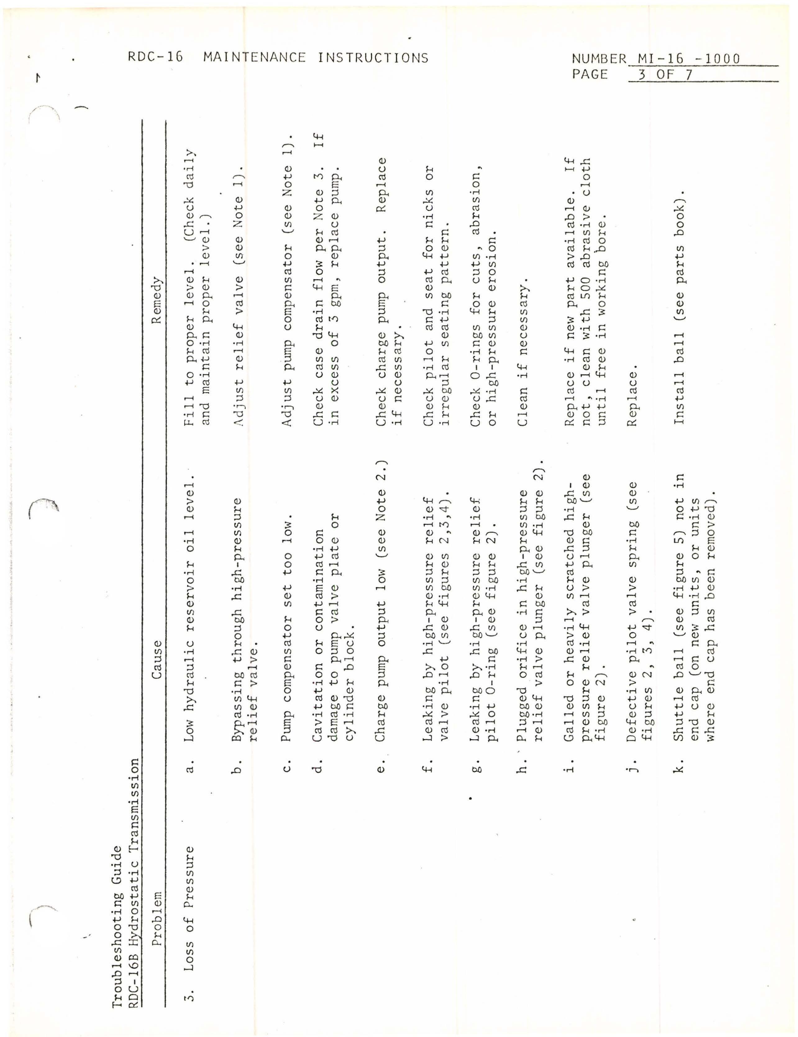
Troubleshooting Guide
Cause
Low hydraulic reservoir oil level. ·
Bypassing through high-pressure relief valve.
Pump compensator set too low.
Cavitation or contamination damage to pump valve plate or cylinder block.
Charge pump output low (see Note 2.)
Leaking by high-pressure relief valve pilot (see figures 2,3,4).
Leaking by hi g h-pressure relief pilot O-ring (see figure 2).
Hydrostatic Transmission Problem
RDC-16B
a.
b.
c.
d.
e.
f.
g.
h. ' Plugged orifice in hi g h-pressure relief valve plunger (see figure 2).
Galled or heavily scratched highpressure relief valve plunger (see fi gu re 2) .
i.
Defective pilot valve spring (see fi g ures 2, 3,4).
j.
Shuttle ball (see figure 5) not in end cap (on new units, or units where end cap has been remov ed) .
k.
Loss of Pressure
3.

Troubleshooting Guide
Remedy
Check mechanical linkage to pump control lever.
Repair or replace (see parts book).
Repair or replace (see parts book). Replace spring (see parts book). Replace spring (see parts book). Replace sleeve (see parts book). Replace assembly (see parts book).
Repla ce O-ring (see parts bOO K) .
Replace. BI009315
Replace drain line if defective. Worn seal. -oz »c 03:rnOJ rn /0 01"...... -.....J (J""\ o o o /0 o n 1 ...... (J""\ 3: » z -i rn Z » z n rn z (j) -i ;0 C n -i o Z tl)
Cause
No control either direction.
Broken pin or no pin on pump lever arm. (see figure 5).
Broken cam follower in pressure compensator control (see Figure 5).
Broken pressure ov erride spring (see figure 5).
Bro ken sleeve spring (see figure 5).

Sticking valve sleeve . (see figure 5). Valve sleeve assembly bent, not engaging pin (see figure 5).
Damaged or cut O-ring on piston (see figure 5).
liner.
Hydrostatic Transmission Problem
RDC-16B
a.
b.
c.
d.
e.
f. g.
h.
Lip extrudes outward.
a.
Lip does not extrude outward.
b.
Failure of Control Lin kage (Mecha nic a l)
5.
Shaft Seal Leakage
6.

To check relief valve setting:
Note 1.
Install 0-6000 psig hydraulic gage in ports indicated in figure 1, or tee located in front of hydraulic pumps.
a.
Lock tracks by pumping hydraulic hand pump.
Start engine.
b.
Place left pump control in forward tram p osition (selector valve should be in tram position ) .
c.
Loosen jam nut on pump compensator control (see fi g ure 5).
d.
Turn adjusting screw clock w ise,
pressure on g a ge.
Do not exc e ed 5500 psig.
Units with case drain flo w in excess of 3 gpm should be replaced. --= ;0 0 n 1 ..... en P z --l rn Z P z n rn Z (fl --l ;0 C n --l 0 Z (fl ""1JZ PC rn co rn ;0 01 ." ...... '.J en ...... Cl Cl Cl
Hi g hest pressure obtained will be relief v a lv e setting.
Return pump compensator setting to n a meplate setti n g on control.
e.
Normal unit should dr a in up to 1.5 gpm maximu m. -J IE BI009315
f.
If relief valve was not set per p u mp housing nameplate, add shims as shown in figures 2 and 3 (.001 per SO psig incr ea se desired ) . N ote 2.
specifies that charge pump pressure should be 25 psig per 1000 psig operating pressure.
A 4000 psig system should have a minimum 100 psig charge pump pressure to m aintain control of functions.
P ressure may be checked by installing ga g e to tee on hydraulic pump relief v a lve p a ck ag e (see figures 3 and 4).
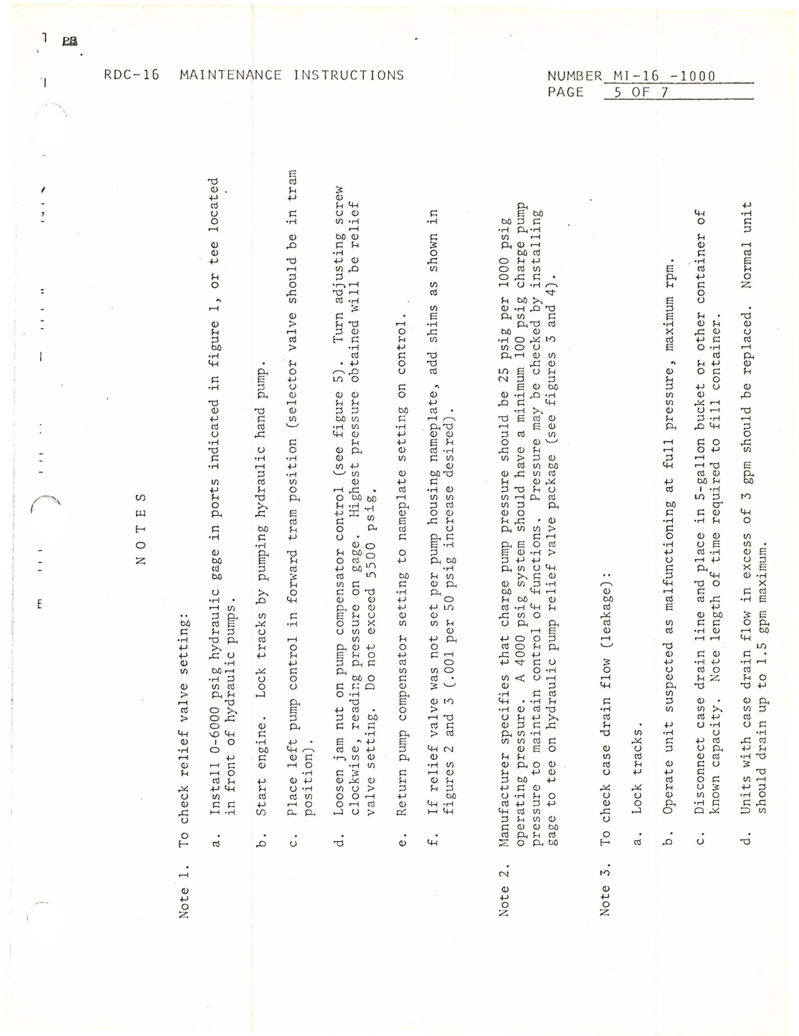
To check case drain flow (leakage):
Note 3.
Lock tracks.
Operate unit suspected as malfunctioning at full pressure, maximum rpm.
a.
b.
Disconnect case drain line and place in S-gallon bucket or other container of known capacity.
c.
N ote length of time required to fill container.

NUMBER MI-16 -1000
RDC - 16 , MAINTENANCE INSTRUCTIONS PAGE 6 OF 7

ARROW S INDICATE PORTS WHERE GAGE CAN BE INSTALLED
HIGH PRESSURE RELI EF VALVE
CHECK THESE O-RINGS
CHECK P I LOT & SEAT
• Thank you very much for reading the preview of the manual.
• You can download the complete manual from: www.heydownloads.com by clicking the link below
• Please note: If there is no response to CLICKING the link, please download this PDF first and then click on it.