BLOWTORCH MAINTENANCE INSTRUCTIONS
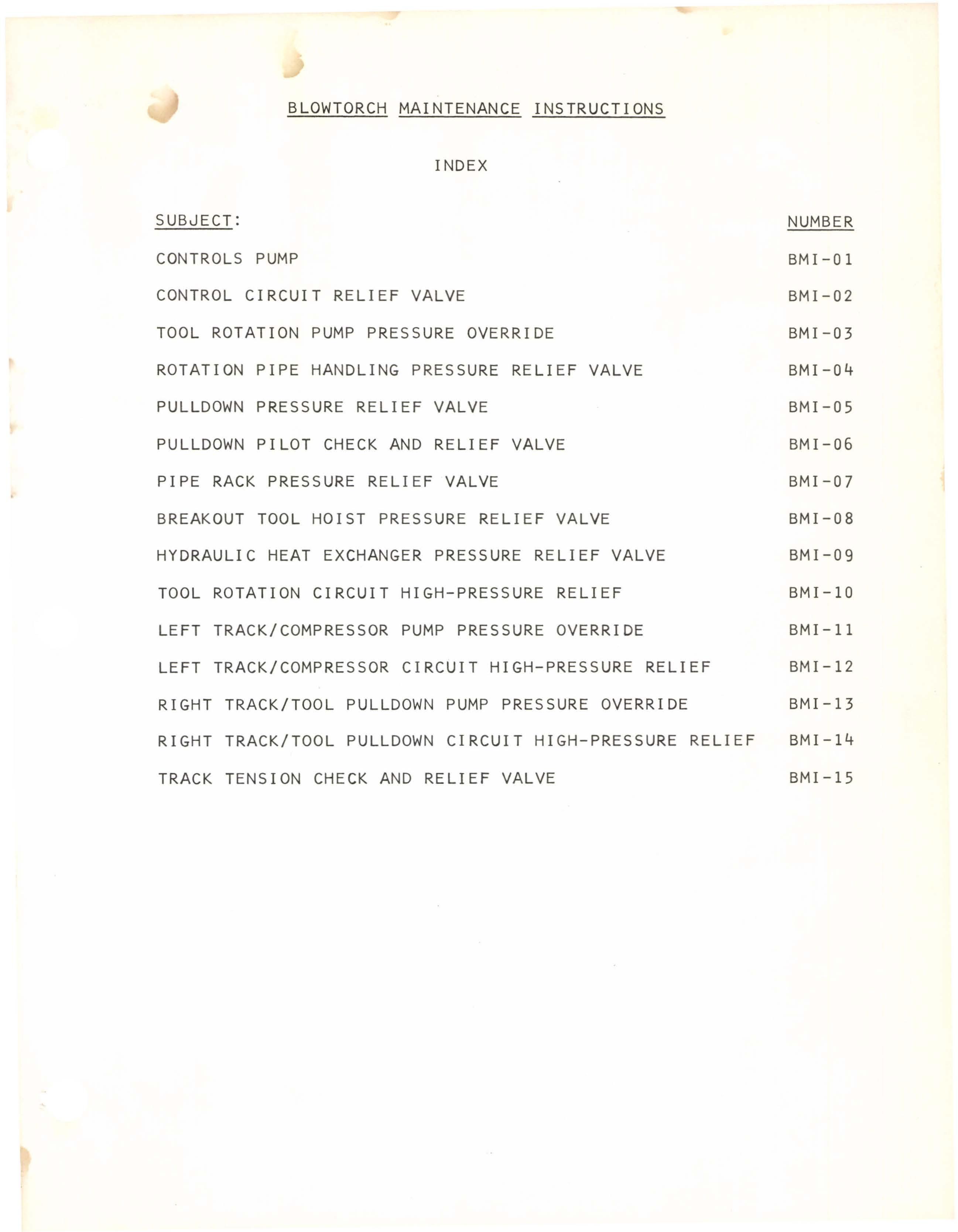
INDEX
SUBJECT:
CONTROLS PUMP
CONTROL CIRCUIT RELIEF VALVE
TOOL ROTATION PUMP PRESSURE OVERRIDE
ROTATION PIPE HANDLING PRESSURE RELIEF VALVE
PULLDOWN PRESSURE RELIEF VALVE
PULLDOWN PILOT CHECK AND RELIEF VALVE
PIPE RACK PRESSURE RELIEF VALVE
BREAKOUT TOOL HOIST PRESSURE RELIEF VALVE
HYDRAULIC HEAT EXCHANGER PRESSURE RELIEF VALVE
TOOL ROTATION CIRCUIT HIGH-PRESSURE RELIEF
LEFT TRACK/COMPRESSOR PUMP PRESSURE OVERRIDE
LEFT TRACK/COMPRESSOR CIRCUIT HIGH-PRESSURE RELIEF
RIGHT TRACK/TOOL PULLDOWN PUMP PRESSURE OVERRIDE
RIGHT TRACK/TOOL PULLDOWN CIRCUIT HIGH-PRESSURE RELIEF
TRACK TENSION CHECK AND RELIEF VALVE
NUMBER BMI-Ol BMI-02 BMI-03 BMI-04 BMI-05 BMI-06 BMI-07 BMI-08 BMI-09 BMI-IO BMI -11 BMI-12 BMI-13 BMI-14 BMI-15 BI009636

BI009636
BLASTHOLE DRILL
NUMBER BMI - 01
EF F
DA TE --,7,-_1_3_-_7_1..."....-_
PAGE 1 OF 2
THIS BULLETIN IS THE PROPERTY OF GARDNER-DENVER COMPANY AND IS RESTRICTED FROM RELEASE TO UNAUTHORIZED PERSONS. INSTRUCTIONS ARE SUBJECT TO CHANGE WITHOUT PRIOR NOTICE.
SUBJECT: CONTROLS PUMP--PRESSURE AND FLOW ADJUSTMENT

DESCRIPTION: Delavan Pressure Compensator Variable Displacement Pump. Pressure compensator control is adjustable. When the control is set, pump automatically compensates to deliver fluid necessary to reach and maintain set pressure.
FUNCTION: Supplies hydraulic flow to mast positioning cylinders, pipe rack, breakout tool, angle drill pipe support, track tension, track brake release, and tool lower cavity.
LOCATION: Top right position on pump drive gearbox.
ADJUST PRESSURE AT TOP SCREW
ADJUST FLOW VOLUME AT BOTTOM SCREW
CONTROL PUMP
Model IMPm BLDWTDRCH
BLOWTORCH MAINTENANCE
INSTRUCTIONS
BI009636

BI009636
PRESSURE ADJUSTMENT
Setting - 2000 psi.
Special Tools - none.
Adjustment Procedure
1. With rig engine not running, remove protective cap (top cap on motor). Be sure locknut does not back off with cap.
2. Start rig engine and set speed at idle (around 550 to 600 rpm).
3. Loosen adjustment screw locknut. (Hold adjustment screw to keep it from turning with locknut).
4. Adjust to set pressure at 2000 psi. Read pressure on CONTROL PUMP gage.
NOTE: If 2000 psi cannot be obtained, check control circuit pressure relief valve setting. (See BMI - 02.)
5. Hold adjustment screw and tighten locknut.
6. Replace and secure protective cap. Be sure locknut does not turn.
FLOW ADJUSTMENT
Flow volume control is factory set, and should never require re-adjustment. The only reason for needing adjustment would be unauthorized tampering to limit or restrict the flow. Such restriction would be indicated by unusually sluggish operation of the functions listed above, and excessive CONTROL PUMP pressure drop during their operation.

If restriction is suspected, check or reset as follows: Setting - Maximum flow.
Special Tools - none.
Adjustment Procedure
Rig parked and braked. Engine off.
No system pressure (check CONTROL PUMP gage).
1. Remove protective cap (lower cap on motor).
2. Loosen adjustment screw locknut.
3. Adjust to 1-5/16 inches from the top face of the adjustment port plug to the top of the adjustment screw.
ADJUSTMENT SCREW
4. Hold adjustment screw and tighten locknut.
5. Reinstall protective cap. Be sure locknut does not turn.
NUMBER BMI - 01 PAGE 2 OF 2
BLOWTORCH MAINTENANCE INSTRUCTIONS
BI009636

BI009636
BLDWTDRCH
NUMBER BMI - 02 IMP - III
EFF
DA TE _7::---_1_4_-_7_1-..---_
PAGE 1 OF 2
THIS BULLETIN IS THE PROPERTY OF GARDNER-DENVER COMPANY AND IS RESTRICTED FROM RELEASE TO UNAUTHORIZED PERSONS. INSTRUCTIONS ARE SUBJECT TO CHANGE WITHOUT PRIOR NOTICE.
SUBJECT: CONTROL CIRCUIT RELIEF VALVE PRESSURE ADJUSTMENT

DESCRIPTION: Pressure relief valve with sliding spool type relief mechanism.
FUNCTION: Receives hydraulic flow from controls pump. Through internal porting, distributes to control functions. Relieves at set pressure to prevent system over-pressure in event of control pump malfunction. Relief fluid returned to hydraulic reservoir.
LOCATION: Hydraulic console next to hydraulic filter.
PRESSURE RELIEF VALVE
Model IMPm
BLASTHOLE DRILL BLOWTORCH MAINTENANCE INSTRUCTIONS
BI009636

BI009636
BLOWTORCH MAINTENANCE INSTRUCTIONS

PRESSURE ADJUSTMENT
Setting - 2500 psi.
Special Tools - none.
Adjustment Procedure
1. With rig engine not running, remove protective cap from control circuit relief valve AND FROM CONTROL PUMP PRESSURE COMPENSATOR ADJUSTMENT. (See BMI - 01).
2. Start rig engine and set at idle speed (around 550 to 600 rpm). CONTROL PUMP gage should register 2000 psi.
3. Loosen adjustment screw locknuts on both valve and pump.
4. Turn relief valve adjustment screw in to increase relief pressure above 2500 psi.
5. Adjust control pump pressure to slightly over 2500 psi. Read pressure on CONTROL PUMP gage.
6. Back off relief valve adjustment screw until pressure relieves to 2500 psi.
7. Hold relief valve adjustment screw and tighten locknut.
8. Replace and secure relief valve protective cap. Be sure locknut does not turn.
9. Adjust control pump pressure to 2000 psi.
10. Hold adjustment screw and tighten locknut.
11. Replace and secure protective cap. Be sure locknut does not turn.
12. Kill engine or proceed with other operations.
NUMBER PAGE BMI - 02 2 OF 2
BI009636
• Thank you very much for reading the preview of the manual.
• You can download the complete manual from: www.heydownloads.com by clicking the link below
• Please note: If there is no response to CLICKING the link, please download this PDF first and then click on it.

CLICK HERE TO DOWNLOAD THE COMPLETE MANUAL
CLICK HERE TO DOWNLOAD THE COMPLETE MANUAL