Technical Manual
• Thank you very much for reading the preview of the manual.
• You can download the complete manual from: www.heydownloads.com by clicking the link below
• Please note: If there is no response to CLICKING the link, please download this PDF first and then click on it.


Marion 8200 Walking Dragline
MAINTENANCE AND OPERATION
- Table of Contents -
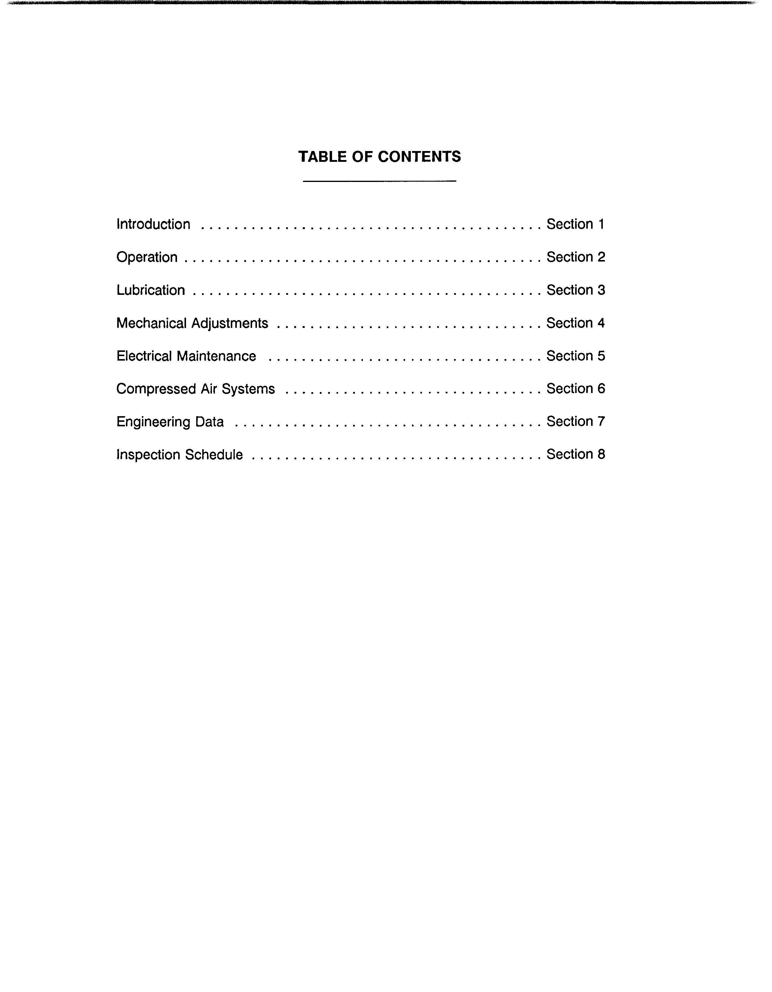
This manual is divided into major sections covering the various servicable components and systems of the 8200 Walking Dragline. These sections and their contents are organized as shown below.
Section 1 INTRODUCTION
Section 2 OPERATION
Section 3 LUBRICATION
Section 4 MECHANICAL ADJUSTMENTS

Section 5 ELECTRICAL MAINTENANCE
Section 6 COMPRESSED AIR SYSTEMS
Section 7 -- ENGINEERING DATA
Section 8 -- INSPECTION SCHEDULE
IMPORTANT NOTE l ! The information and documentation enclosed were developed and assembled by the Marion Division of ! llNDRESCO Inc. for the limited purpose of relating necessary technological material to our customers. !
1The contents herein were developed end produced at substantial expense and are valued by Marion!
1Division at a proprietary level. Therefore, this information and documentation is being furnished solely!
! for use with the subject machine and is not to be used, reproduced or disclosed in any way, in whole! ! or in part, without the prior express written permission of Merion Division of INDRESCO Inc.

TABLE OF CONTENTS


ADANGER:
THIS MANUAL IS INTENDED TO PROVIDE INFORMATION AND DATA FOR MAINTENANCE AND OPERATION ON THIS MACHINE. THE ELECTRICAL EQUIPMENT INVOLVED SHOULD BE SERVICED/ONLY BY QUALIFIED INDIVIDUALS WHO HAVE BEEN PROPERLY TRAINED TO WORK WITH HIGH VOLTAGE SYSTEMS AND WARD-LEONARD LOOP DC DRIVES. FAILURE TO COMPLYWOULDRESULT IN PERSONAL INJURY OR DEATH.

ADANGER:
DO NOT ATTEMPT ANY MAINTENANCE, MECHANICAL OR ELECTRICAL, ON THIS MACHINE WITHOUT FULL UNDERSTANDING OF THE COMPONENT OPERATION AND INTERNAL PARTS. COMPONENTS UTILIZING ELECTRICAL POWER, AIR PRESSURE, HYDRAULIC PRESSURE AND COMPRESSION OR TENSION SPRINGS FOR OPERATION MUST BE DEACTIVATED AND ISOLATED PRIORTO DISASSEMBLY.
The FEEDER CABLE must contain a provision for a ground connection, especially where 2300 volts and above are used. The power line end must attach (see the paragraph on ground circuits) to a suitable permanent ground. The machine end must securely attach through a bolted connection to ground the machine frame. This provides a constant ground for the machine and electrical equipment. Failure to provide this adequate ground endangers employees and equipment.
POWER LINE GROUNDING CIRCUIT ADEQUATE FOR THE MACHINE CANNOT BE OVER-EMPHASIZED. Without a good grounding system, high voltage exists between the machine and the ground. The portable cable and power lines supplying the machine must have a ground wire, ample in capacity, running parallel to the main wires over the entire distance from the transformer to the machine. A suitable grounding system must be used at the transformer. Consult the local electric supplier for details.
ADANGER:
DUET01NHERENT DANGERS IN THE OPERATION OF ANY HIGH VOLTAGE ELECTRICAL EOUIPMENT, A SAFE GROUNDING SYSTEM SHOULD INCLUDE GROUND CONDUCTORS IN THE CABLE, A NEUTRAL GROUNDING RESISTOR, AND RELATED RELAYS AND SWITCHGEAR. A GROUND CONTINUITY CHECK SYSTEM IS ALSO RECOMMENDED.


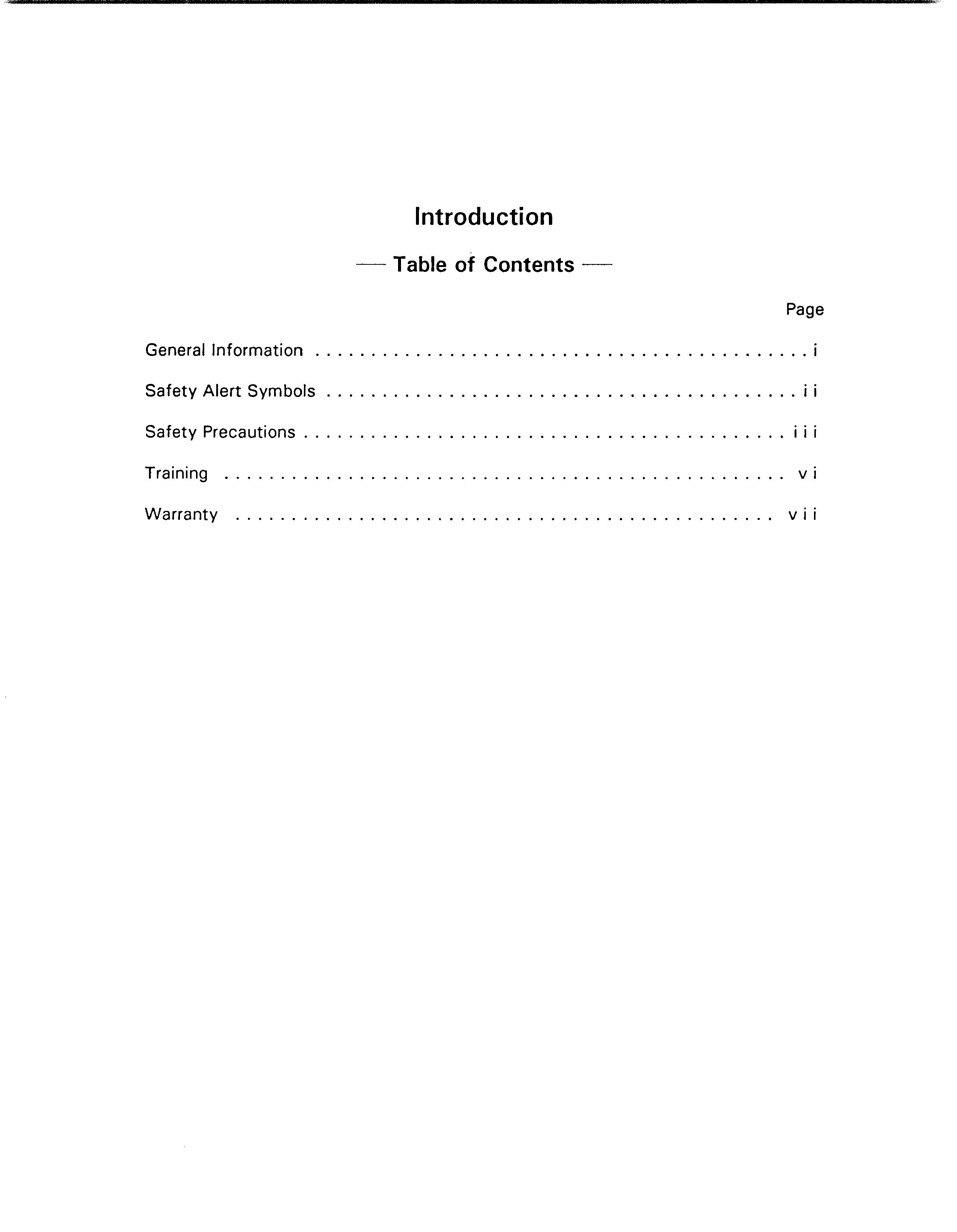
Introduction
GENERAL INFORMATION
This manual is designed to assist the owner in the operation and preventive maintenance of this machine. Following easy to understand step-by-step procedures, maintenance personnel can perform these tasks in a safe manner. When a systematic and thorough maintenance/service procedure (a responsibility of the maintenance superintendent) is used for this machine, minimum unplanned downtime and reliable operation will result.

THIS MANUAL IS NOT THE PARTS BOOK, and cannot be used to order parts. A separate, detailed parts book has been supplied. Please carefully read the instructions in it. All parts are listed by group and/or product code numbers with item/part numbers for THIS SPECIFIC MACHINE. Order parts in exact quantity. Parts ordered by mistake and returned, are subject to a rehandling charge. R/GHT HAND and LEFT HAND parts on the upper frame correspond to the operator's hands at the controls; as seated when operating the machine. Please state the correct machine SERIAL NUMBER (located on a plate in the operator's cab) when corresponding or contacting factory service or parts departments. Records on each machine are filed by serial number and when given this number, your machine's specific design and original equipment is accessed quickly by the Marion parts representative.
Periodic additions or revisions may be made to this manual. These will be mailed direct to you from the factory. Should you require additional information or factory service assistance contact your regional service representative or
Service Department
Marion Division of INDRESCO Inc.
617 West Center Street
P.O.Box 505 Marion, OH 43302
or Telephone 61 4/383-5211
Telex 24-5307
Telecopier 614/383-5211
It is Marion's policy to improve its products whenever possible and practical to do so. The company reserves the right to make changes or add improvements at any time without incurring any obligation to install such changes on machines sold previously.
Due to this continuous program of product research and development some procedures, specifications and parts may be altered in a constant effort to improve machines.
• Thank you very much for reading the preview of the manual.
• You can download the complete manual from: www.heydownloads.com by clicking the link below
• Please note: If there is no response to CLICKING the link, please download this PDF first and then click on it.

