
Technical Manual
• Thank you very much for reading the preview of the manual.
• You can download the complete manual from: www.heydownloads.com by clicking the link below
• Please note: If there is no response to CLICKING the link, please download this PDF first and then click on it.

TABLE OF CONTENTS
General Information
Air System and Components
Lubrication
Engineering Data
Mechanical Adjustments
Electrical Maintenance
Welding Instruction
Centralized Lubrication System
Installation of Open & Semi-Enclosed Gear Set
Instruction for Shrink Fit Pinions Wire Rope Care Strand Handling

SECTION I
GENERAL INFORMATION
INTRODUCTION
This manual is provided for the guidance of all persons who operate, lubricate, adjust or maintain the Marion 8050 Walking Dragline. The information was prepared with the purpose in mind of furnishing accurately and concisely all the data necessary to the operation and servicing of this machine.
All information, measurements, and specifications herein are in accord with the Marion Power Shovel Engineering Department and should be strictly adhered to in all work on this machine.
PARTS BOOK
TillS MANUAL IS NOT A PARTS BOOK AND SHOULD NOT BE USED IN ORDERING PARTS.
You have been furnished detailed Parts Books which list all parts by group numbers with items and part numbers for your specific machine.
Read carefully the instructions in the front of the Parts Book for ordering parts.
SERIAL NUMBER OF MACHINE
Be sure that the serial number of the machine is given in any letters, telegrams, orders or other communications. Records for each individual machine are filed by serial number and if this number is available, the design and original equipment can be quickly and accurately checked.
RIGHT AND LEFT HAND PARTS
On the upper frame, right hand (R. H. ) and left hand (L. H. ) correspond to the operator's right and left hands when he is facing the bucket while at the operator 1 s controls.
The company reserves the right to improve or change the design of its products and specifications thereof and the company shall incur no liability thereby or any obligations to install such improvements on products previously sold.
SAFETY PRECAUTIONS
The usefulness of this machine depends entirely on the man at the controls. The operator is its brains. He must think safety and work safely.
Neatness and safety go hand in hand. Good housekeeping habits should be developed.
1. Keep the floor clean and free from oil and grease.
2. Keep the walkways clean, clear, and free from obstructions.
3. Prevent the accumulation of grease and oil around bearings and gears. Grease and oil collect and hold grit and dirt which work into finely machined parts.
4. A clean machine is easier to operate - easier to inspect - easier to service.
5. Keep hands and clothing away from moving parts.

6. Replace guards, inspection plates, access covers, etc., promptly after reason for removal is accomplished.
Strip mining equipment is subject to tremendous stresses and shock loads. These stresses are thoroughly studied and considered in the design and building of Marion equipment.
This machine is built with an ample reserve of power and strength and is well fitted to meet the demands of its task.
However, the Marion engineers cannot foresee the conditions imposed by abuse, mismanagement and neglect. These factors are more damaging to any piece of equipment than years of continuous operation and normal wear.
Aside from regular lubrication, proper and accurate adjustments, the personnel should be aware of any deviation from the normal, which could be evidence of impending breakdown or components failure.

The maintenance people should inspect, during their rounds, all structural members for evidence of stressed, broken or loose parts. Evidence of a member stretching, bending, or deflecting can often be determined by the conditions of the surface paint. Stressed parts will show wrinkles or waves in the paint or check marks.
Breaks or chips in the surface or a collection of dust along a line may indicate a crack in the metal. Pay particular attention to those areas around openings where corners or angles are cut out, at the ends of gussets or at brace connections and at transitional points where heavy and thin parts join.
Stress in a monolithic structure may travel some distance from the damaged area and manifest itself at a remote point in some seemingly unrelated place.
The maintenance people should check all bolts, nuts, cap screws and rod bolts. Lock washers and other locking devices must be in place.
Be sure that bolted and assembled parts are tight. Evidence of movement may be detected by signs of scuffed paint, worn or bright spots adjacent to the part. Often a slight movement of parts that can't be seen with the eye can be felt with the finger tip when the machine is working.
Grease or oil stains that are unaccountable, or out of place are often evidence of a fault.
If any part or parts shows wear or distortion beyond that expected from normal wear, replacement part should be made available at once and promptly installed. The cost of prompt replacement of parts is negligible compared to the cost of breakdown - loss of production and man hours.


SECTION 2
AIR SYSTEM AND COMPONENTS

INTRODUCTION
The hoist, drag, propel and swing brakes of the 8050 walking dragline are released by compressed air. Compressed air is also used to actuate the automatic lubrication system.
The Marion air control system is simple in operation and, with reasonable care and maintenance, will have a long trouble free life.
The system can best be explained by a brief description of its components and their functions in the system. Fig. 1 shows a schematic view of the complete system used on the machine.
The operator must be constantly aware of the air pressure gauge reading. If at any time the pressure drops below the operating differential, 90 psi to 120 psi, the operator should shut down the machine and investigate the cause.
Do not operate the machine without full tank pressure.
AIR COMPRESSOR
The air compressor that supplies the system is located on the rotating frame at the right of the center journal.
The compressor is a complete unit that includes a storage tank, electric motor and a two stage air compressor with a pressure switch. Read· the manual that is attached to the unit.
Check the oil level in the compressor crank case daily. Keep the oil level to the full mark on the dip stick. Drain and flush the crank case every 500 hours of operation. Refill with oil specified on the chart "Oil Specifications" in the lubrication section.
The air cleaner located at the air compressor intake is an oil bath type cleaner. The cleaner should be disassembled
and cleaned once a week under normal conditions. In dusty and dirty conditions clean daily. Fill with oil to the mark on the side of the cup with the same grade of oil as used in the crank case.
AIR VALVES
The air valves are electrically controlled, pilot operated non-compensating valves. Valves are normally closed.
The valve can be disassembled from the machine without removing the piping. Valves are attached by two socket head cap screws. Use flat screw driver in the notch to lift the body from the base.
AIR VALVES
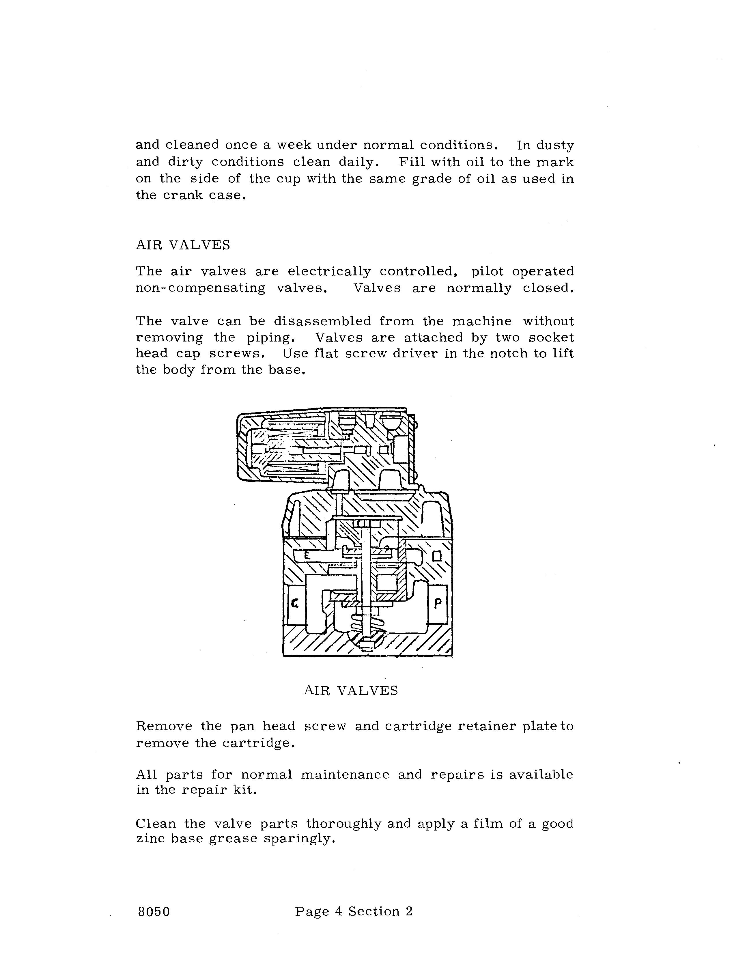
Remove the pan head screw and cartridge retainer plate to remove the cartridge.
All parts for normal maintenance and repair s is available in the repair kit.
Clean the valve parts thoroughly and apply a film of a good zinc base grease sparingly.
Magnet valves are rugged and require little or no attention.
If the valve fails to shut off or to admit the proper volume of air, the valve should be cleaned as dirt and scale can cause the valve to leak.
Open and close the valve several times by means of the hand lever on top of the valve. The valve can usually be cleaned this way without disassembling the valve.
If not, dismantle the valve and clean or replace the worn or damaged parts.
The anti-freezer is a pressurized unit that is installed in the system to prevent icing and freeze-up when operating at temperatures below or near freezing.
The unit is installed in the delivery line from the compressor far enough away so that the heat will not effect the unit. The anti-freezer introduces an alcohol vapor into the air stream that mixes with the water vapor in the air.
 Wick_-tt- II
Chamber Chamber
ANTI - FREEZER
ANTI - FREEZER
Wick_-tt- II
Chamber Chamber
ANTI - FREEZER
ANTI - FREEZER
The unit shown consists of an alcohol chamber at the bottom and a vapor chamber at the top. A hex plug in the top is fitted with a central rod. The rod is covered with a tubular wick that carries alcohol up into the vapor chamber. This unit is non-adjustable.
Before filling, release the pressure in the line and vent the unit by loosening the plug at the top of the unit. Remove the filler plug and fill with approximately one (1) quart of methyl (wood) alcohol. NOTE: Do not use ethyl alcohol or radiator anti -freeze (ethylene glycol). In certain areas the use of alcohol in air systems is forbidden. Use "Kill Frost" or "Freeze Ban".
• Thank you very much for reading the preview of the manual.
• You can download the complete manual from: www.heydownloads.com by clicking the link below
• Please note: If there is no response to CLICKING the link, please download this PDF first and then click on it.