• Thank you very much for reading the preview of the manual.
• You can download the complete manual from: www.heydownloads.com by clicking the link below
• Please note: If there is no response to CLICKING the link, please download this PDF first and then click on it.

INTRODUCTION
This manual covers the operation, preventive maintenance, and troubleshooting of the 55-R Rotary Blast Hole Drill. '
Every effort has been made to make this manual as complete as possible at the time of printing. However, Bucyrus-Erie Company reserves the right to improve its products continually. For this reason product changes may be made that are not included in this manual.
This manual is divided into eight chapters. Each chapter is divided into sections. Pages are numbered within each chapter and section. For example, page 2-2-1 is the first page of Section 2 within Chapter 2. Each chapter has a Table of Contents located at the beginning of the chapter.
NOTE
Warnings, Cautions and Notes serve as critical reminders to alert mining crews of unusual situations and forewarn them of possible hazards on the excavation site. Heed these warnings at all times:
WARNINGS indicate potential machine damage that may result from failure to comply with the particular instructions therein.
CAUTIONS indicate that personal injury, death, or machine damage may result from failure to comply with the instructions.
NOTES stress a point or give additional information concerning the procedure being discussed.
CONTENTS
CHAPTER
GENERAL DESCRIPTION OF THE MACHINE, MAJOR MACHINE SYSTEMS, AND COMPONENTS.
CHAPTER
OPERATING INFORMATION INCLUDING SAFETY, PRE-START CHECKS; OPERATING CONTROLS, START-UP AND OPERATING HINTS.
CHAPTER
MAINTENANCE AND REPAIR OF MECHANICAL COMPONENTS
CHAPTER 4
DUST CONTROL MAINTENANCE AND COMPONENT REPAIR
CHAPTER
AIR SYSTEM MAINTENANCE AND COMPONENT REPAIR
CHAPTER
HYDRAULIC SYSTEM MAINTENANCE AND COMPONENT REPAIR
CHAPTER
LUBRICATION
CHAPTER 8
ELECTRICAL MAINTENANCE AND ADJUSTMENTS
THRU 8-5-14
GENERAL
DESCRIPTION
The 55-R drill is a rotary blast hole drill. It is designed to drill blast holes in quarries and strip mines. The standard machine will drill 50 feet in a single pass (60 feet optional).
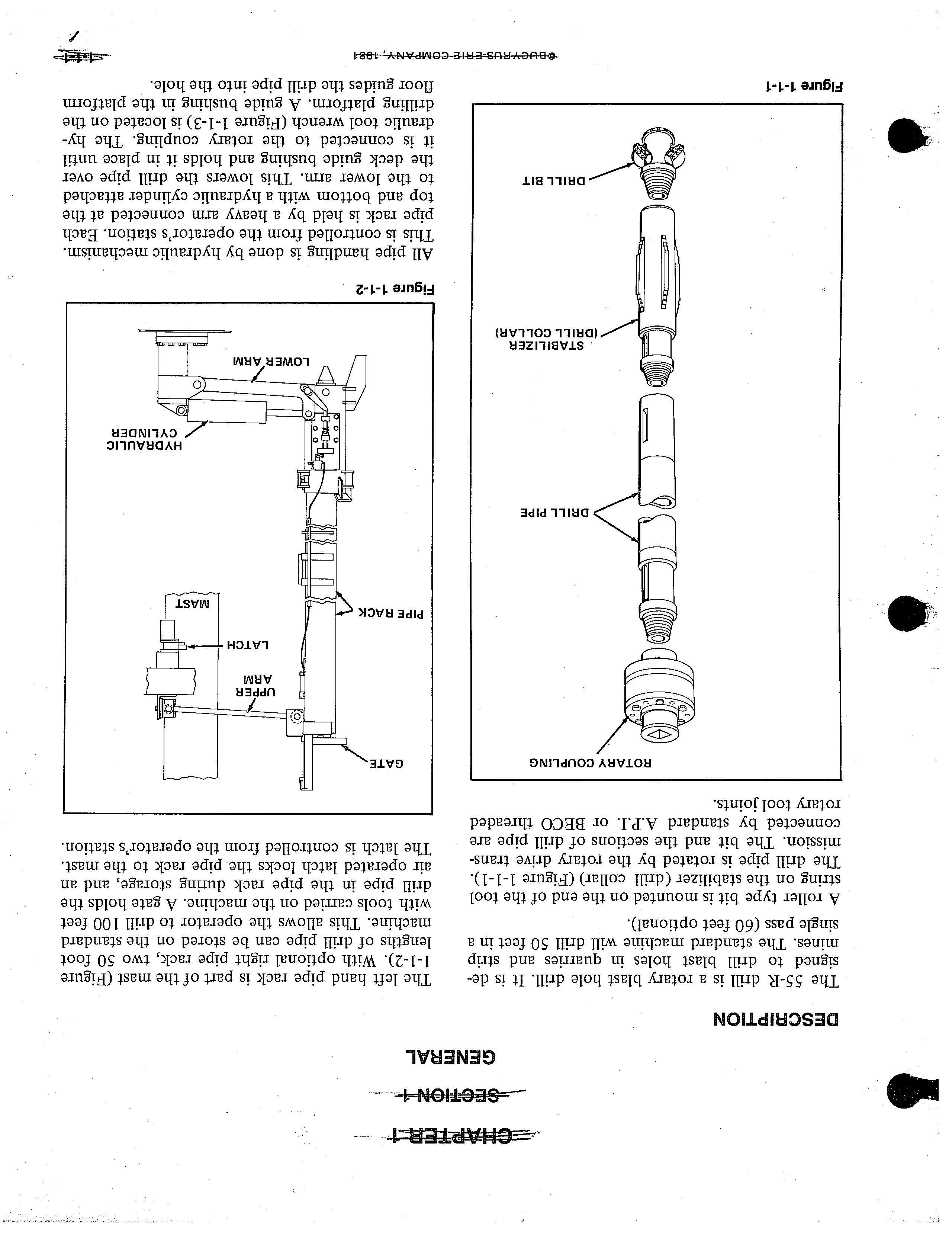
A roller type bit is mounted on the end of the tool string on the stabilizer (drill collar) (Figure 1-1-1). The drill pipe is rotated by the rotary drive transmission. The bit and the sections of drill pipe are connected by standard A.P.I. or BECO threaded rotary tool joints.
The left hand pipe rack is part of the mast (Figure 1-1-2). With optional right pipe rack, two 50 foot lengths of drill pipe can be stored on the standard machine. This allows the operator to drill 100 feet with tools carried on the machine. A gate holds the drill pipe in the pipe rack during storage, and an air operated latch locks the pipe rack to the mast. The latch is controlled from the operator's station.
All pipe handling is done by hydraulic mechanism. This is controlled from the operator's station. Each pipe rack is held by a heavy arm connected at the top and bottom with a hydraulic cylinder attached to the lower arm. This lowers the drill pipe over the deck guide bushing and holds it in place until it is connected to the rotary coupling. The hydraulic tool wrench (Figure 1-1-3) is located on the drilling platform. A guide bushing in the platform floor guides the drill pipe into the hole.
The rotary drive transmission (Figure 1-1-4) is driven by an AC "Wound Rotor" motor. It is mounted on the mast. The operator can vary the speed of rotation while drilling. This allows him to select the most efficient speed for any rock formation.
A rotary vane air compressor or optional screw type air compressor supplies compressed air to the bit (Figure 1-1-6). The air cools and cleans the bit bearings and removes the drill cuttings from the hole. A dust enclosure confines cuttings around the hole. Some machines are equipped with the optional AMERpulse dust control. This is an automatic self-cleaning fabric tube type dust collector. Water injection dust control is also available as an option.
The rotary drive unit is raised and lowered by a chain drive. A gear case mounted to the lower front of the mast (Figure 1-1-5) drives the rotary unit pull down chain. There are three clutches on the gear case, one operates the pulldown, one the hoist and the third the auxiliary winch. The sp_rockets in the gear case are driven by a hydraulic motor.
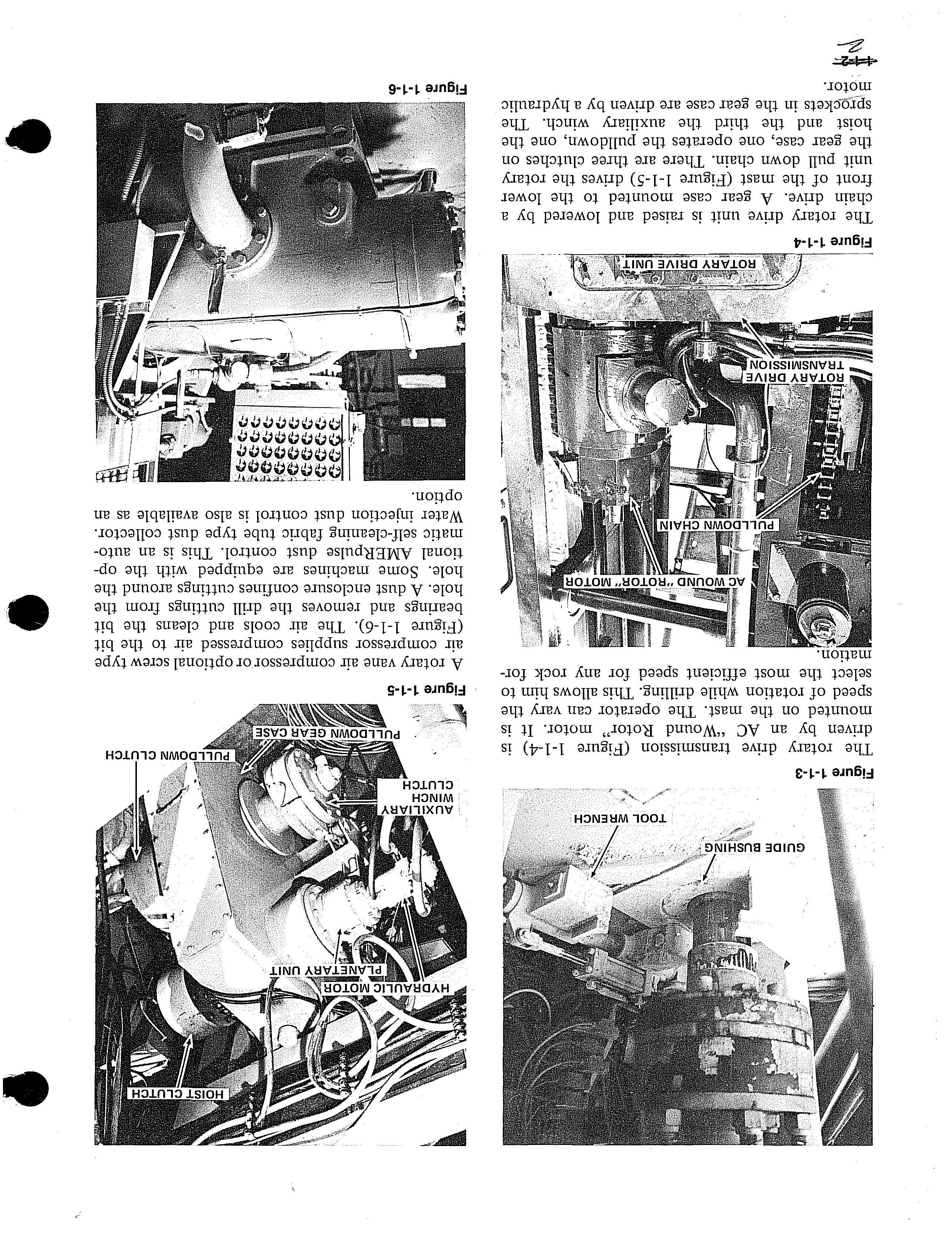 Figure 1-1-3
Figure 1-1-4
Figure 1-1-3
Figure 1-1-4
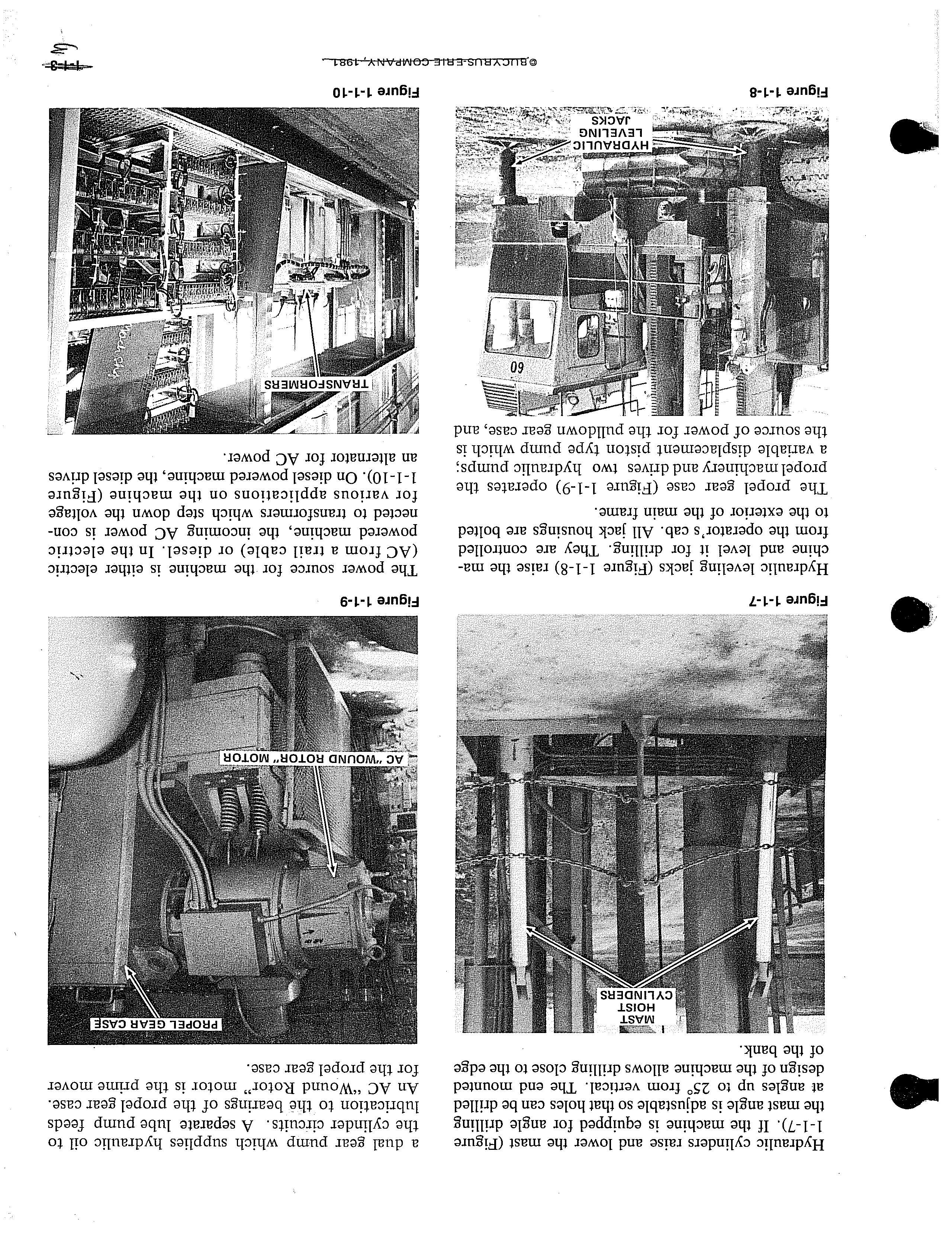
Hydraulic cylinders raise and lower the mast (Figure 1-1-7). If the machine is equipped for angle drilling the mast angle is adjustable so that holes can be drilled at angles up to 25° from vertical. The end mounted design of the machine allows drilling close to the edge of the bank.
a dual gear pump which supplies hydraulic oil to the cylinder circuits. A separate lube pump feeds lubrication to the bearings of the propel gear case . An AC "Wound Rotor" motor is the prime mover for the propel gear case.
Hydraulic leveling jacks (Figure 1-1-8) raise the machine and level it for drilling. They are controlled from the operator's cab. All jack housings are bolted to the exterior of the main frame.
The propel gear case (Figure 1-1-9) operates the propel machinery and drives two hydraulic pumps; a variable displacement piston type pump which is the source of power for the pulldown gear case, and
The power source for the machine is either electric (AC from a trail cable) or diesel. In the electric powered machine, the incoming AC power is connected to transformers which step down the voltage for various applications on the machine (Figure 1-1-10). On diesel powered machine, the diesel drives an alternator for AC power.
The machinery house and the operator's cab are completely enclosed and pressurized with filtered air. The operator can control all functions of drilling without leaving the control console (Figure 1-1-11). All operating controls are grouped accordingly to function, within easy reach. The operator has a view of the drilling platform, pipe, and mast.
FRONT AND REAR
The front of the machine is the power unit end. The rear of the machine is the operator's end. Left and right are determined from the operator's seat, facing the control panel. The operator's cab is located on the right side at the rear of the machine.
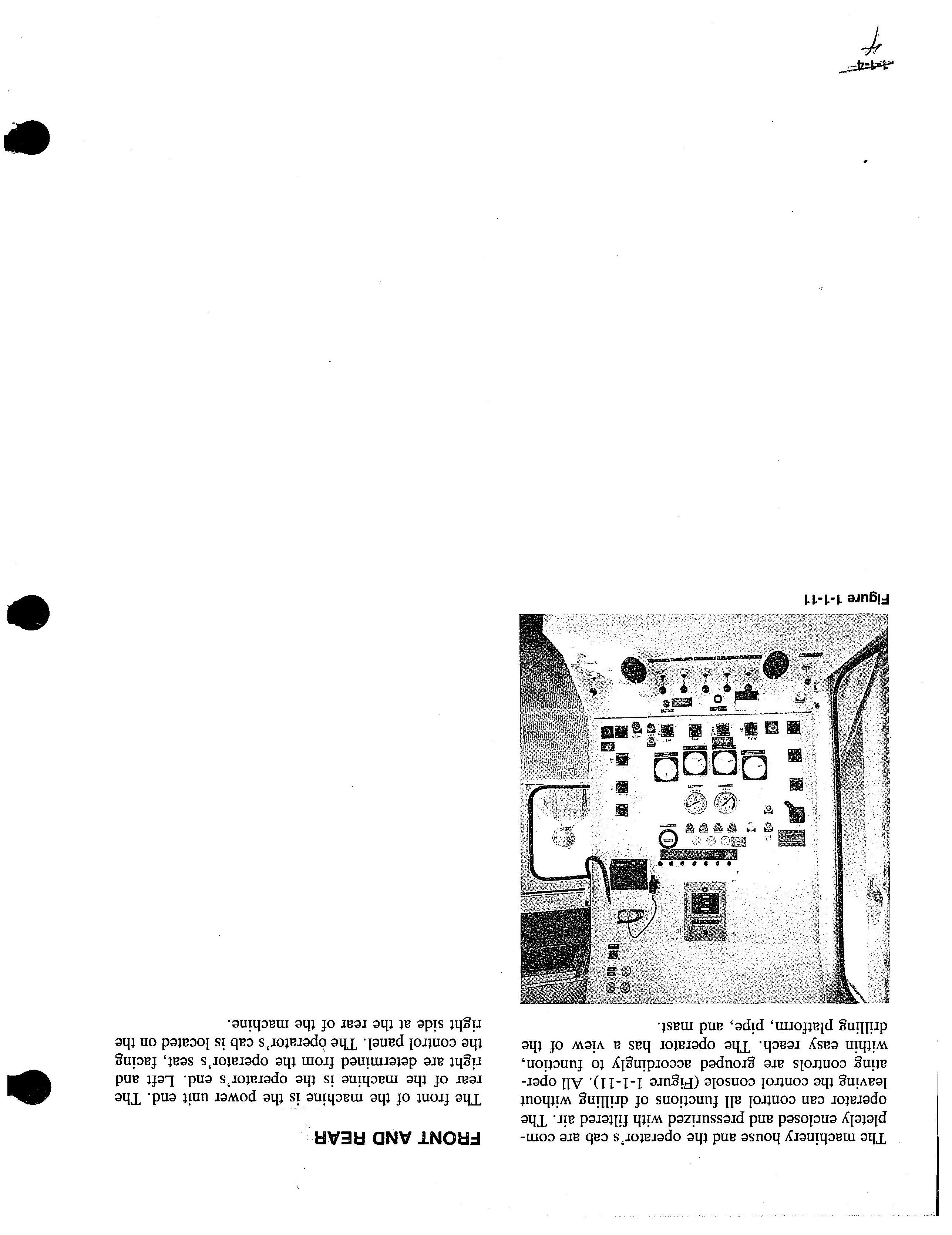 Figure 1-1-11
MACHINE COMPONENTS - MECHANICAL LOWER WORKS
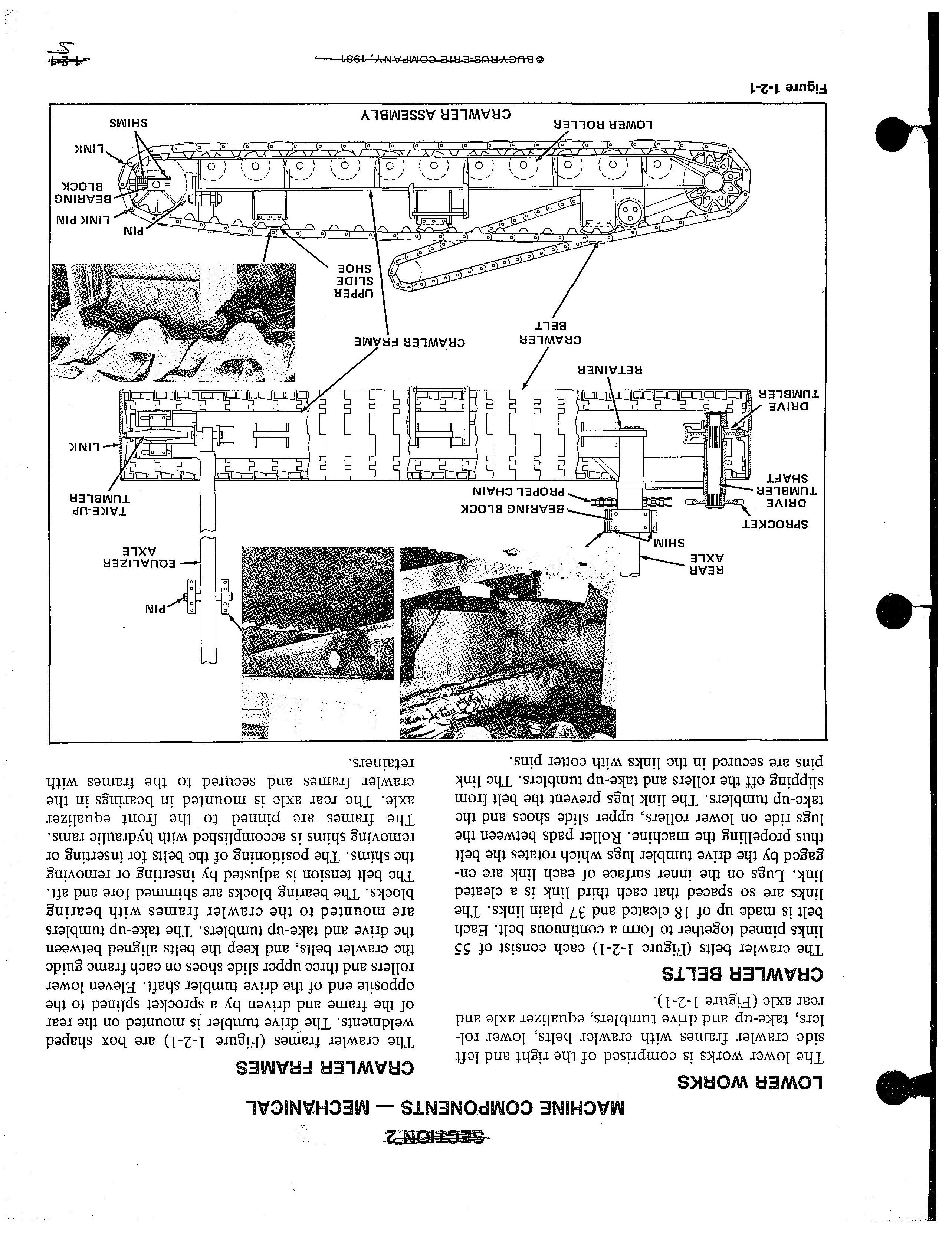
The lower works is comprised of the right and left side crawler frames with crawler belts, lower rollers, take-up and drive tumblers, equalizer axle and rear axle (Figure 1-2-1).
CRAWLER BELTS
The crawler belts (Figure 1-2-1) each consist of 55 links pinned together to form a continuous belt. Each belt is made up of 18 cleated and 37 plain links. The links are so spaced that each third link is a cleated link. Lugs on the inner surface of each link are engaged by the drive tumbler lugs which rotates the belt thus propelling the machine. Roller pads between the lugs ride on lower rollers, upper slide shoes and the take-up tumblers. The link lugs prevent the belt from slipping off the rollers and take-up tumblers. The link pins are secured in the links with cotter pins.
CRAWLER FRAMES
The crawler frames (Figure 1-2-1) are box shaped weldments. The -drive tumbler is mounted on the rear of the frame and driven by a sprocket splined to the opposite end of the drive tumbler shaft. Eleven lower rollers and three upper slide shoes on each frame guide the crawler belts, and keep the belts aligned between the drive and take-up tumblers. The take-up tumblers are mounted to the crawler frames with bearing blocks. The bearing blocks are shimmed fore and aft. The belt tension is adjusted by inserting or removing the shims. The positioning of the belts for inserting or removing shims is accomplished with hydraulic rams. The frames are pinned to the front equalizer axle. The rear axle is mounted in bearings in the crawler frames and to the frames with retainers.
LEVELING JACK
OPERATOR'S CAB
ELECTRICAL CABINETS
MACHINERY HOUSE AUXILIARY AIR COMPRESSOR
LEVELING JACK-
UPPER WORKS
DRILLING PLATFORM AND DUST ENCLOSURE
LEVELING·JACK
WATER INJECTION TANK OR AMER-PULSE
RESISTOR GRIDS
CYLINDER HYDRAULIC CIRCUIT RESERVOIR
-LEVELING JACK
EQUALIZER AXLE
The equalizer axle (Figure 1-2-1) is a welded beam which pins to the crawler frames directly behind the take-up tumbler, and to the main frame. The center pin is held to the main frame by bearing blocks. This arrangement allows the main frame to remain level while propelling on unlevel ground.
REAR AXLE
The rear axle (Figure 1-2-1) is mounted to the crawler frames ahead of the drive tumbler and secured with retainer plates and capscrews. The axle is mounted to the main frame with bearing blocks. The bearing blocks are shimmed fore and aft. The final drive propel chain is adjusted by inserting or removing the shims. The positioning of the near axle for removing or inserting shims is accomplished with hydraulic rams.
UPPER WORKS
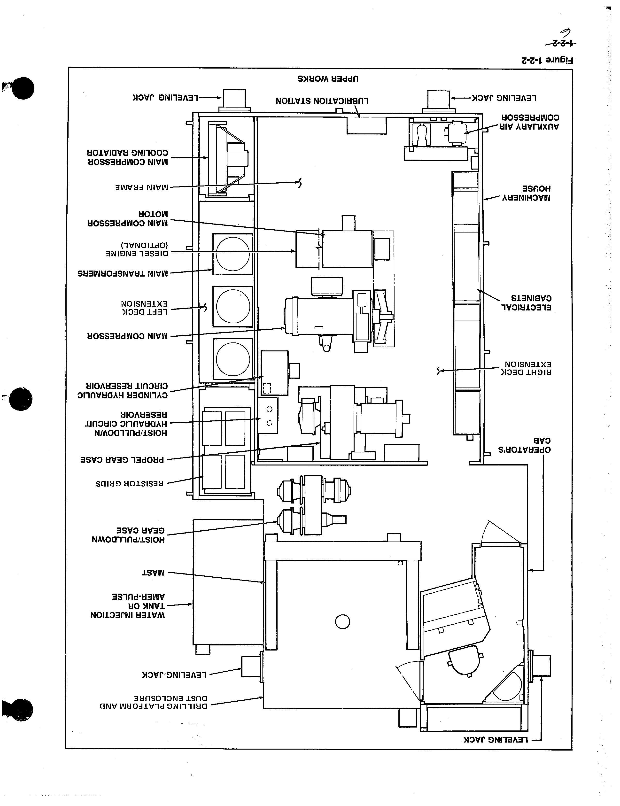
The upper works (Figure 1-2-2) consists of the main frame, the right and left deck extensions, the operator's cab, the machinery house, the leveling jacks and the dust enclosure. Within the operator's cab and the machinery house are all the controls and machinery for operating the drill.
MAIN FRAME AND DECK EXTENSIONS
The main frame is an all welded frame (Figure 1-2-2). It provides support for the machinery and equipment. All beams and load carrying frame members are alloy steel. The right deck extension bolts to the main frame and supports the electrical cabinets and auxiliary air compressor. On the latest machines the right deck extension also includes the operator's cab. The left deck extension bolts to the main frame and supports the main air compressor radiator, the AC resistor grids and, on all electric drills, transformers. On diesel machines the diesel radiator occupies the area the transformers use on electric drills.
LEVELING JACKS
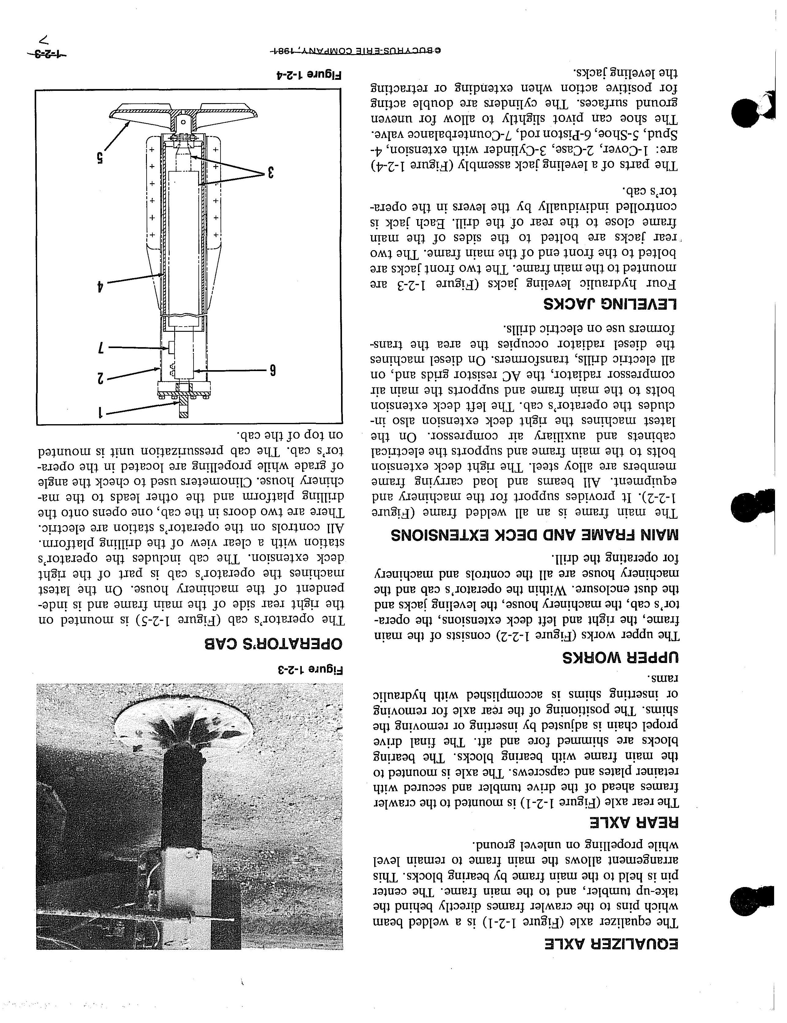
Four hydraulic leveling jacks (Figure 1-2-3 are mounted to the main frame. The two front jacks are bolted to the front end of the main frame. The two ·rear jacks are bolted to the sides of the main frame close to the rear of the drill. Each jack is controlled individually by the levers in the operator's cab.
The parts of a leveling jack assembly (Figure 1-2-4) are: 1-Cover, 2-Case, 3-Cylinder with extension, 4Spud, 5-Shoe, 6-Piston rod, ?-Counterbalance valve. The shoe can pivot slightly to allow for uneven ground surfaces. The cylinders are double acting for positive action when extending or retracting the leveling jacks.
OPERATOR'S CAB
The operator's cab (Figure 1-2-5) is mounted on the right rear side of the main frame and is independent of the machinery house. On the latest machines the operator's cab is part of the right deck extension. The cab includes the operator's station with a clear view of the drilling platform. All controls on the operator's station are electric. There are two doors in the cab, one opens onto the drilling platform and the other leads to the machinery house. Clinometers used to check the angle of grade while propelling are located in the operator's cab. The cab pressurization unit is mounted on top of the cab.
MACHINERY HOUSE
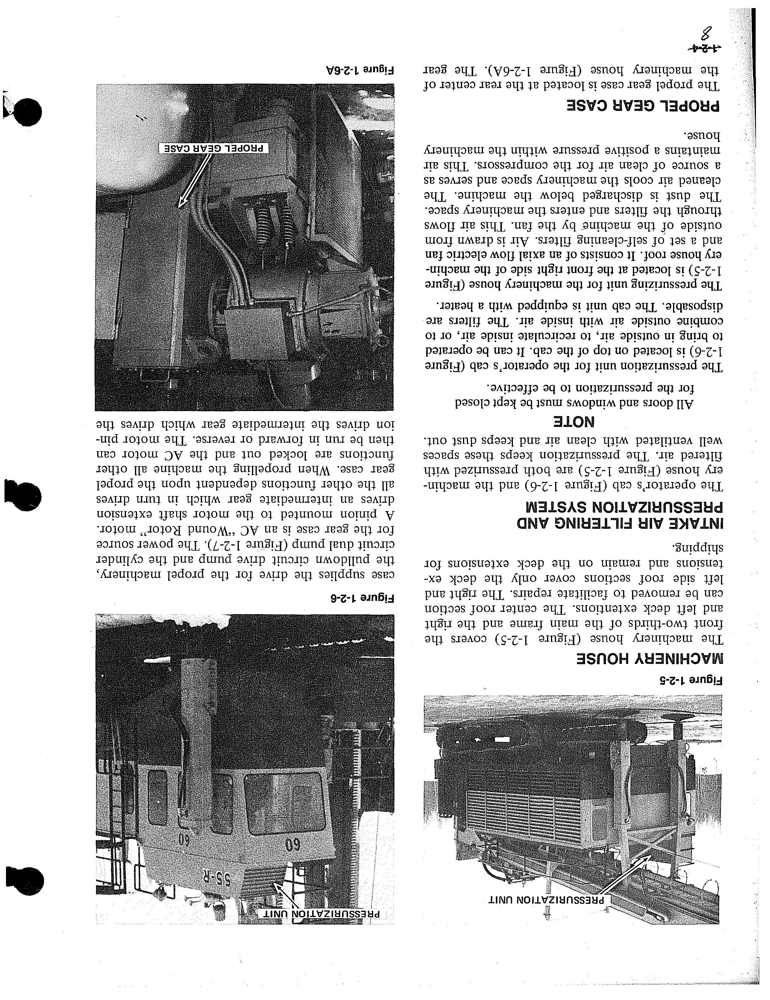
The machinery house (Figure 1-2-5) covers the front two-thirds of the main frame and the right and left deck extentions. The center roof section can be removed to facilitate repairs. The right and left side roof sections cover only the deck extensions and remain on the deck extensions for shipping.
INTAKE AIR FILTERING AND PRESSURIZATION SYSTEM
The operator's cab (Figure 1-2-6) and the machinery house (Figure 1-2-5) are both pressurized with filtered air. The pressurization keeps these spaces well ventilated with clean air and keeps dust out.
NOTE
All doors and windows must be kept closed for the pressurization to be effective.
The pressurization unit for the operator's cab (Figure 1-2-6) is located on top of the cab. It can be operated to bring in outside air, to recirculate inside air, or to combine outside air with inside air. The filters are disposable. The cab unit is equipped with a heater.
The pressurizing unit for the machinery house (Figure 1-2-5) is located at the front right side of the machinery house roof. It consists of an axial flow electric fan and a set of self-cleaning filters. Air is drawn from outside of the machine by the fan. This air flows through the filters and enters the machinery space. The dust is discharged below the machine. The cleaned air cools the machinery space and serves as a source of clean air for the compressors. This air maintains a positive pressure within the machinery house.
PROPEL GEAR CASE
The propel gear case is located at the rear center of the machinery house (Figure l-2-6A). The gear
...:1-2-4-
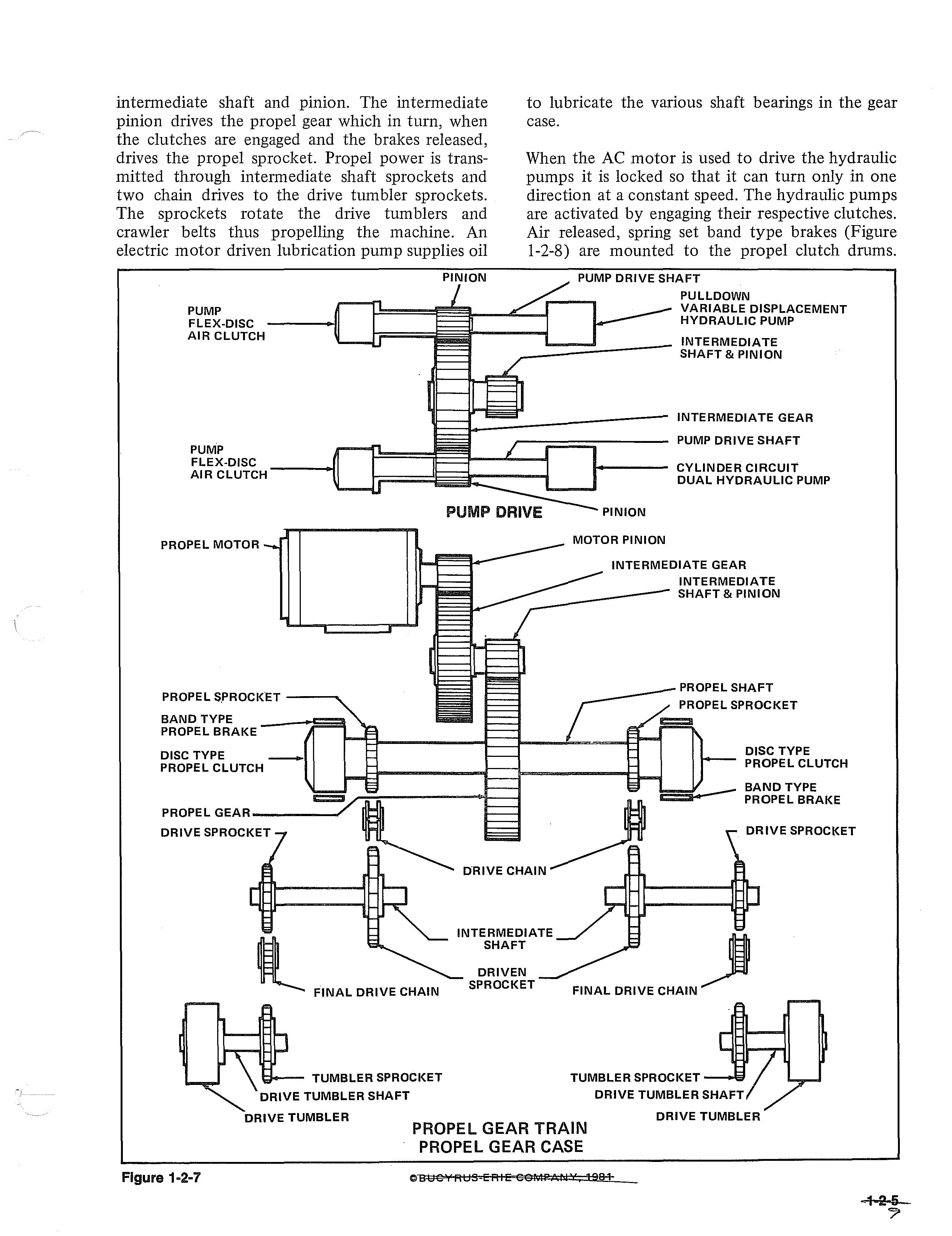
case supplies the drive for the propel machinery, the pulldown circuit drive pump and the cylinder circuit dual pump (Figure 1-2-7). The power source for the gear case is an AC "Wound Rotor" motor. A pinion mounted to the motor shaft extension drives an intermediate gear which in turn drives all the other functions dependent upon the propel gear case. When propelling the machine all other functions are locked out and the AC motor can then be run in forward or reverse. The motor pinion drives the intermediate gear which drives the
Figure 1-2-5intermediate shaft and pmwn. The intermediate pinion drives the propel gear which in turn, when the clutches are engaged and the brakes released, drives the propel sprocket. Propel power is transmitted through intennediate shaft sprockets and two chain drives to the drive tumbler sprockets. The sprockets rotate the drive tumblers and crawler belts thus propelling the machine. An electric motor driven lubrication pump supplies oil
PUMP FLEX-DISC AIR CLUTCH
to lubricate the various shaft bearings in the gear case.
When the AC motor is used to drive the hydraulic pumps it is locked so that it can turn only in one direction at a constant speed. The hydraulic pumps are activated by engaging their respective clutches. Air released, spring set band type brakes (Figure 1-2-8) are mounted to the propel clutch dmms.
PULLDOWN VARIABLE DISPLACEMENT HYDRAULIC PUMP
INTERMEDIATE SHAFT & PINION
INTERMEDIATE GEAR PUMP DRIVE SHAFT
PUMP FLEX-DISC AIR CLUTCH
PROPEL MOTOR
PROPEL S.PROCKET -----...
BAND TYPE PROPEL BRAKE
DISC TYPE PROPEL CLUTCH
PROPEL GEAR---------' DRIVE SPROCKET
DRIVE
1---- CYLINDER CIRCUIT DUAL HYDRAULIC PUMP
INTERMEDIATE GEAR
INTERMEDIATE SHAFT & PINION
PROPEL SHAFT
DISC TYPE PROPEL CLUTCH
BAND TYPE PROPEL BRAKE
DRIVE SPROCKET
DRIVE TUMBLER
DRIVE TUMBLER
PROPEL GEAR TRAIN
PROPEL GEAR CASE
fl" 1984-
• Thank you very much for reading the preview of the manual.
• You can download the complete manual from: www.heydownloads.com by clicking the link below
• Please note: If there is no response to CLICKING the link, please download this PDF first and then click on it.